Design
The fiber-reinforced bending actuator documented here consists of a core bladder reinforced with a strain-limiting layer and inextensible fibers. This section of the documentation describes some of the design considerations involved in making your own actuator, followed by a detailed tutorial on designing the required molds. Solid model files of the actuator and molds can be downloaded here (SolidWorks 2013) and .stl files of the molds can be downloaded here.
Since design decisions are closely tied to the fabrication process, here we provide a brief overview of the steps involved (a more detailed explanation is available in the Fabrication section).
|
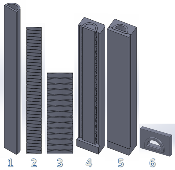
1. The actuator core is a hollow semi-cylindrical tube molded out of elastomer. 2. The inextensible, strain-limiting layer is a sheet of fiberglass attached to the flat face of the actuator core, preventing that face from lengthening when inflated. 3. The entire actuator is wrapped with inextensible Kevlar thread, which restricts radial expansion. 4. This thread wrapping is secured in place by molding an additional outer "skin" layer which encapsulates the threads and the actuator core. 5. Finally, the actuator is plugged at both ends, forming a closed chamber. A vented screw is installed in one of the end caps to provide access for an air source to inflate the chamber. |
|
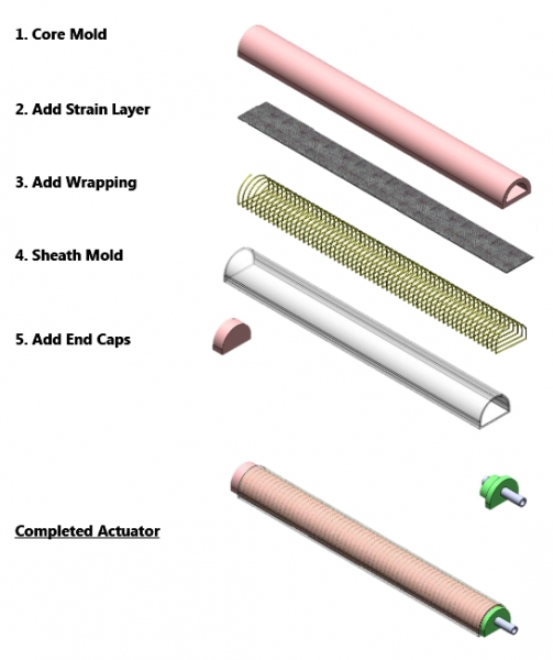
This fabrication approach involves a multi-step molding process. The actuator core is cast on a steel half-round which serves multiple purposes: providing the hollow central chamber, aligning the actuator within the molds, and providing structural reinforcement during the attachment of the strain limiting layers.

| SRT_FR Mold SolidWorks Files.zip | 17.95 MB | |
| SRT_FR Mold STL Files.zip | 2.01 MB |
Variation: Motion
By varying the configurations of the strain-limiting components of the actuator (the inextensible layer and fiber wrapping), different motions can be achieved when the actuator is inflated. Here, we discuss how to achieve three types of motion: bending, twisting, and extension. These motion types can be combined, for example it is possible to design an actuator that will bend and twist when inflated. Furthermore, it is possible to vary the strain-limiting configuration along the length of a single actuator so that different behaviors can be achieved at different locations. See the case study for an example application of this approach.
Bending
 |
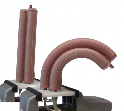
By wrapping the fiber reinforcement in a symmetrical, double-helix configuration, the actuator is prevented from expanding radially and can only expand axially. The addition of a strain-limiting sheet of inextensible material prevents this expansion on one side of the actuator, resulting in an overall bending motion.
Extending
 |
Again, a symmetrical, double-helical fiber wrapping limits radial expansion. However, in this configuration we do not add an inextensible layer and as a result the actuator will expand in the axial direction when inflated.
Twisting
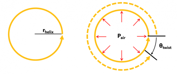
By using a single helical wrapping instead of a symmetrical double helical wrapping like in the above 2 cases, a twisting motion can be achieved. As the elastomer core expands, the thread helix also increases in diameter. But since the thread is inelastic and fixed in length, the diameter increase must be compensated by a reduction in the number of coils – resulting in a twisting motion opposite to the direction of thread wrapping.
Twisting and Bending
Single-helical fiber wrapping combined with a strain-limiting layer results in twisting and bending.
 |
Twisting and Extending
Single-helical fiber wrapping with no strain-limiting layer results in bending and axial expansion.
 |
Combining multiple behaviors
The actuator can be divided into segments, with each segment having a different motion type. This enables the design of more complex and customized actuator behaviors. In the example shown, when the actuator is inflated the left-hand segment will bend, the central segment will extend in the axial direction, and the right-hand segment will twist and bend. The ability to "pre-program" complex behaviors like this is one of the primary advantages of soft robotics over traditional rigid robotics.


Variation: Morphology
Cross-section type
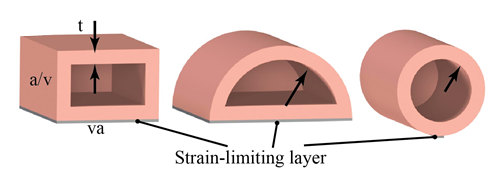
Three common cross-sectional shapes seen in soft actuators are rectangular, circular, and semi-circular. Assuming identical wall thicknesses and cross-sectional areas, we have found the following:
- The circular actuator is capable of applying the most bending torque for a given pressure, but it also has a high resistance to bending, making it the least efficient of the three shapes.
- The rectangular and semi-circular shapes have roughly similar efficiency. However, the rectangular cross-section deforms into a quasi-circular shape when pressurized, while the other two cross-section types maintain their original shapes.
- The sharp corners of the rectangular actuator may also increase the potential for stress concentrations and resulting fatigue/failure.
Radius, wall thickness, length
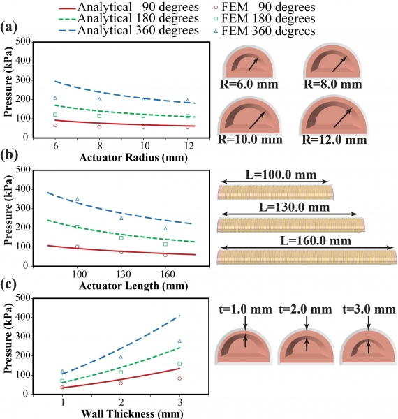 |
a) Increasing the radius of the actuator's semi-circular cross-section decreases the pressures required for the actuator to achieve a given amount of bending (in degrees). In addition, actuators with a larger radius (all other parameters being equal) achieve higher tip forces at a given pressure. b) Longer actuators require lower pressures to achieve the same amount of bending as their shorter counterparts. However, length did not greatly affect the force exerted at the actuator tip for a given pressure. c) Increasing wall thickness increases the pressures required for the actuator to achieve a certain amount of bending |
Fiber wrapping spacing
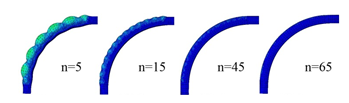
As the spacing of the fiber wrapping gets closer together (increasing turn number n), lower pressures are needed to achieve the same amount of bending. At low turn numbers with fibers spaced far apart, significant bulging and radial expansion is observed in the area between threads.
Variation: Material
Elastomer options
As discussed in the PneuNets bending actuator documentation, materials stiffness defines the amount of pressure required to actuate and the output forces attainable. Low durometer (high strain) materials will bend at lower pressures but will produce lower output forces.
We have found Elastosil M4601 silicone from Wacker Chemie AG or Dragon Skin 30 from Smooth-On Inc. to be useful for the core bladder of the actuator. Lower-durometer materials could be substituted to change the behavior of the actuator.
For the outer skin layer, which is applied to hold the reinforcements in place, we use a lower durometer material such as Ecoflex 20 or Dragon Skin 20. Using a higher-durometer material for the outer skin would make the actuator stiffer and require higher pressures to actuate.
Radial constraint options
| During the development of these actuators, various methods of adding radial constraints have been tried. For example, metal pinch rings can be used, but this leads to bulging in the actuators. | 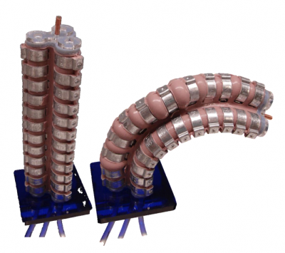 |
| Thread wrapping, though more labor intensive, allows for the most customization. It is possible to use different thread materials, but Kevlar is preferred for its strength. |
|
Inextensible layer options
In this documentation set we use fiberglass fabric as the strain-limiting layer. However, this can get messy, and in cases where the fiberglass is molded concurrently with the main chamber, stray fibers can create leaks. Any thin, inelastic material should work, including office paper or Tyvek. However, as these materials are less porous than fiberglass, they do not embed into silicone very well. To solve this, you can cut holes/slits into the material so that the elastomer can reach both sides.
Mold Design CAD Tutorial
This tutorial contains step-by-step instructions for making a solid model of a fiber-reinforced bending actuator mold in SolidWorks 2013. The SolidWorks part files can be downloaded here. If you prefer to use a different software package, you should be able to apply the general tutorial steps to most solid modeling environments.
Dimensions
The inner diameter of the actuator is defined by the steel rod used in the casting process. This tutorial and the associated part files assume that a 1/2" (12.7mm) diameter half-round rod will be used in the fabrication process.
The thickness of the actuator walls is defined by the difference between the rod diameter and the mold diameter. Here, we will create molds that will result in an actuator inner bladder with 2mm wall thickness.
Finally, the overall length of the actuator described here will be 170mm (6.7").
Of course, you can adjust these dimensions to suit your own design by modifying the relevant steps in the tutorial, or by editing the provided solid model files.
Overview
We will follow these steps to make our mold for the inner core of the actuator:
- Make the actuator body, an extruded semicircular tube (with filleted edges)
- Make one set of thread grooves with a swept cut. The sweep profile is a small circle, and the path is a helix.
- Mirror the swept cut to get the 2nd set of thread grooves.
- Make the main mold: create a base mold block, use an assembly to position the block relative to the actuator, then use the Cavity feature to subtract the actuator from the mold block.
- Repeat for the thin mold top, this time subtracting both the actuator and the main mold.
- Make the mold cap.
After making these molds, we can make the molds for the outer skin using the exact same process, even re-using the same solid model files:
- Make a copy of all the files in a new folder by opening the interim assembly for the top mold (which contains all the parts) and using File > Pack and Go. You should use the "Add Prefix" option to differentiate the new files. Do not just copy & paste files in Finder/Windows Explorer, as this will mess up your references!
- In the newly copied folder, open the actuator file. Get rid of the thread grooves by deleting the Mirror and Swept Cut features (check the "Also delete absorbed features" option to clean up the associated sketches).
- Increase the wall thickness by however thick you want the outer skin to be (1mm recommended). Just change the smart dimensions accordingly and rebuild the part.
- Open the interim assembly for the top mold, rebuild, and save. The main and top mold pieces will update themselves to fit the new actuator.
- If you feel that the top mold piece is too thin after the change, you can thicken the pieces. In the interim assembly, double click on the top mold. The smart dimensions will appear; double click the dimension corresponding to thickness and increase it. Next, double click on the bottom ledge of the main mold, and again modify the smart dimension so that the ledge width is increased by the same amount. Rebuild the assembly and save all the parts.
- The mold cap needs to be updated manually, but it is very easy: open the mold cap file, change the wall thickness smart dimensions in the sketch, and rebuild.
| SRT_FR Mold SolidWorks Files.zip | 17.95 MB |
Make actuator body
Note: Your document units should be in the MMGS system! If they aren't, change your settings by going to Options, selecting the Document Properties tab, and clicking on Units in the side menu.
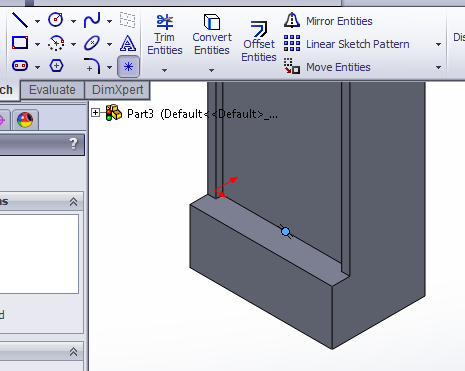
Draw base shape
 |
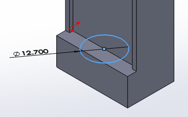
In the top plane, draw a 12.7mm diameter circle, centered at the origin. |
 |
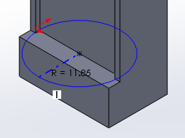
Draw a line across the diameter of the circle. |
|
|
Use the Trim tool to remove half of the circle’s perimeter, leaving a semicircle. |


Offset for actuator wall thickness
Now give the actuator 2mm wall thickness.
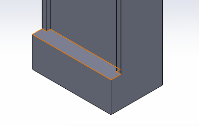
First, use Offset Entities to offset the sketch arc by 2mm. Make sure the “Select chain” option is unchecked so that the flat bottom is not offset.

  |
We manually offset the bottom by drawing 3 lines to connect the arc endpoints, keeping everything at right angles. |
 |
Use Smart Dimension to make the bottom 2mm thick as well. |
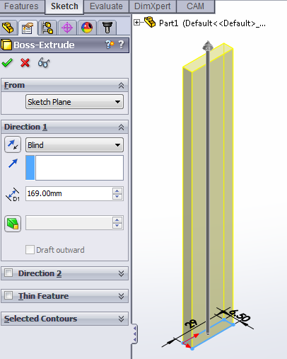
Extrude
Exit the sketch, and Extrude the shape 170 mm.


Fillet
Add a 1.1 mm radius Fillet on the two long edges of the actuator’s flat face.


Make thread grooves
Draw helix path
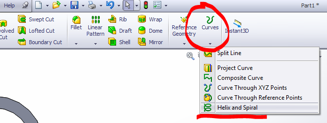
The thread grooves will be made using the Swept Cut feature. First, we have to make the path for the cut to follow, which is a helix. To create this helix, go to Curves > Helix and Spiral.
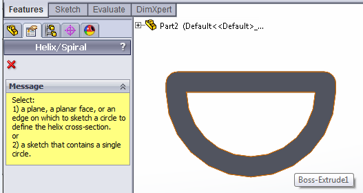
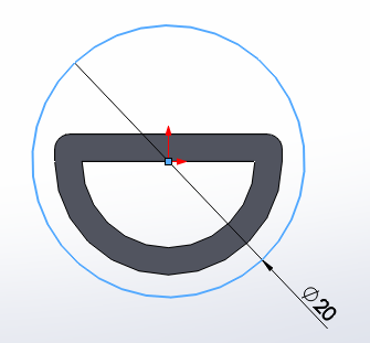
Select the bottom face of the actuator, and draw the base circle for the helix, which is 20mm in diameter and also centered at the origin.
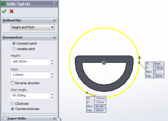 |
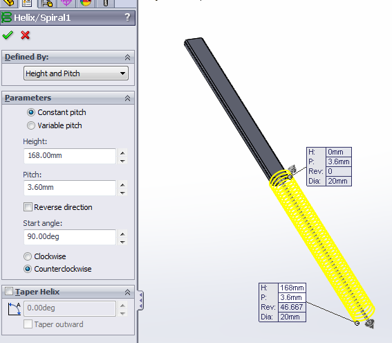
Exit the sketch and set the helix parameters.
|
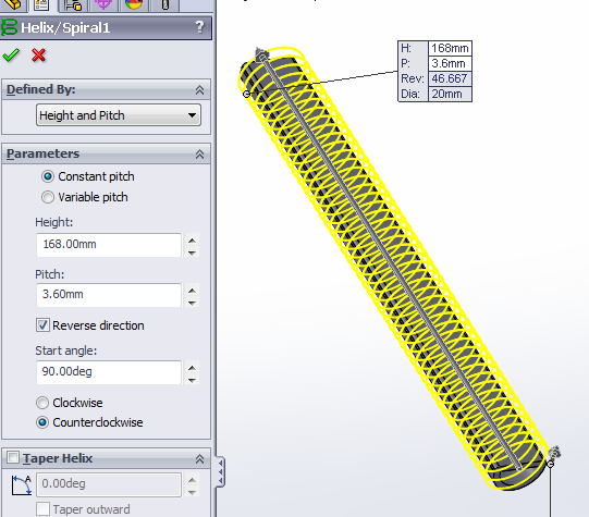
If the helix is going in the wrong direction (not surrounding the actuator), then check “Reverse Direction.” The result should look like the image on the right.
|
|
|
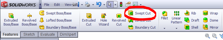
Swept cut
[Video: Swept cut for thread grooves]
|
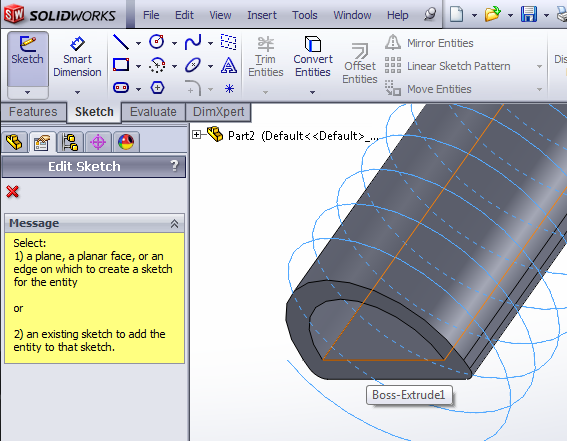
|
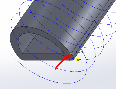
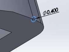
Now that we have the helix path, we can draw the profile for the swept cut. In the plane corresponding to the flat face of the actuator’s inner cavity, make a new sketch. |
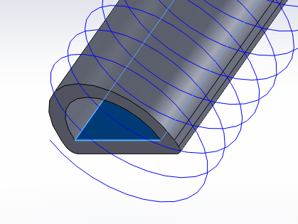
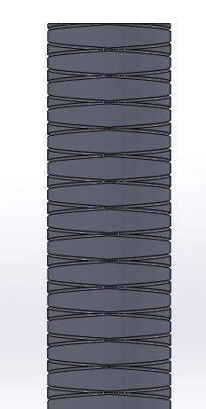
Draw a 0.4mm diameter circle, with its center aligned with the outer bottom edge of the actuator.
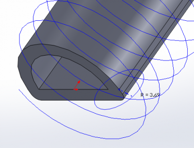
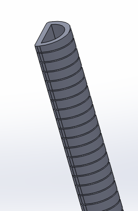
Using Swept Cut, use the sketches you just made and define them as the sweep profile and path. This will cut a series of grooves spiraling up the front of the actuator.
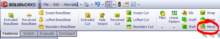
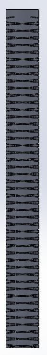
Mirror
[Video: Mirror for symmetrical thread wrapping]
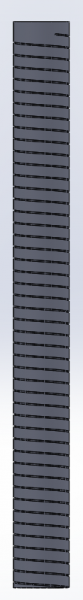
To get the other set of grooves, we can simply Mirror the swept cut we just made over the mid plane of the actuator, which corresponds to the Right Plane in this tutorial.
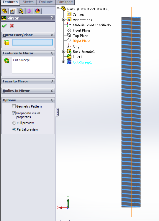
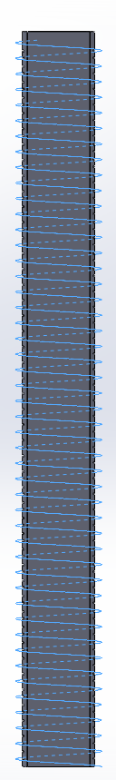
The result should look like this:
Make main mold
To make the molds, we use the Cavity feature, which enables us to do subtraction with bodies in an assembly. We have the molded actuator CAD part, but we also need the mold block we are going to subtract the rod from. The following section will cover making the main mold – we will make the top mold and cap piece later.
Make main mold block
The main mold starts out with a 29mm x 12.5mm x 169mm rectangular block which has 3mm x 3mm ridges to help with mold alignment and sealing.
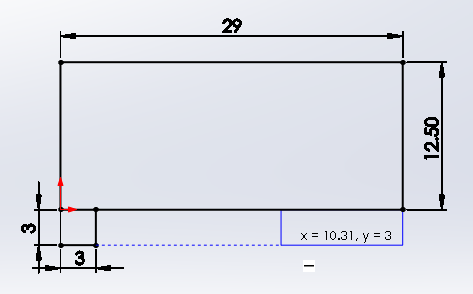 |
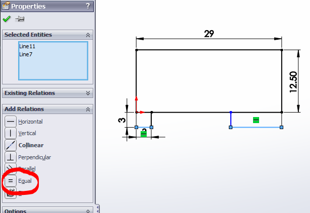
In the top plane, sketch a rectangle and Smart Dimension it to 29mm x 12.5mm. Next, draw a smaller attached rectangle and smart dimension it to 3mm x 3mm, then draw a rectangle of matching height on the other side (use the dotted line guide to make sure the heights are equal). |
Select the widths of the 2 small rectangles (hold down CTRL and click both segments). The properties panel should appear. Select "Equal" under the Add Relations section. The two rectangles should now be identical.
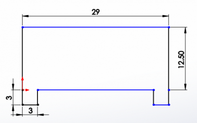 |
Use the Trim tool to delete the borders between rectangles so that you have one contiguous shape. |
 |
Exit the sketch and Extrude it 169mm. |
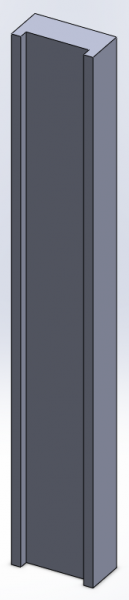
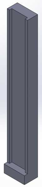
The result should look like this:
Add ledge
[Video: Add ledge to mold body]
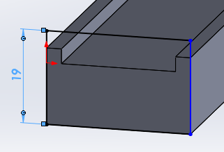 |
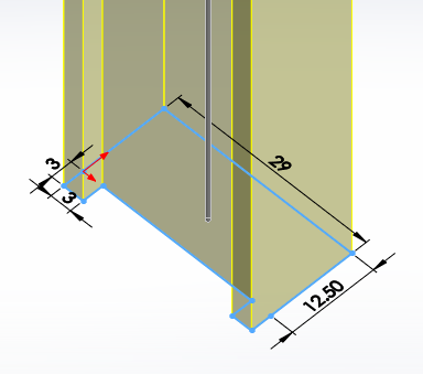
On the bottom face of the mold block, draw a rectangle that matches the width of the block and is 19mm high. |
|
|
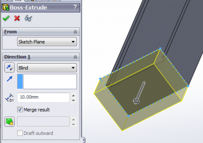
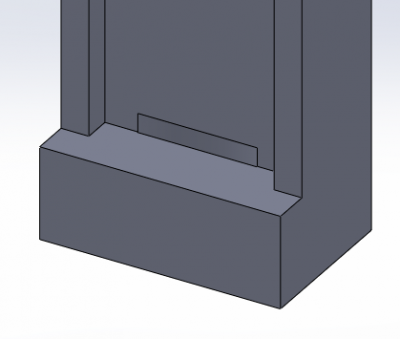
Extrude the rectangle 10mm, creating a ledge. |
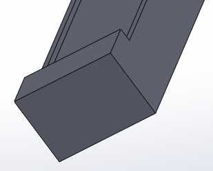
The result should look like this:
Add hole for inner rod
Now we have to cut a hole for the inner rod to lock into.
 |
Make a sketch on the newly created “ledge” at the bottom of the actuator. |
 |
Draw a Point at the midpoint of the ledge. |
  |
Use this point as the center of a 12.7mm diameter circle. |
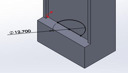 |
Using the same method as before (draw a diameter line and Trim), make this into a semicircle. |
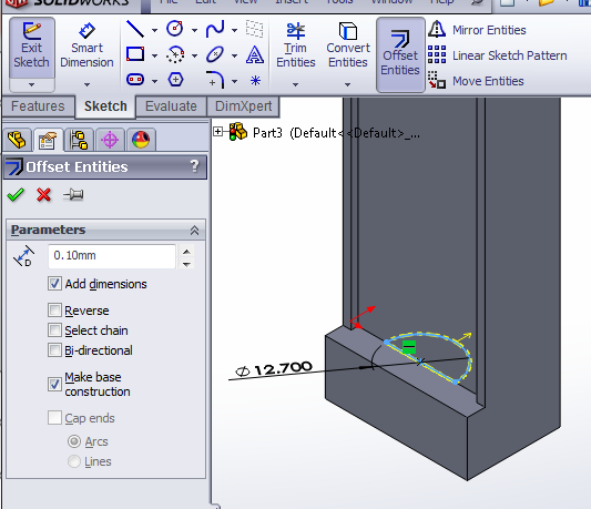
Next, we use Offset Entities to add 0.1mm for tolerance. This time we can offset everything, so use “Select chain.” Also check “Make base construction.”
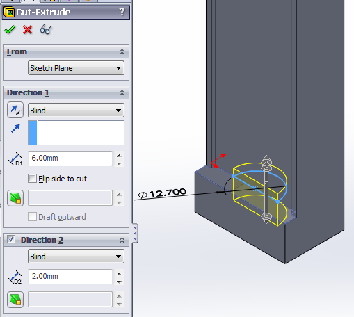
Using Extruded Cut, cut in both directions from the sketch plane: 6mm down and 2mm up.
The result should look like this:
Align mold block and actuator
[Video: Make interim assembly for main mold]
Save the mold block part, then create a new assembly. This will be the interim assembly used for the Cavity feature.
In the assembly, add the mold block and actuator. Position them with 3 mates:
- Coincident: bottom face of actuator and bottom lip of mold
- Concentric: inner actuator cavity and rod hole in mold block
- Parallel: flat side of actuator, flat of mold block
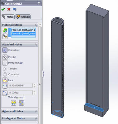
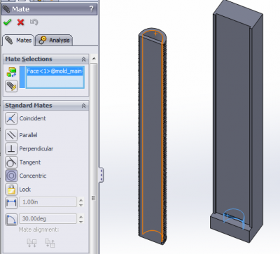
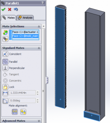
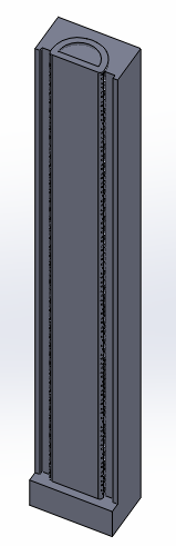
The final assembly should look like this:
Subtract actuator from mold block
[Video: Subtract actuator using the cavity feature to get main mold]
Now that the parts are properly positioned relative to each other, we can subtract the rod from the mold block with the Cavity feature.
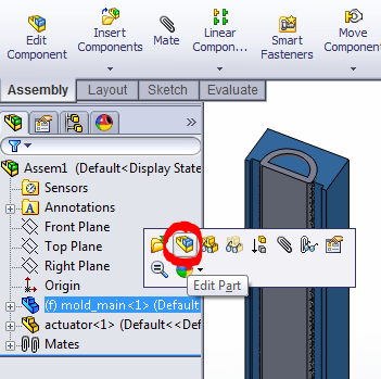 |
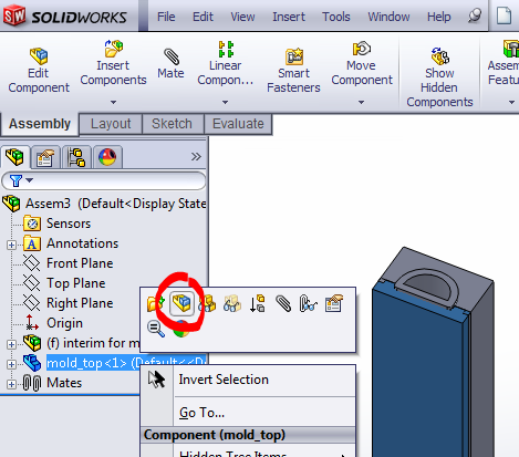
Save the interim assembly (but don’t close it yet). Click on the mold block in the FeatureManager design tree, then click the “Edit Part” button in the menu that pops up. |
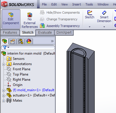 |
Now you are editing the mold block within the assembly. |
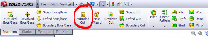
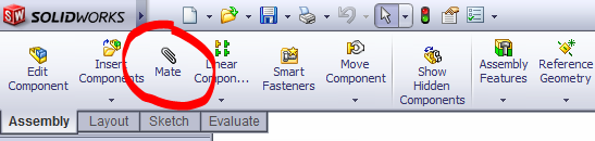
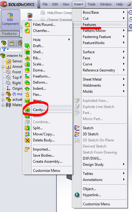
Now, use the Cavity feature (Insert > Features > Cavity). If it's not in the menu, go to Customize Menu and add it first.
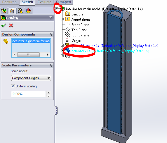
Select the Design Component, which is the part to subtract from the part you’re currently editing (the mold block). In this case, you want to subtract the actuator. To select it, expand the FeatureManager design tree and select the part corresponding the actuator.
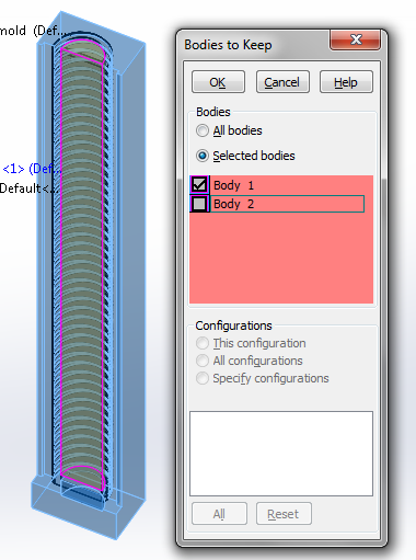
Click the check mark to complete the Cavity. A dialog will pop up asking about bodies to keep. This is because in addition to the mold block, there is another body created by the hollow space inside of the actuator. However, we don’t need this body for anything, so we select only the body corresponding to the mold block to keep.
Now that this mold piece is done, click the “Edit Component” button in the corner to return to the assembly.
Make top mold
Now we will make the 2nd mold half, once again using the Cavity feature. We make a solid rectangular block, then subtract both the actuator and the main mold piece from it. Once again, we make the basic part, then assemble it to properly position everything relative to each other, then use Cavity.
Make top mold block
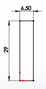
In the top plane, draw a 6.5 mm x 29 mm rectangle. Extrude it 169mm to get a long, thin rectangular prism. Save the part.
|
Align all parts
[Video: Make interim assembly for top mold]
Create another new assembly and save it as the interim assembly for the mold top. Insert 2 components: the thin block you just created, and the previous interim assembly. Position the components with 3 coincident mates (top, side, front).

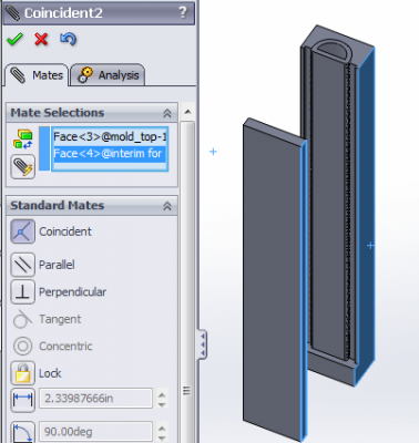 
|
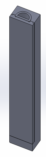
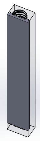
The result should look like this:
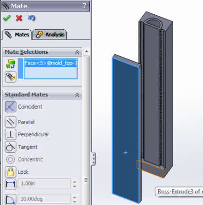
Subtract actuator and main mold
|
Once again, click on the mold part in the design tree and click the “Edit Part” button. |
Use Cavity (Insert > Features > Cavity). Once again, expand the design tree and select the component you want to subtract, in this case it’s the first interim assembly for the main mold. However, since you cannot select assemblies, expand the tree further and select the two parts (main mold and actuator) that make up the main mold assembly.
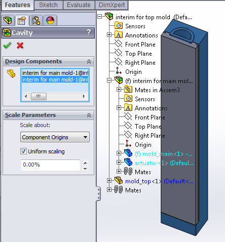
Click the checkmark to complete the cavity, and click the “Edit Component” button to return to the assembly.

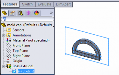
Make mold cap
The final part needed for the mold is the cap piece, which aligns the top of the inner rod during molding.
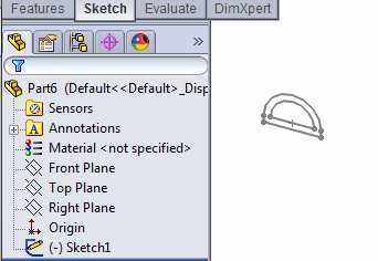
Get sketch for mold cap
To make the sketch for the cap, we can reuse the sketch from the actuator part file:
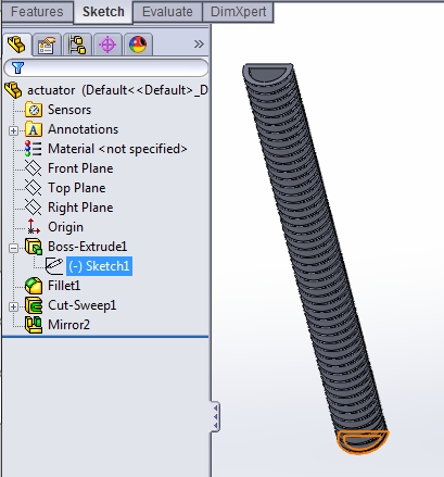 |
Open the actuator part file and expand the design tree so that you can see the sketch used to extrude the actuator body. |
 |
Create a new part file, and press CTRL+V to paste the sketch. |
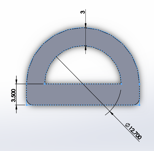
Finalize sketch
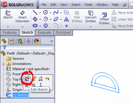 |
Edit the pasted sketch. |
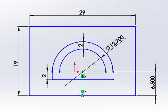
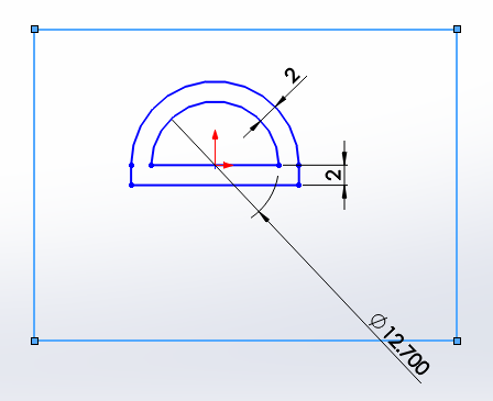 |
First, if it doesn’t show up already, smart dimension the 2mm wall thickness offsets to strictly define the sketch so we do not accidentally modify these values while making the following edits. Next, add a rectangle surrounding the sketch, which defines the edges of the mold cap. |
The rectangle doesn't have to be perfectly centered and dimensioned for the mold cap to work -- just make sure that there is a comfortable margin around the lip.
However, if you want the cap to look nice and flush with the rest of the mold, then dimension the rectangle to 29mm x 19mm, distance the inner flat face of the actuator 6.5mm from the bottom, and use Add Relations to vertically align the center point of the rod arc with the midpoint of the bottom edge of the rectangle.
Extrude selected contours
As this sketch has multiple closed contours, when Extruding it we only extrude sections of it at a time using the “Selected Contours” options.
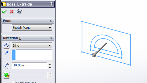
  |
First, select the “D” shaped contour and extrude it 1.5mm. |
 |
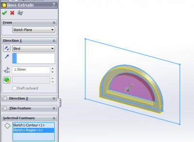
Select the sketch again in the design tree (it is now located under an extrude feature), then click Extrude in the Features toolbar to reuse it. |
This time in "Selected Contours", select both the ‘D’ and the outer region of the sketch. Extrude it 3.5mm in the opposite direction from before (click the button with arrows next to “Blind” to reverse direction).
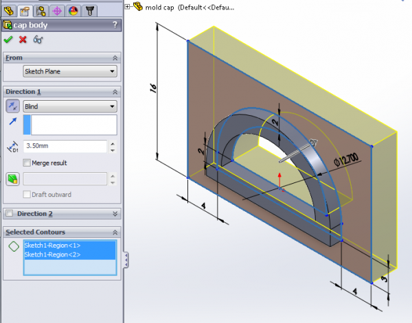
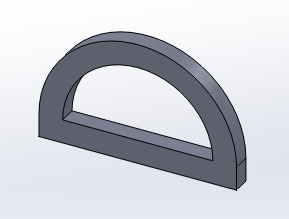
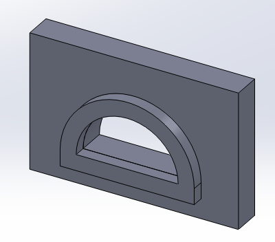
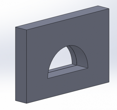
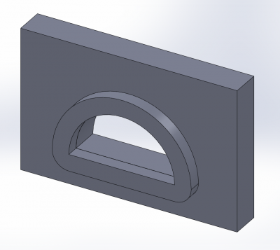
Complete the extrude. The final mold cap should look like this (front and back):
Fillet the outer corners of the lip, to match the fillet of the actuator (and corresponding cavity in the mold) so that the cap will fit. Alternatively, these corners can easily be cut or filed off after printing.
Make outer skin molds
We can make the molds for the outer skin repeating same process we just followed, but adjusting some of the dimensions. Instead of remaking everything, the easiest option is to make copies of the solid model files we just created, and then modify some of the dimensions:
- Make a copy of all the files in a new folder by opening the interim assembly for the top mold (which contains all the parts except for the mold cap) and using File > Pack and Go. You should use the "Add Prefix" option to differentiate the new files. Do not just copy & paste files in Finder/Windows Explorer, as this will mess up your references!
- In the newly copied folder, open the actuator file. Get rid of the thread grooves by deleting the Mirror and Swept Cut features (check the "Also delete absorbed features" option to clean up the associated sketches).
- Increase the wall thickness by however thick you want the outer skin to be. A 1mm increase is recommended, with a 1.5mm increase on the bottom to accommodate the fiberglass layer. Change the smart dimensions accordingly and rebuild the part.
- Open the interim assembly for the top mold, rebuild, and save. The main and top mold pieces will update themselves to fit the new actuator.
- The mold cap needs to be updated manually, but it is very easy: open the mold cap file, change the wall thickness smart dimensions in the sketch, and rebuild.