Fabrication
The general fabrication process for SDM parts is as follows:
- Make a mold defining geometry of a subsection of your
- Position components in the mold
- Pour/inject material into mold and cure
- Repeat steps 1-3 as necessary. the subsections that have previously been cast now become components embedded in a new larger mold.
- Remove part from mold
The specifics of the process depend on the complexity of the desired final SDM part. There are 2 general methods: open-top molding and closed-top molding.
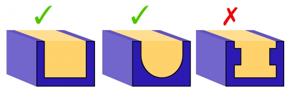
Open-top molding works for simpler geometries. Molds are made by milling pockets into wax blocks, so the part shape is limited by the fact that the inverse shape for the mold is millable. For example, the left-most shape in the below image is simple to make, the center one would require 3D CNC milling but is still possible, while the last shape cannot be made.
In addition, since the casting material is liquid and poured into the mold, the top of the part will be flat, as that is how the liquid material settles.
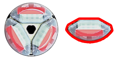
Closed-top molding allows for more complex part geometries. For example, the fingers used in this case study needed to be compact and fit within a cylindrical delivery tube. This meant that the fingers had a cross-section with undercuts on both sides, highlighted in red below, which was not achievable with open-top molding. However, a 2-part closed-top mold was able to make this geometry.
Mold design for closed-top molding is more complicated -- molds have to be 2-part so that the final result can be removed, and additional features such as injection ports and sprue holes have to be included. The molds also need to be 3-D printed as they are impossible to machine.
Open-top molding
The open-top molding process is used to create monolithic multi-segment fingers with simple morphologies. The following is an illustrated step-by-step tutorial on using SDM to manufacture a simple 3-jointed finger using an open-top wax mold. In the diagrams below:
- RED indicates a milling/machining step,
- GREEN indicates a component placement step, and
- BLUE indicates a filling step.
Personal protective equipment (lab coat, safety glasses and latex or nitrile gloves) should be worn at all times. Filling and mixing should be performed inside a fume hood.
Download a .zip file containing the Solidworks part file as well as g-code for the 2 machining steps HERE
MINIMUM Materials
- Wax blank (for example, MSC.com)
- High-modulus plastic for stiff segment. Here we will use Task-9, a 2-part urethane plastic from Smooth-On.
- Low-modulus elastomer for soft segment. Here we will use PMC-780, a 2-part urethane rubber from Smooth-On.
- Tubing for cable routing. For example: High-Pressure PEEK Tubing, .020" ID, 1/16" OD, .021" Wall Thickness, Orange (McMaster P/N: 51085K45)
- Cable for actuating finger (several material options here, such as steel wire, Nitinol wire, or Kevlar thread)
- Any fastening materials (application-dependent). Here we will use a 10-32, 3/4" screw and a 10-32 hex nut.
- Modeling clay/crafter's clay
STEP 1: Milling
Starting with a wax blank, mill pockets for the stiff segments, as well as any pockets/channels to hold components that will be embedded within the stiff elastomer. Invariably this will include a cable sheath (plastic tubing), and it could also include any embedded fasteners (screws, nuts) or sensors. You should select an endmill with a diameter equal to the smallest feature you need to cut. In this case the smallest feature is the pocket for the cable-routing tubing which is 1/16" wide, so we will use a 1/16" endmill.
Recommended cutting speeds for machinable wax are (from http://www.machinablewax.com/technical.php):
- Roughing: Spindle speed 3,000 rpm at ~ 100 inches per minute
- Finishing: Spindle speed 8,000 to 10,000 rpm at ~ 40-100 inches per minute
- Depth of cut: roughly 1/2 Tool Diameter

STEP 2: Placement
Place components that you wish to embed in the finger inside the mold. In the figure below, these components include 1 cable sheath, one flathead screw and 1 nut to locate the screw within the proximal-most segment. These components will be embedded within the stiff elastomer. Place crafter’s clay into any small areas where you don’t want the elastomer to fill (for example, on the portion of the screw threads that will be outside the finger, over the cable tubing in between each finger segment).

STEP 3: Filling
Thoroughly mix Task-9 parts A and B (in a 1A:1B ratio by volume). Be wary of the 'pot life' (i.e. working life) of the plastic; for Task-9 this is about 7 minutes. Slowly pour the mixture into the pockets until the mixture is flush with the surface of the mold. Place mold inside a vacuum chamber to degas the elastomer and wipe away any bubbles from the surface. Try to ensure that no elastomer ‘bleeds’ over on the top surface of the wax mold. Once sufficiently de-gassed, place entire mold in a safe place and let it cure for a couple of hours at room temperature.

STEP 4: Milling
Machine pockets for the flexible segments. The profile shown below is a ‘dogbone’ profile to ensure positive engagement between the flexible and stiff segments (although other profiles are possible). This time, we want to use speeds and feeds appropriate for the stiffest material which is the Task-9 polymer, not the machinable wax. Recommended speeds/feeds for Shore D 85 polyurethane:
- Roughing: Spindle speed 1600 RPM at 40-60 inches per minute
- Finishing: Spindle speed 5000-10000 RPM at 100 inches per minute
- Depth of cut: roughly 1/2 Tool Diameter

STEP 5: Filling
Mix PMC-780 parts A and B (in a 2A:1B ratio by weight or by volume). Fill pockets with the mixture and follow the same procedures described in Step 3 to ensure adequate degassing and curing. Set aside for the recommended curing time.

STEP 6: Release
Once fully cured, the assembly is ready to be released. The wax blank used in this lab is 1.5" thick, with the finger only occupying 0.5" of the thickness. Use a bandsaw to take down the wax blank thickness to 0.75" or so and cut out some wedges in the wax around the finger to act as stress concentrators. Use a vice to (carefully) compress the wax mold and break it off around the finger, ensuring that you minimize the amount of torsion being placed on the flexible joints as they can tear. Once the finger is released, trim the excess non-embedded portions of the cable sheath (from the ends and from in between the stiff segments). Feed the cable through each joint and tie off at the end. The finger is complete!

| SolidWorks part file + mold milling g-code | 284 KB |
Closed-top molding
For fingers with more complex cross-sections that cannot be achieved with open-top molding, we can 3-D print two-part, closed-top molds. A complication of the closed-mold approach is the inability to machine the pocket for the flexible joint material. As such, a separate molding process must be performed to mold the flexible joints independently. This section does not provide a definitive guide to mold design; however it does present a case study and describes factors of the closed molding process that must be taken into consideration.
Considerations for closed-top molding
The fabrication process for closed-top molds is slightly different from that for open-top molds:
1. Mold Release: Apply liberally. This is very important. Unlike wax, 3D-printed resin cannot be broken and easily separated from the molded finger. Also spray on the clamping surface so any elastomer leakage doesn’t lock the mold shut once cured.
2. Component Placement: Your molds should contain features to align any components you want to embed in the finger.
3. Closing the Mold: Clamp tightly with socket-head cap screws.
4. Degassing: In contrast to the open-top mold, it is best to degas the elastomer before injecting into the mold. Limited exposure to the air makes it difficult for bubbles to escape once the fluid is injected into the mold, creating voids in the finished part.
5. Filling: As the mold is closed, you will likely need to use a syringe to inject fluid into the segment cavity. This must be done very carefully and slowly so you don’t introduce bubbles into the mold. If possible, use a translucent material as your mold material so you can visually inspect the quality of the injection. Depending on the viscosity of the fluid, gravity might not be enough to adequately fill tight spaces within the cavity. A good technique is to design inflow and outflow sprues into the mold, wherein the fluid is injected into the segment cavity at one location, and allowed to eject from the cavity at another location. This allows the fluid to circulate and leverages the pressure differential to fill the cavity.
Closed-top mold design
The following image shows the features of a closed mold used to fabricate a 3-jointed SDM finger with an embedded pressure sensor.
|
|
|

Closed-top molding steps
Step 1: Mold the individual flexural components first. This can be done using an open-top molding process.
  |
 |
Step 2: Place the various flexural components, as well as the cable sheath and any sensors/wiring, into the master mold. |
 |
Step 3: Close the master mold and tighten securely with screws. |
 |
Step 4: Carefully introduce high-modulus elastomer into each compartment using a syringe. |
