Fabrication
This section breaks down the necessary steps to mold and assemble the EGaIn sensor described previously. The sensor consists of two halves that are molded separately and then bonded together. The molding and bonding processes are assisted by an oven and spin-coater to speed up the curing and bonding procedures. EGaIn is then injected into the channels inside the sensor and electrical wires are attached. An overview of this process is given below.
Overview of steps to be taken
|
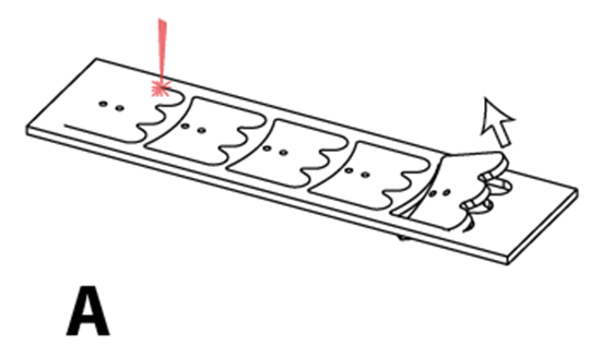
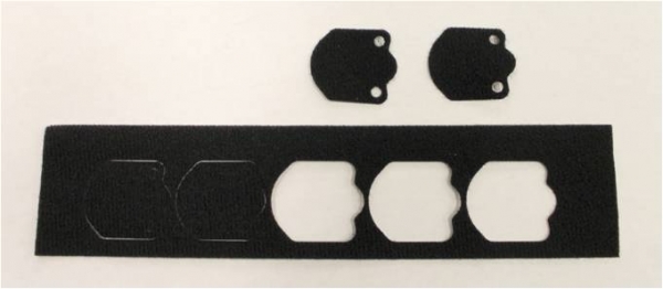
(A) Velcro is laser cut into desired shape.
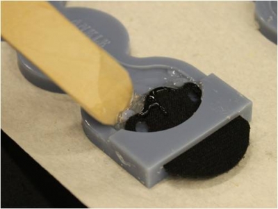
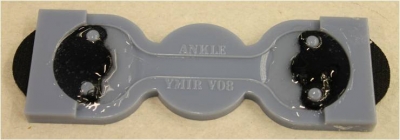
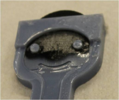
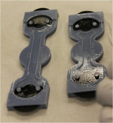
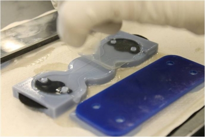
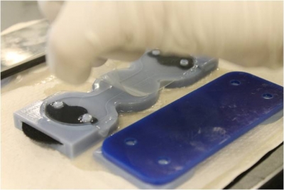
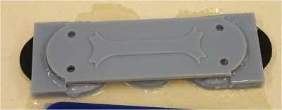
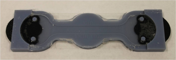
(B) Velcro is placed in the bottom-half mold and encapsulated in stiff silicone rubber.
(C) The encapsulated velcro in the bottom-half mold and the top-half mold are cast with soft silicone rubber.
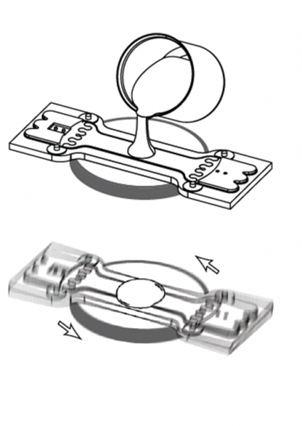
(D) After curing the bottom-half mold, a small amount of soft silicone rubber is spun on to it to act as an adhesive layer for lamination.
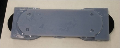
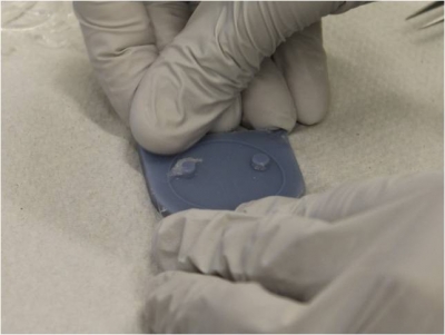
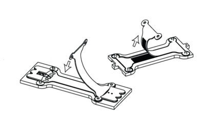
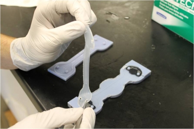
(E) The top-half sensor is demolded and laminated to the bottom-half.
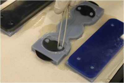
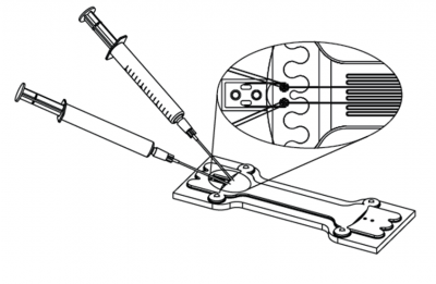
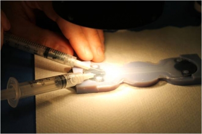
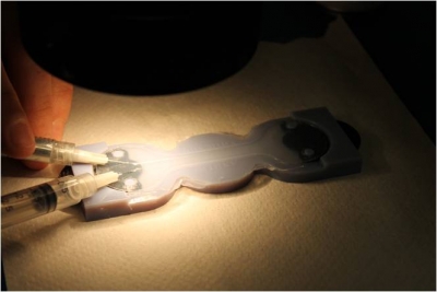
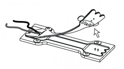
(F) Liquid metal alloy is injected into the microchannels with one needle while a second is used to evacuate the entrapped air.
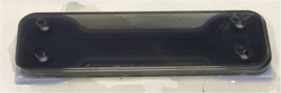
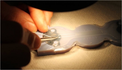
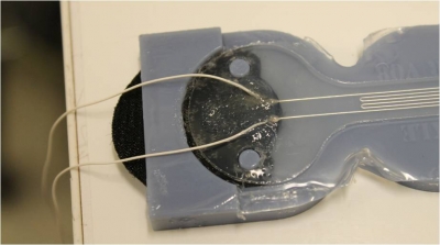
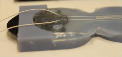
(G) To complete the sensor, wires are inserted into the soft elastomer and encapsulated with rigid epoxy for strain-relief.
|
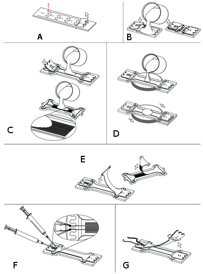 |
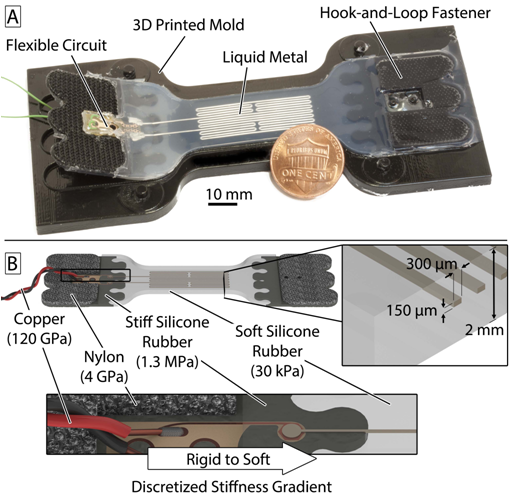
Diagram of full sensor
Overview of Mold
|
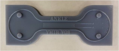
Top mold (mold, acryllic plate and transparency shown) |
|
| Top mold: This half of the mold has the negative impression of channels that will contain EGaIn. Transparency and acryllic plate used to close the mold are shown in the bottom picture. | |
|
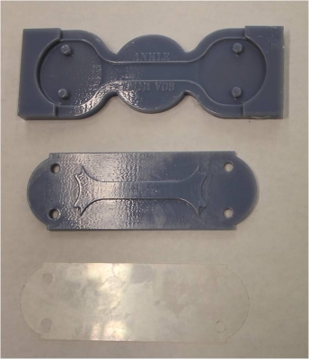
Bottom mold:
When molding the soft elastomer, use the transparency and the flat side of the top plate.
When molding the stiff elastomer, use the raised side of the acrylic plate.
|
Bottom mold (mold, top plate and transparency shown) |
Bill of Materials
This section will give a list of items that are used in this project with selected links to suppliers. You can download a more detailed Bill of Materials sheet here.
Note: Many of the items listed are just examples and you can use your own discretion to substitute parts which are easier or cheaper to obtain.
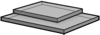
Mold Components
 |
|
| Top Mold | Acryllic plate and Transparency film |
 |
|
| Bottom mold (mold, top plate and transparency shown) |
Click here to download the .STL files needed to 3D print the molds for this sensor.
Click here to download the .DXF files needed to laser cut the transparencies and plates.
If you would like to modify the molds click here to download the SolidWorks part files.
Polymer Materials
 |
 |
 |
|
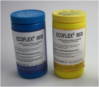
Soft silicone rubber (EcoFlex 0030, Shore OO-30 hardness, E = 30 kPa) |
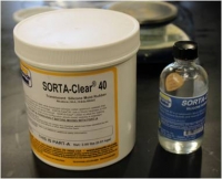
Stiff silicone rubber (SORTA Clear 40, Shore A-40 hardness, E = 1.3 MPa) |
Mold Release (Ease Release 200 works well) |
Other Materials
 |
 |
 |
|
Velcro material, Loop 3008 type* |
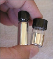
Eutectic indium gallium alloy (EGaIn). Need ~100 uL per sensor though it depends on channel geometry. |
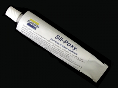
Silpoxy silicone adhesive |
|
|
|
|
|
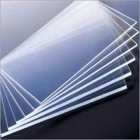
Transparency film |
Acrylic (1/4" thick) |
*Type selected because it is very thin (low profile)
Tools & Hardware
 |
 |
 |
|
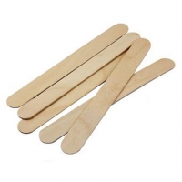
Tongue Depressors |
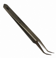
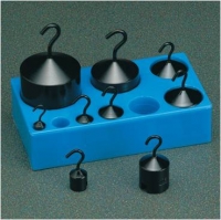
Tweezers | Weights |
 |
 |
 |
|
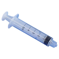
2 small syringes (1.5-3 mL) |
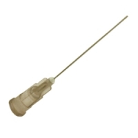
2 needles (27 gauge) |
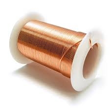
Electrical wire** |
 |
||
|
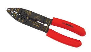
Wire Strippers
|
**Smaller diameter is better. Here we use 36 AWG copper wire.
Equipment
 |
 |
 |
|
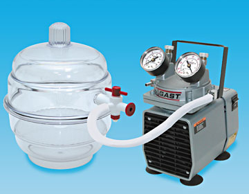
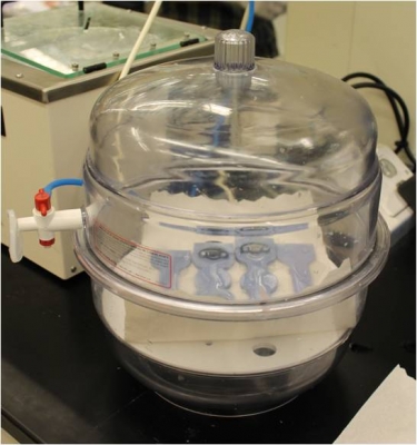
Vacuum chamber |
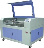
Laser cutter |
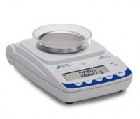
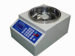
Mass scale |
 |
 |
 |
|
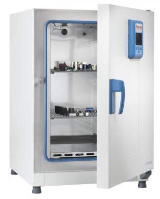
Lab oven |
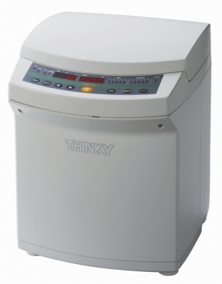
Centrifugal mixer |
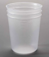
Mixing cups |
 |
 |
 |
|
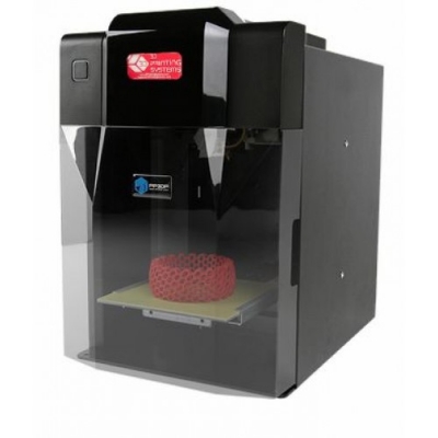
3D Printer*** |
Spin-coater |
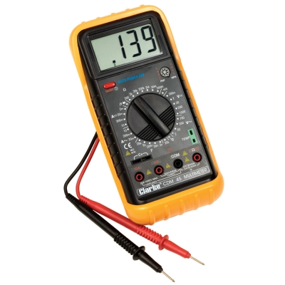
Multimeter |
 |
||
|
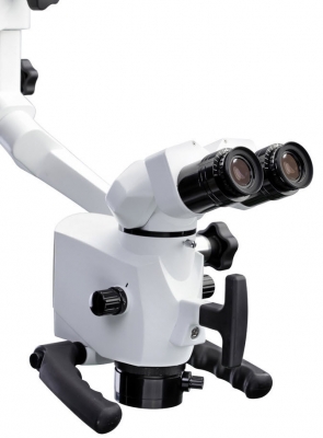
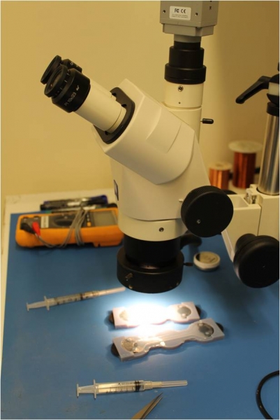
Microscope (optional) |
***Minimum need 10x better than dimensions of your structure. i.e. object spatial res. On micron level, but smallest features are 100 microns. Same for FDM. Aim for few hundred microns wide/tall
| SRT_EGaIn3DPrinterFiles.zip | 1.24 MB | |
| SRT_EGaInLaserCutterfiles.zip | 9 KB | |
| SRT_EGaInMoldModel.zip | 2.1 MB | |
| EGaIn Detailed BOM.xlsx | 13 KB |
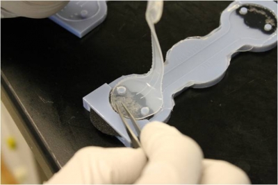
Step 1: Prepare Velcro Fasteners
|
The first step involves laser cutting the shown pattern from Velcro sheets. Laser cut the Velcro with the fuzzy loop side facing upwards, not the hook side. The .DXF files used to create this pattern can be found here.
Note: Make sure to cut 2 pieces for each sensor you want to make.
|
 |
|
 |
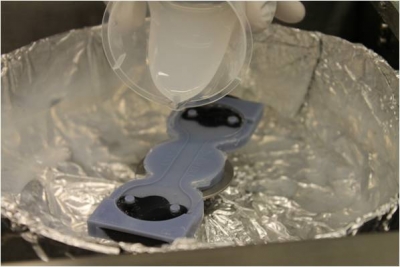
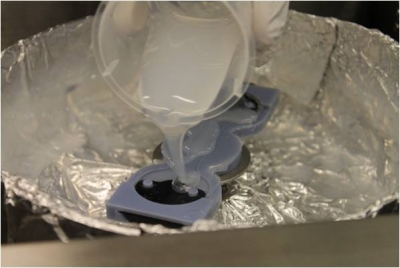
Step 2: Mold Stiff Ends
|
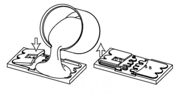 |
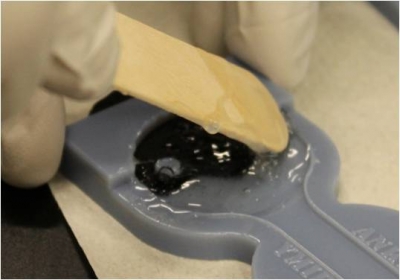
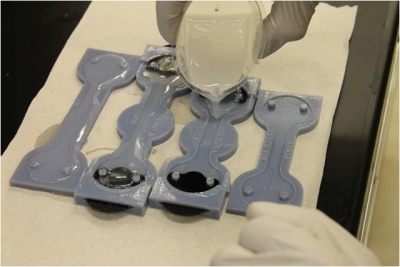
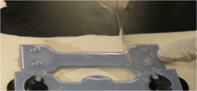
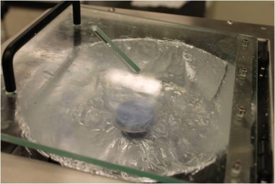
Pour stiff rubber
 |
|
 |
|
 |
|
 |
|
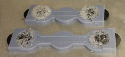
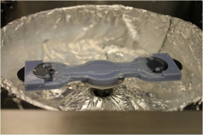
Degas elastomer
 |
|
 |
|
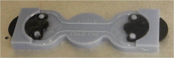
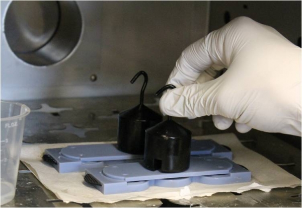
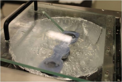
Seal and press mold
 |
|
 |
|
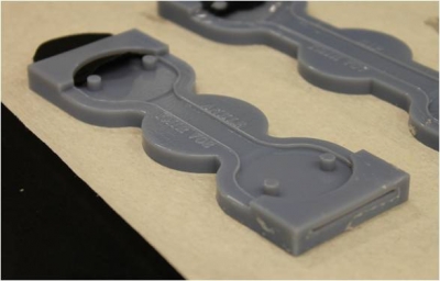
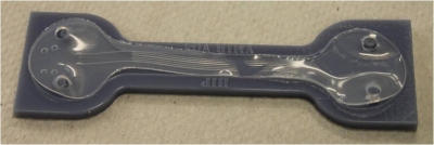
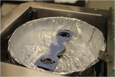
Check for defects
 |
|
 |
|
Step 3: Mold Top and Bottom Layers
|
 |
Pour EcoFlex and Degas
 |
|
 |
|
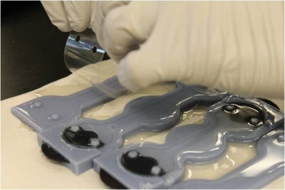
Add Transparency
|
|
 |
 |
 |
 |
 |
Note: There is a transparency for both the top and bottom mold and they both need to be placed down at this time.
|
Cover Mold
 |
 |
|
|
Demolding
 |
|
 |
|
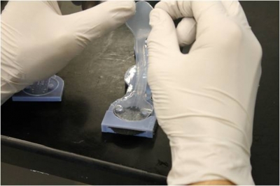
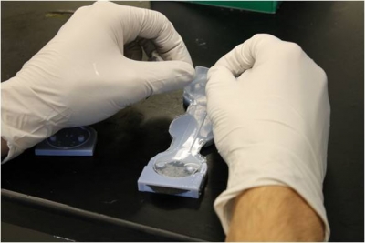
Step 4: Bond Top and Bottom Layers
|
 |
Add Adhesive Layer
 |
|
 |
|
 |
|
 |
|
Set New Layer in Oven
 |
|
 |
 |
Align Layers
 |
|
 |
 |
 |
|
 |
|
 |
|
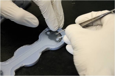
Step 5: Inject EGaIn
Setup
|
The next step involves injecting the EGaIn into the hollow channels of the sensor. In order to do this, you will need 2 syringes with 27-gauge needles.
|
 |
Injecting
 |
|
 |
 |
|
|
Step 6: Plunge Wires
Prepare and Insert Wires
 |
|
Test and Seal
 |
|
 |
|
Step 7: Demold
|
 |