Design
The control board is intended to be as modular and reconfigurable as possible, so that users can modify it to suit their particular design needs. This documentation will cover the fabrication and operation of a control board for pneumatic (air-operated) systems. The same guidelines will apply for a hydraulic (water-operated) control board, however it will need to use different components (discussed below).
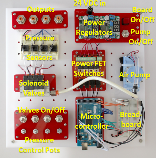
The board consists of:
- A miniature diaphragm pump as the air source, which can provide up to 30 psi of pressure.
- Solenoid valves which can direct the flow of air in the system.
- Pressure sensors which can provide feedback on the behavior of the system.
- A microcontroller (Arduino Mega), which enables users to interface with the hardware using their own computer via a USB cable (serial port) connection. Users can control various components or get sensor readings in this way, and write programs that use these elements for more advanced control of soft actuators.
- Switches and MOSFETs that can control the opening and closing of the solenoid valves.
- Rotary potentiometers ("pot") that control the pressure in the system (each controls the pressure in one channel).
- A breadboard to allow components to be added to the system.
- Power jacks.
- Various connectors, fixtures, and tubing.
The base structure of the control board is a sheet of acrylic with a laser-cut "pegboard" design (the white board in the above image), which makes it easy to reconfigure, add, or remove board components. Most of the components are mounted to laser-cut acrylic parts (the red pieces in the above image) which help to organize the board and also make reconfiguring the system easier.
On the next page, we discuss some options and alternatives for modifying the board to best suit your needs.
Variations
Variation: Operating Fluid
The choice of operating fluid largely depends on your application. Water and air each have their own advantages and disadvantages as an operating fluid. For example, a pneumatic system can draw air from the environment (so the system doesn't need a reservoir) and any leaks that occur will not cause a mess. However, air is a compressible fluid and this can mean that it takes more energy for the pump to compress the air to reach the desired pressure. Furthermore, for some medical applications, particularly when an actuator will interact with blood, using air presents serious safety concerns.
The opposite is true for hydraulic systems: they require a reservoir and leaks will result in water spillage which may cause problems, but the system may be more energy efficient and water may be a safer choice for some applications.
As mentioned on the previous page, we describe a pneumatic control board here but it is relatively straightforward to use these instructions to build a hydraulic board. The main difference to consider is the selection of components. The following items on the Bill of Materials should be changed if you want to build a hydraulic control board (in most cases the vendors offer hydraulic versions of these parts):
- Pump
- Valves
- Pressure sensors
- In addition, a water reservoir will need to be added.
All other parts of the control board should stay the same, and the general fabrication and operation instructions provided here should apply.
Variation: Alternative Components
Most of the components on the board (and the particular models and brands of each component) can be replaced with alternatives based on cost, availability, and performance. We have found parts and suppliers specified here to be easy to obtain in the United States, but there may be better local options in other parts of the world. The part specification we provide can be useful in finding alternative components. We strongly advise you to get in touch with vendors directly to discuss your particular needs; most vendors can provide design expertise in their area and this can save you a lot of time and money.
Here we discuss some particular alternatives, but this list is by no means exhaustive:
- The MOSFETs can be replaced with motor drivers such as these.
- There is a massive variety of solenoid valves available. Some of these are designed for use with specific manifolds so before you buy any be sure to check if they are only compatible with certain setups. On that note, the use of a manifold can help to keep the board compact and well-organized, by eliminating the need for multiple branchhes of tubing.
- When selecting a pump, the important parameters to consider are power consumption, weight and volume, operating pressure, and flow rate. These will depend on the types of applications you are interested in. For example, we have chosen a pump that is small and light and has relatively low power consumption (compared to less expensive pumps). We chose this pump so that the board could be modified for portable applications. If, however, you plan to always use the board as a static bench-based platform then the weight, size, and power consumption will be less of an issue and you can probably find a cheaper pump that will suit your needs. For the fluidic actuators described on this site we have found that an operating pressure of 30 psi and flow rate of about 1 SLPM is sufficient. Again, these values depend on your applications.
Variation: Pressure Regulation
As mentioned above, the current design uses MOSFETs to control the switching of the solenoid valves. This setup makes it possible to use pulse width modulation (PWM) to control the pressure of the fluid passing through these valves. During PWM, high-frequency pulses are sent to the solenoid valves, opening and closing them rapidly. By varying the length of these pulses, the amount of time the valve is open or closed is adjusted, and therefore the output pressure is adjusted.
The drawback of using PWM on the control board is that it is less straightforward to set up. For beginners with relatively little electronics and programming experience, this is not the easiest method to start with. The other option for pressure control is to use a pressure regulator. While being easier to use, pressure regulators can be expensive and allow for less control of the system. Using a single regulator allows you to vary the pressure of the whole system, but if you want different pressure in different parts of the system (e.g. different pressures for different actuators) then you need a way to control the pressure at each valve. PWM has the advantage that each valve is individually addressable, which solves this problem. However if that isn't a problem for your system, then a pressure regulator might make sense.
Variation: Sensors
Sensors can easily be added to or removed from the board without affecting its performance. The choice of sensors again depends on what types of applications you are interested in.
- A flow sensor can probably be added to monitor flow conditions.
- The breadboard allows easy interfacing of additional sensors. For example, a previous project team added a gyroscope to track the motion of their fiber-reinforced actuator. Other users have embedded flex sensors in their actuators to track bend angle.
- On the other hand, if you wish you could build a control board with no sensors at all.