Assembly
|
This section lists the parts needed to build your own pneumatic control board, and gives an overview of the assembly steps involved. See the previous section for a discussion of alternative components you might want to use, for example if you need to use water instead of air as your operating fluid. The overall assembly process will remain the same. Drawing files (.dxf) of the laser cut acrylic parts can be downloaded by clicking here, and the Arduino code we will use can be downloaded by clicking here. |
 |
Building the board involves some basic soldering. If you have never soldered before there are many useful introductory tutorials online. The video below (taken from this tutorial from SparkFun) gives a good introduction to the basic techniques and equipment for soldering.
| Control Board DXF Files.zip | 83 KB | |
| Control Board PWM Code.txt | 2 KB |
Bill of Materials
This section will give a list of items that are used in this project with selected links to suppliers. You can download a more detailed Bill of Materials sheet here.
Note: Many of the items listed are just examples and you can use your own discretion to substitute parts which are easier or cheaper to obtain.
Major Components
|
|
|
|
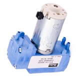
Miniature Diaphragm Pneumatic Pump |
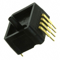
Pressure Sensor (x4)
|
|
|
|
|
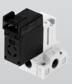
Solenoid Valve (x4) |
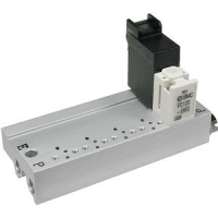
Manifold |
|
|
|
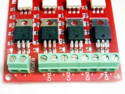
Power MOSFETs: 4 Opto-Isolated Power FET Switches
|
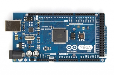
Arduino MEGA
|
|
|
|
|
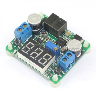
Power Regulator (x2) |
Toggle Switch (x6) |

For part and vendor information not show on this page refer to the Control Board Bill of Materials excel file. This excel can be downloaded here.
Base
These parts simply hold the above components in place. Use a laser cutter (make sure you are trained first!) to cut these pieces out of acrylic sheets. We use 3mm acrylic for all parts except the base board (6mm acrylic). Cut 2 copies of the base board. Download the .dxf files for cutting here.
|
|
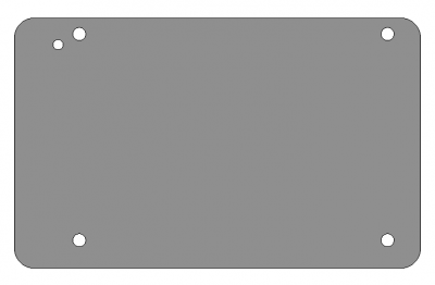
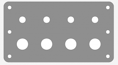
| Output ports | Manifold |
|
|
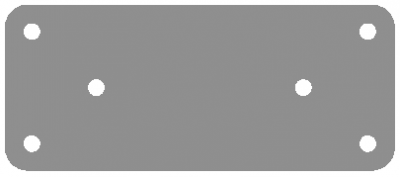
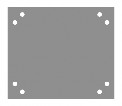
| Arduino MEGA | Switches |
|
|
| MOSFETs |
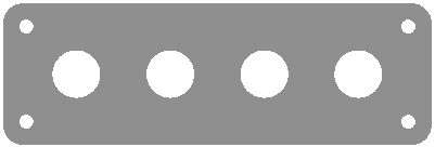
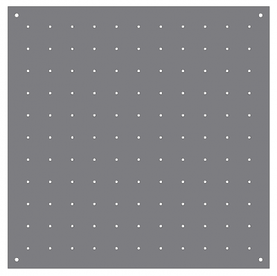
Base board (12"x12" / 300mmx300mm) |
|
|
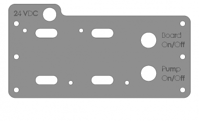
| Power |
| Control Board DXF Files.zip | 83 KB | |
| control_board_v2_bom_8-16edit.xlsx | 33 KB |
Assembling the Board
Mounting
At each corner of the baseboard, install a standoff using a single screw with a plain washer. This elevates the board to make room for the wires and connections underneath.
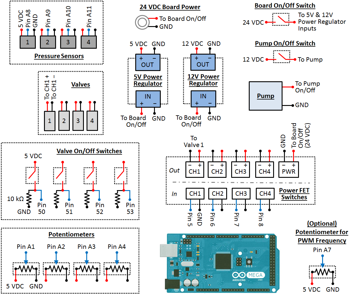
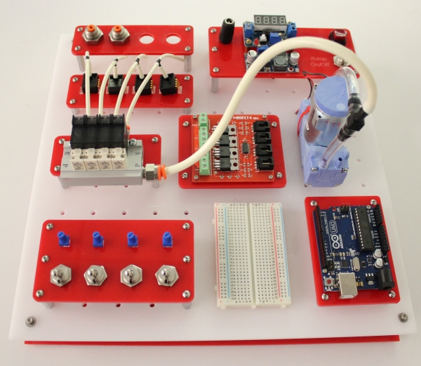
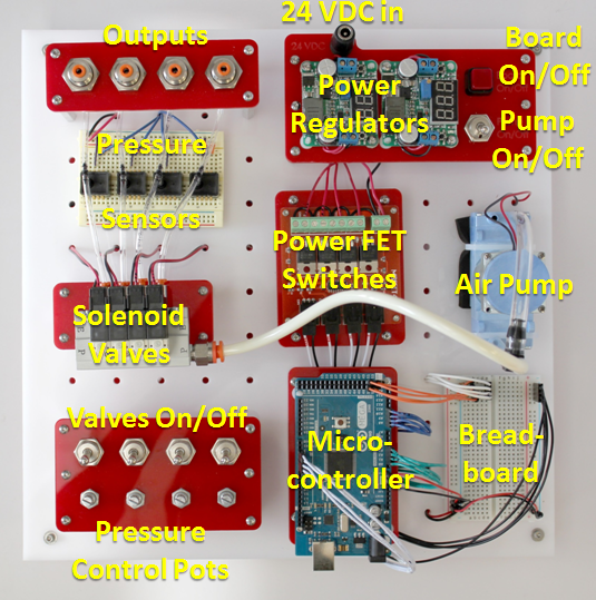
Solder any necessary wires to all the electronic components (follow the data sheets and the below wiring diagram). Using heat shrink tubing may also be a good idea to prevent shorts. Next, mount all the of the components onto the baseboard, following the image below. Use zip ties, screws, washers, nuts and spacers wherever needed. Connect the air flow between components using appropriate tubing.
Wiring
Now that all the components are in place, they need to be connected to each other, following the wiring diagram below. A good place to start is by connecting all the components to power. Use red and black wires to represent voltage supply and common (ground), respectively. It may be helpful to use a bus to manage the various power wires.
When connecting signal wires, be careful not to mix up the Arduino's digital and analog pins (analog pins are prefaced by 'A'). Use the breadboard as an intermediate between the components and the Arduino to help keep all the wires organized. You can also connect 5 VDC and ground to the Arduino's Vin and GND pins, respectively, so that it remains powered even if the board is not connected to your computer via USB.
Before connecting the control board to power, make sure there are no short-circuits. If the board doesn't work properly at first, use a multi-meter to diagnose the problem and double-check your wiring. After connecting all the power plugs, make sure none of the components are getting too hot!