Fabrication
As mentioned previously, there are many variations of designs and materials for dielectric elastomer actuators, which can require different techniques to create. The following section provides step by step instructions on the manufacture of a circular dielectric elastomer actuator on a rigid frame, made with VHB 4910 as the dielectric and electrodes made of carbon grease.
The dielectric elastomer used in this documentation is VHB 4910 because it is a sticky tape which can adhere to the acrylic frame on its own. If other materials are used for the membrane, clamps or glue may be used to attach it to the frame.
Process Overview
The manufacturing process can be divided into the following steps:
1. Prestretching of the membrane onto the rigid frame.
2. Painting of the active area with carbon grease.
3. Application of copper leads.
4. Connecting active area with copper tapes.
Get Started
First visit the Bill of Materials page to make sure you have the necessary materials and then continue on to Step 1 to begin building your own actuator!
Bill of Materials
Materials
|
|
|
VHB 4910** |
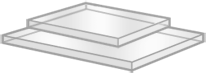
Acrylic to make frame |
|
|
|
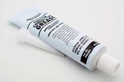
Carbon grease |
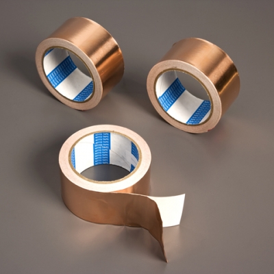
Copper tape |
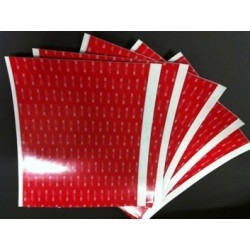
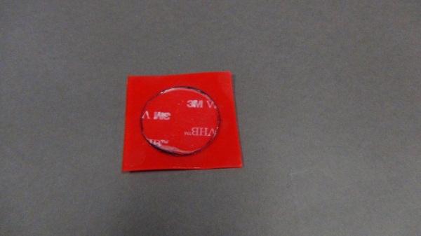
** use red backing to make stencils for prestretching and active area. This material doesn't stick to the VHB so it is very easy to work with.
Tools
|
|
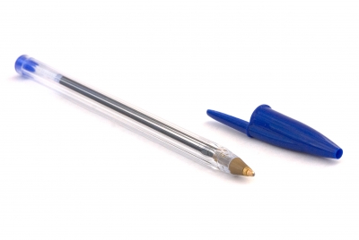
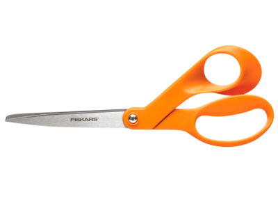
| Pen | Scissors |
|
|
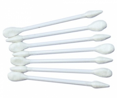
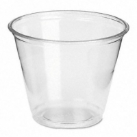
| Cotton Swabs (Q-Tips work fine) | Plastic Cup |

|
|
| Gloves | Disposable underlay |
|
|
|
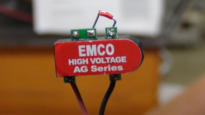
High Voltage Amplifier |
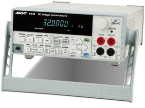
Voltage source (signal generator if possible) |
Pre-step: Make stencils and frame
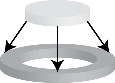
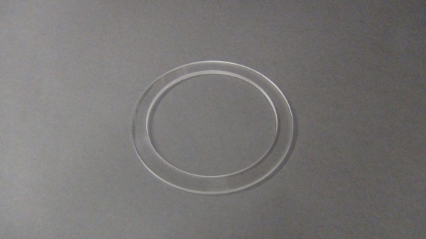
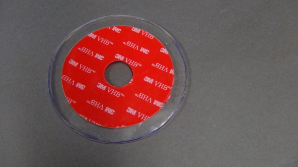
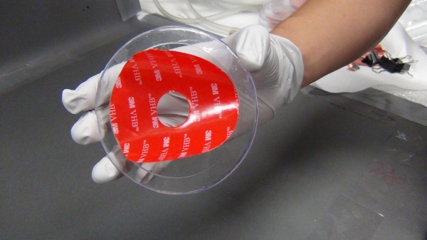
The circular actuator fabricated in this documentation uses an equibiaxial prestretch of 3 (i.e. the membrane is stretched three times equally in all directions). In order to achieve this prestretch, the acrylic frame and the initial piece of VHB must have the correct dimension ratio (3:1). The important dimensions to consider are the outside diameter of the acrylic frame and the outer diameter of the stencil used to cutout the initial piece of VHB.
We make the rigid frame out of acrylic so that it can be reused multiple times. The VHB can be simply peeled off and the frame washed in order to use it again. The two stencils are made using the red cover foil that is attached to VHB 4910 when it is sold from 3M, because it does not stick to VHB and therefore does not damage it upon removal.
 |
|
 |
|
 |
|
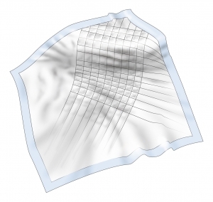
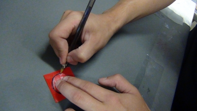
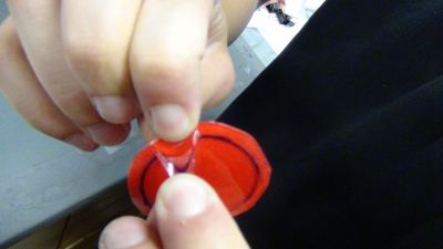
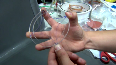
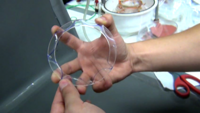
Step 1: Prestretching
Make sure to start with a clean working area. It is not necessary to have a perfectly clean actuator, but dust and debris can damage the membrane, leading to a failed actuator.
Do not use gloves for this step. The VHB sticks to the glove material and makes working with it difficult.
 |
|
 |
|
 |
 |
|
 |
|
|
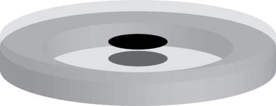
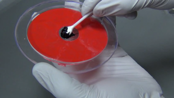
Step 2: Paint Active Area
Working with Carbon Grease
Carbon grease is a material that quickly contaminates the whole workspace including clothes and shoes. Always wear gloves as soon as carbon grease is applied to the membrane and use a disposable underlay. If you value the clothing you are wearing, immediately change a glove if it becomes dirty in order to avoid any further contamination.
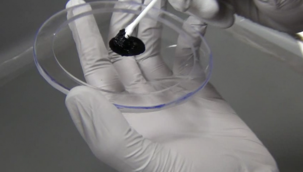
Before painting, put some of the carbon grease from the tube into a plastic cup for easier handling.
Painting the active area
 |
|
 |
|
|
|
 |
|
|
Save any leftover carbon grease and cotton swabs for step 4.
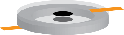
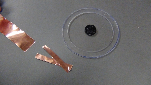
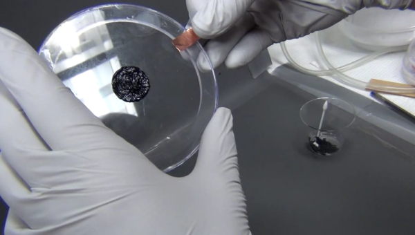
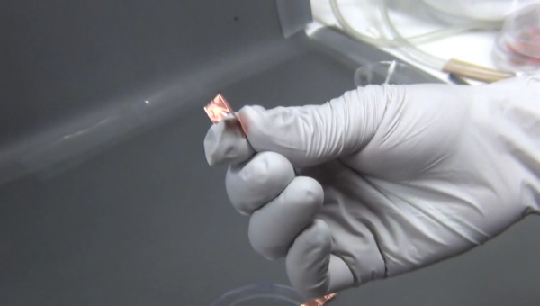
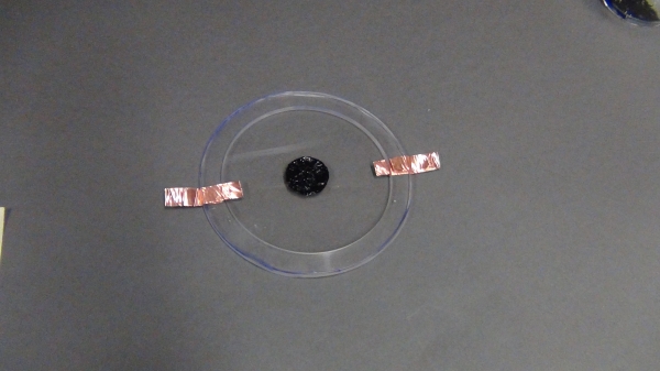
Step 3: Attach Copper Tape
In this step, short pieces of copper tape are attached on opposing sides of the active layer. The copper tape is folded over to allow attachment a high voltage amplifier later.
Fixing mistakes from Step 2
If some stray carbon grease found its way outside the active area during Step 2, simply choose that direction to attach the copper tape. Draw an imaginary line from the active area through the mistake and attach a strip of copper tape where that line intersects with the frame. A line of carbon grease will be painted right over the mistake in Step 4, covering it up.
 |
|
 |
|
 |
|
 |
|
|
|
 |
|
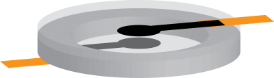
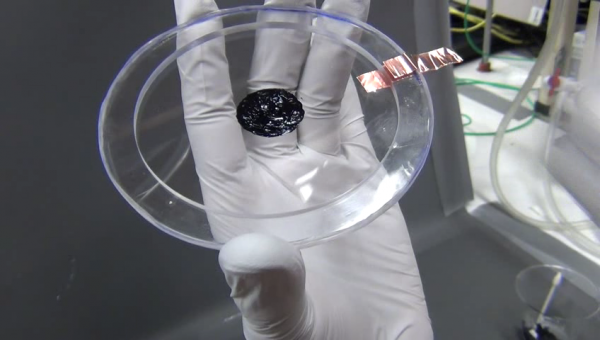
Step 4: Connect Active Areas to Leads
The last step involves connecting the active areas to the copper tape attached in the previous step.
|
|
|