Design
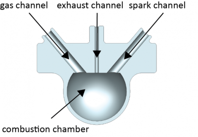
The combustion-driven actuator documented here consists of one single combustion chamber. This chamber has three channels to plug a gas injection nozzle, a spark gap (to trigger ignition) and an exhaust channel. This CDA is designed for demonstration purposes, so there is a horizontal cylinder that serves only as a handle to hold the soft actuator in position for testing. It can be seen in the picture below running perpendicular to the exhaust channel above the combustion chamber.
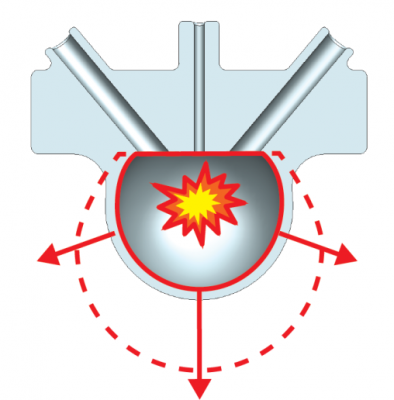
Upon a combustion event, the expansion will inflate the combustion chamber. Due to the chosen geometry of the CDA, the thin wall will stretch, while the thicker, horizontal section undergoes almost no movement (shown below). This repulsive motion can be extremely useful in robot design, where fast actuation plays a key point.
Combustions impose an incredible stress on the soft material. The first combustion driven soft robot presented by Shepherd et al. broke down after very few ignitions. One of the main reasons that robot failed was the use of two layers glued together to form the body. This revealed that a monoblock structure made from a single material is essential for combustion-driven actuators. This is why the main focus of this documentation is on the lost-wax mold design to produce these actuators.
The next two sections provide some background on material selecting criteria. Additionally we have a detailed tutorial on making the solid models of the actuator and the corresponding lost-wax-like mold using NX. The resulting part files as well as .stl files for 3D printing the lost-wax-like mold can be downloaded here. The part files include .stp formats for users of other CAD software, but we suggest following along with the tutorial in spirit and attempting to mimic the results in your own software.
Variation: Material
The material choice is much more important for combustion-driven actuators than for others. No company actually tests their silicones under simultaneous stress (i.e. thermal and mechanical). Therefore, silicone data sheets only tell half the story. However, we found several silicones that are able to withstand thermal and mechanical stress up to 30,000 combustion events. We'll start with some information about our selection criteria.
Selection Criteria
We use room temperature vulcanizing (RTV) silicones from Altropol GmbH*. They offer a wide range of two component silicone systems.
*Note: Like all of our guides, this was written by contributors from their own experience. Users in other countries may have to search for alternative suppliers.
The following points largely influenced our material selection:
- Handling Viscosity (HV) – Since we will later press the uncured silicone mixture inside our lost-wax-like molds, we need a mixture with a viscosity below 60 Pa·s (that of thick Maple Syrup). Otherwise, we need to apply larger pressures in order to fill the molds within the given handling time.
- Handling Time (HT) – The mold filling process takes, depending on the size of the mold, up to 80 minutes (for some silicones you will reach the handling time limit well before this). A rule of thumb from our experience: you need about 10-15 minutes per 100 cm3 including all preparation steps.
- Maximum Elongation at Break (MEB) – This value indicates if a material actually is able to withstand a combustion event. We suggest choosing a material with at least 500% MEB. Since thermal stress seems to decrease this value, a higher MEB would be preferred.
- Shore A Hardness (SA) – This value indicates weather a silicone is stiff (Shore A = 100) or very flexible (Shore A = 0) by measuring the depth of metallic cylinder being pushed into the surface with a force of 25 N. The higher the Shore A hardness the more violent the actuation.
Recommended Material Types
Condensation systems:
- RTV 1701 (HV = 22 Pas, HT = 80 min, MEB = 1000%, SA = 23)
Note: Condensation based systems will shrink with time. This is because the condensation product, a short alcohol, evaporates from the silicone.
Addition systems:
We achieved over 1,000 combustion events using the RTV 23 and over 30,000 for the RTV 1701. The exact handling of the presented silicone types is described in the fabrication section.
Lost-Wax Casting
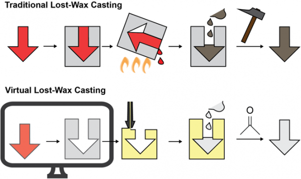
Lost-wax casting is a technique normally applied to cast metal. The process begins by producing a duplicate of the final part made from wax. This wax part is then placed in a box, which is filled with cement. After curing, the cement block is heated up and the wax melts and pours out. The remaining cement is now a negative of the final part. This negative mold is then filled with melted metal. After cooling, the cement mold is destroyed and removed, leaving a cast metal part.
Virtual lost-wax casting
Our fabrication process uses the same casting idea but uses other materials than metals. We virtually design a part and then create a virtual mold by inverting the part design (see Computer Aided Actuator Design). This mold is then 3D printed and filled with uncured silicone. After curing, we destroy the mold by dissolving it in solvent.
Computer Aided Actuator Design
We designed this actuator using the computer aided design (CAD) software Siemens NX. The following short tutorial shows how to design such a combustion driven actuator. Note that other CAD software (i.e. SolidWorks, Inventor, AutoCAD,…) can be used, but this tutorial is specifically for NX software. The main reason to use NX is its simplicity in creating free forms. This might be helpful especially if you want to design complex geometries. If you do not have access to NX, we encourage you to follow along through the guide to understand the design process in principle and even to attempt to replicate our design in your own software of choice. Downloads of the part files for the actuator design in this tutorial can be found here which include formats compatible with most CAD software.
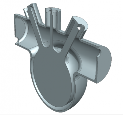
In the following sections, we show you how to create the simple combustion driven actuator shown below. All necessary sizes are indicated in the figure below. The design is comprised of a cylinder, which partially drives through a hollow sphere. Three channels, aligned at different angles towards the sphere center, form the gas inlet, exhaust and igniter electrode connection.
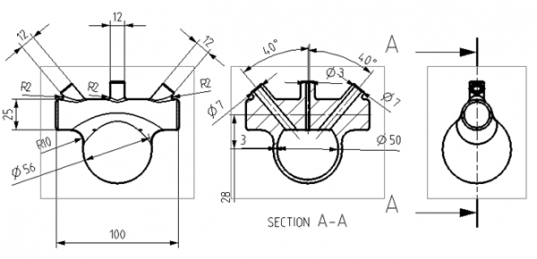
Again, all part files can be found here.
Step 1: Rough Design
Begin creating the part
- Start by creating a new model file in NX. (File → New: Choose Model/Modelling).
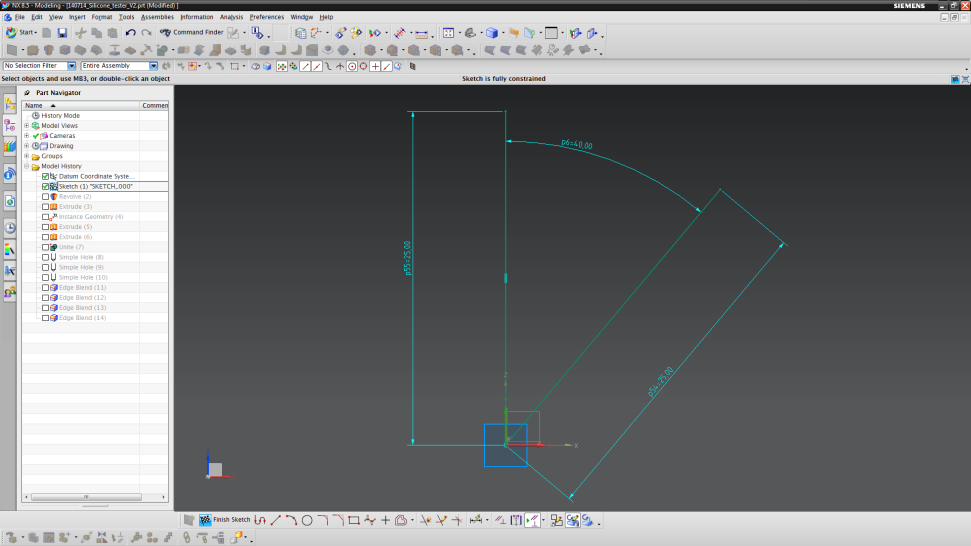
- Then, make a new sketch drawn in the XZ-plane (Insert → New Sketch: choose XZ-plane with your mouse).
- Draw two lines 25 mm in length, starting at the origin. The angle between the lines should be 40°. These lines will help to align the channels in later steps.
- Lastly, click on “Finish Sketch” located in the bottom toolbar.
Design the combustion chamber.
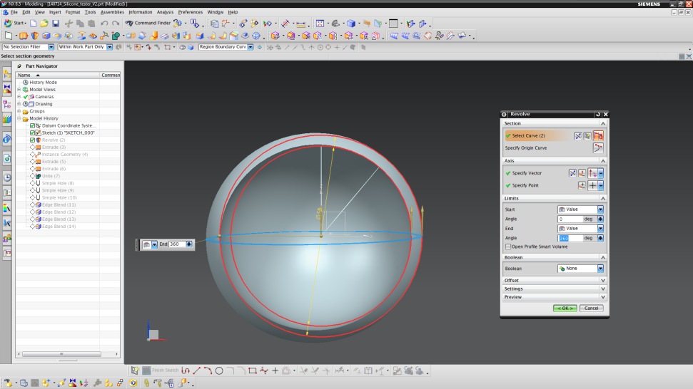
- Insert a revolved part (Insert → Design Feature → Revolve).
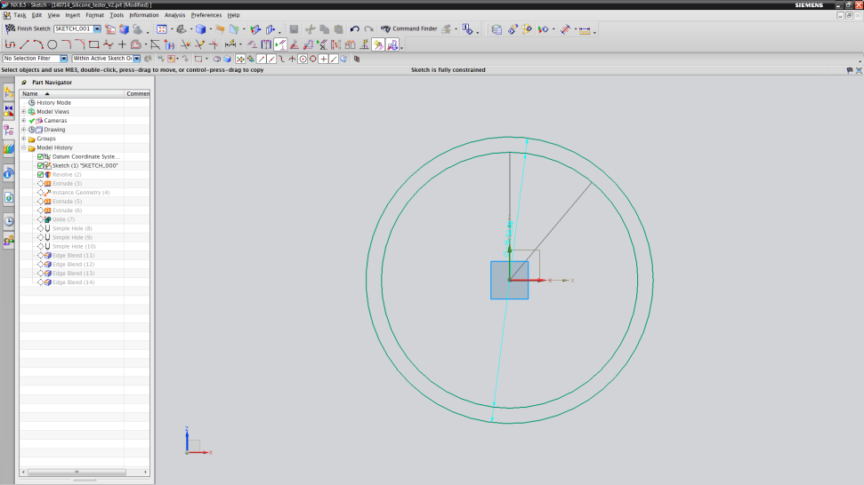
- Click on the “Sketch Selection” item in the new “Revolve” menu. A new sketch should appear. Choose the XZ-plane again.
- Now sketch two circles (Insert → Curve → Circle) with origin (0,0) and diameters of 50 mm and 56 mm, respectively.
- To go back to the "Revolve" menu, click on "Finish Sketch" again (the button is in the upper left corner now).
- Then choose the vector to be the Z-vector (should be blue) and the point to be the point of origin.
- The angle should start from 0° until an angle of 360°.
- Finalize by clicking on OK.
Add channels
- Hide the hollow sphere by right-clicking on the “Revolve (2)” item in the part navigator (left panel). Choose “Hide” and the sphere is now hidden.
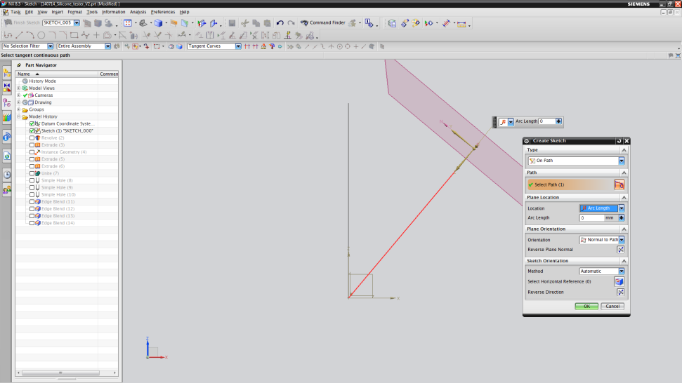
- Insert an “Extrude” part (Insert → Design Feature → Extrude).
- Click on “Sketch Selection” item in the “Extrude” menu. A new window (“Create Sketch”) will open. In the type section, choose "On Path".
- Then choose the sketch-line at 40° drawn before. Set "Arc Length" to 0 mm and click "OK". The view will now turn.
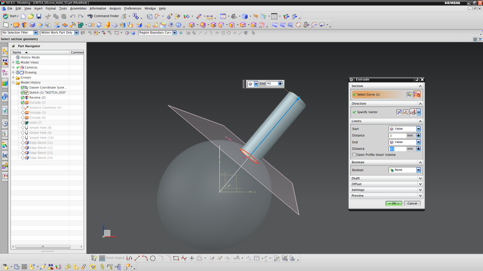
- Draw another circle with origin (0,0) and a diameter of 12 mm.
- Click on “Finish Sketch” after you are done.
- Choose a specific vector. In our case, it is the "Face/Plane Normal".
- Set start and end distance to 0 and 40 mm, respectively.
- Finalize by clicking "OK".
- To create the middle channel, repeat the steps used to create the first channel.
- This time, choose the guide line perpendicular to the sphere.
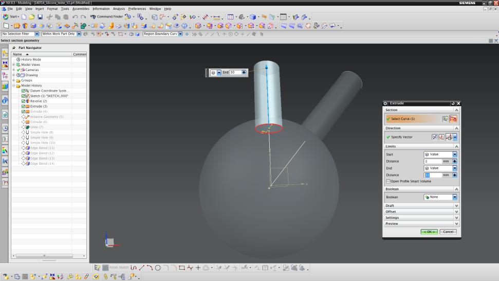
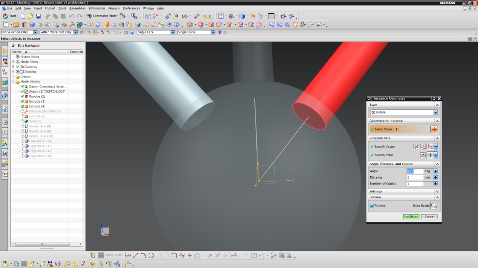
- To make the left channel, we can just create a mirrored copy of the right channel.
- Copy the geometry (Insert → Associate Copy → Instance Geometry).
- Click on Select Object and then choose the cylinder at 40°.
- Specify the vector to be the Z vector (vertical axis) and the point to be the point of origin.
- Set the "Angle" to 180° and the "Number of Copies" to 1.
- Finalize by clicking on "OK".
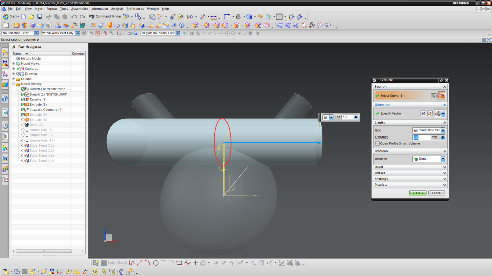
Add horizontal cylinder
- Add another "Extrude"-part.
- Choose the ZY-plane for the sketch.
- Now sketch a circle with an origin of (0,28) and a diameter of 25 mm.
- Finish the sketch to return to the "Extrude" menu again.
- In the "Limit" section choose "Symmetric Value" and enter 50 mm.
- Finalize by clicking “OK” again.
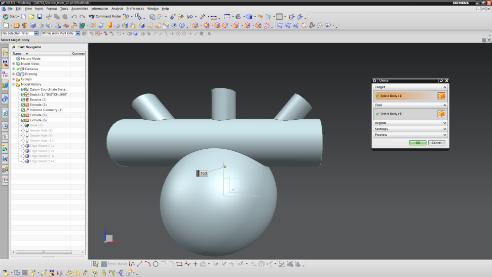
Unite
- Unite all parts (Insert → Combine → Unite).
- Select all parts and finalize by clicking "OK".
Step 2: Holes & Blends
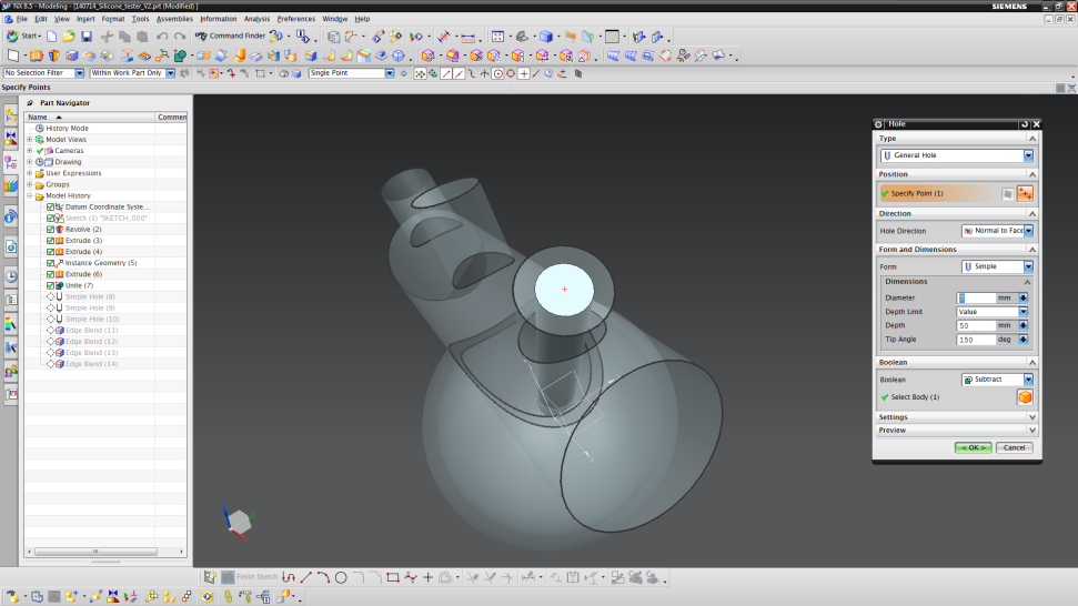
Add channel holes
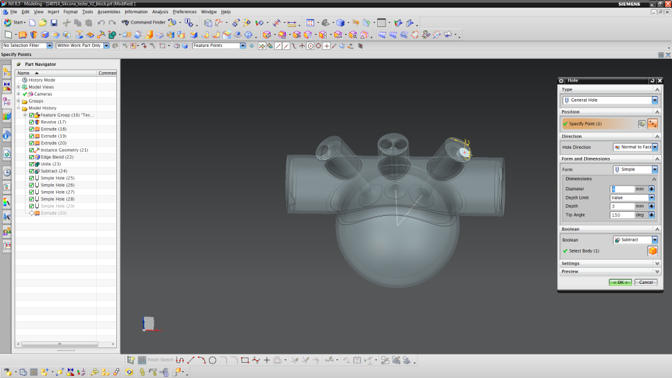
- Now, we build the holes into the cylinders to get our channels (Insert → Design Feature → Hole).
- Zoom in on one channel as shown in the image below and choose the edge of the extruded cylinder.
- The edge should be highlighted in yellow.

- Now enter the data for the channel.
- Set the “Diameter” to 7mm, the “Depth” to 50 mm and the “Tip Angle” to 150°.
- Finalize by clicking “OK”.
- Repeat this process for the left channel.
- The middle channel uses the same procedure, but with a diameter of 3 mm.
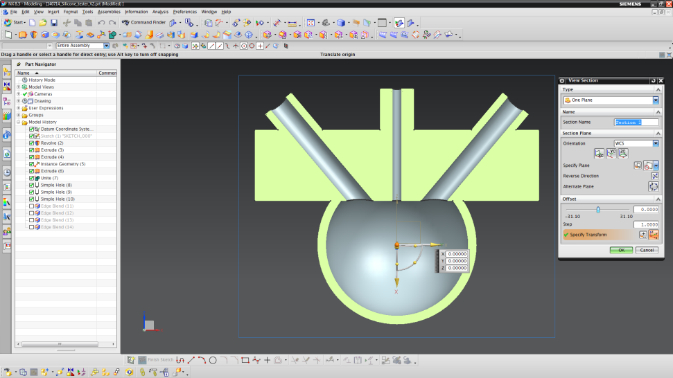
- To check whether your channels penetrate into the combustion chamber or not, use “Crtl+H” to open the “View Section”.
- Choose the YC-orientation and click “OK”.
- Now, your actuator should look like the figure below. If so, exit the “View Section” (View → Section → Clip Work Section)
Add edge blends
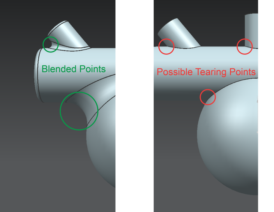
- Now, we add edge blends in order to smooth the surface.
- This is important, since the silicone has a higher chance to tear where there is an incisive angle.
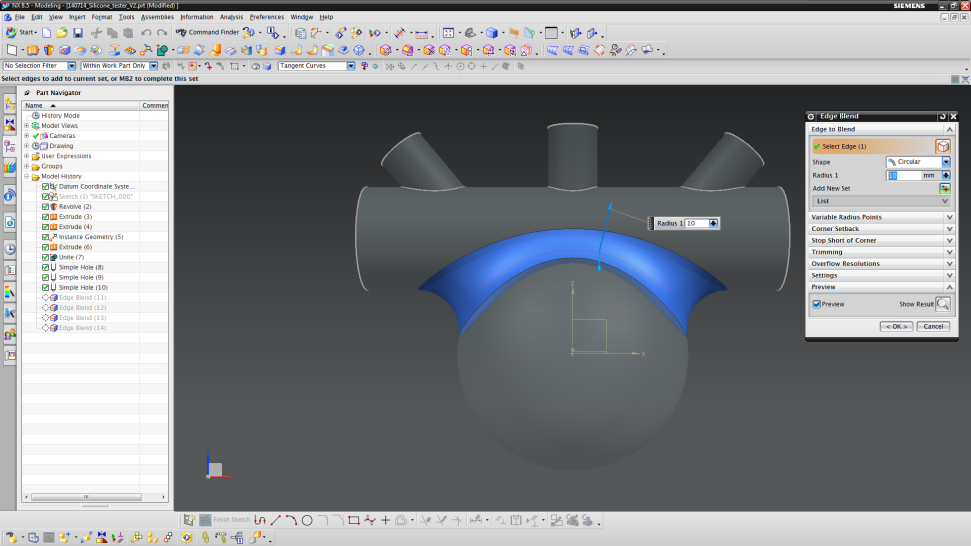
- Insert a blend (Insert → Detail Feature → Edge Blend).
- Choose edge separating the horizontal cylinder from the combustion chamber.
- Choose a radius of 10 mm.
- Finalize by clicking “OK”.
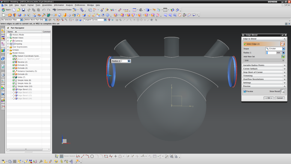
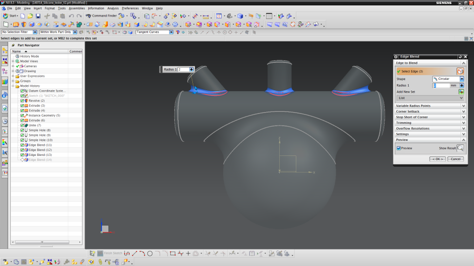
- Select the two edges shown below and use a radius of 2 mm.
- Select the edges shown below and use a radius of 1 mm.
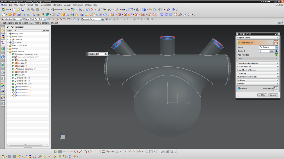
- The edges shown below should also have a radius of 2 mm.
- Finalize again by clicking “OK”. You now have designed your combustion driven actuator.
Step 3: Mold Design
Designing the mold
Now that the actuator has been designed, we need to make the mold that will allow us to cast the part. To do this, we will "invert" the design from the previous steps. This inversion process essentially involves making a part that has the same shape, but with slightly larger dimensions in order to enclose the actuator design and then subtracting the actuator design to create a hollow mold. We then have to add filling and venting holes to allow silicone to enter and air to escape the mold during casting. This section will detail how to create the basic mold for the actuator designed in those previous steps.
Note: The minimum wall thickness of the mold should be 1.5 mm. Otherwise, your 3D printer might not be able to successfully print the mold. Also, the silicone filling becomes quiet difficult in terms of leaking spots.
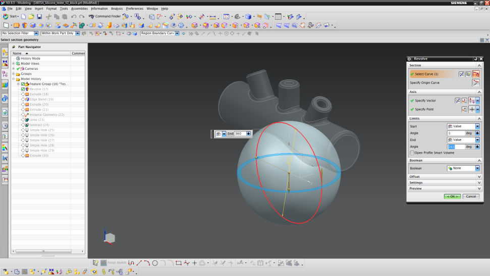
- Start by inserting a “Revolved” part (Insert → Design Feature → Revolve).
- Choose the ZX plane to draw the sketch.
- Sketch a circle with origin (0,0) and a diameter of 59 mm.
- Set the limits from 0° (start) to 360° (end).
- Next, add another “Extruded” part (Insert → Design Feature → Extrude).
- Choose the ZY-plane for your sketch and sketch a circle with origin (0,28) and a diameter of 28 mm.
- Unite the two parts by selecting the “Boolean”-setting to “Unite”.
- Like in Step 1, we now build the mold parts for the channels.
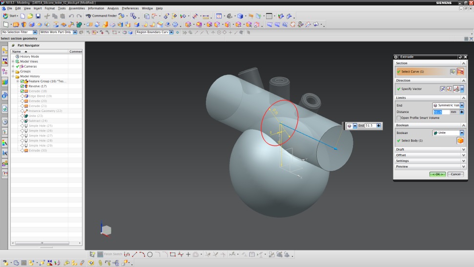
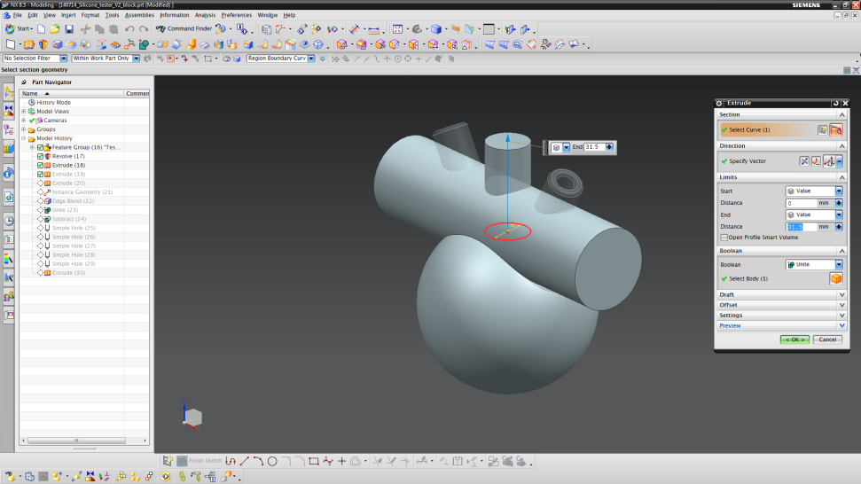
- Create an “Extruded”-part (Insert → Design Feature → Extrude) and set the sketch plane to the vertical orientation line (the sketch plane should face vertically) and draw a circle (origin (0,0), diameter 15 mm).
- Extrude the circle from 0 to 31.5 mm along the Z-axis.
- Unite the cylinder with the remaining parts by choosing “Unite” in the Boolean part.
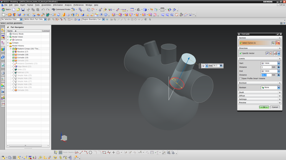
- For the sloped channels, extrude (Insert → Design Feature → Extrude) a cylinder from a circle sketched at origin (0,0) and a length of 36.5 mm along the sloped orientation line.
- Do not unite the cylinder with the remaining parts in the Boolean setting this time.
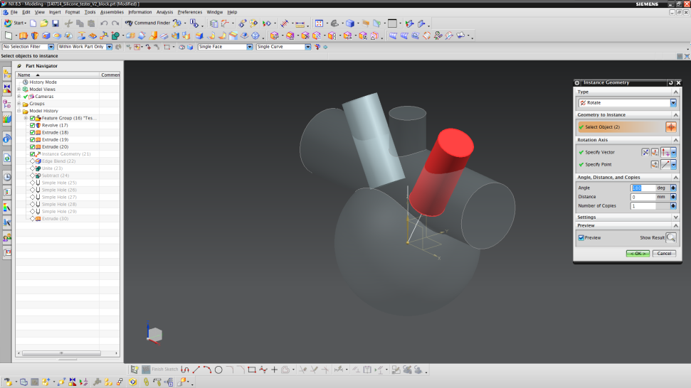
- Copy the cylinder as described in Step 1 (Angle = 180°, Number of Copies = 1).
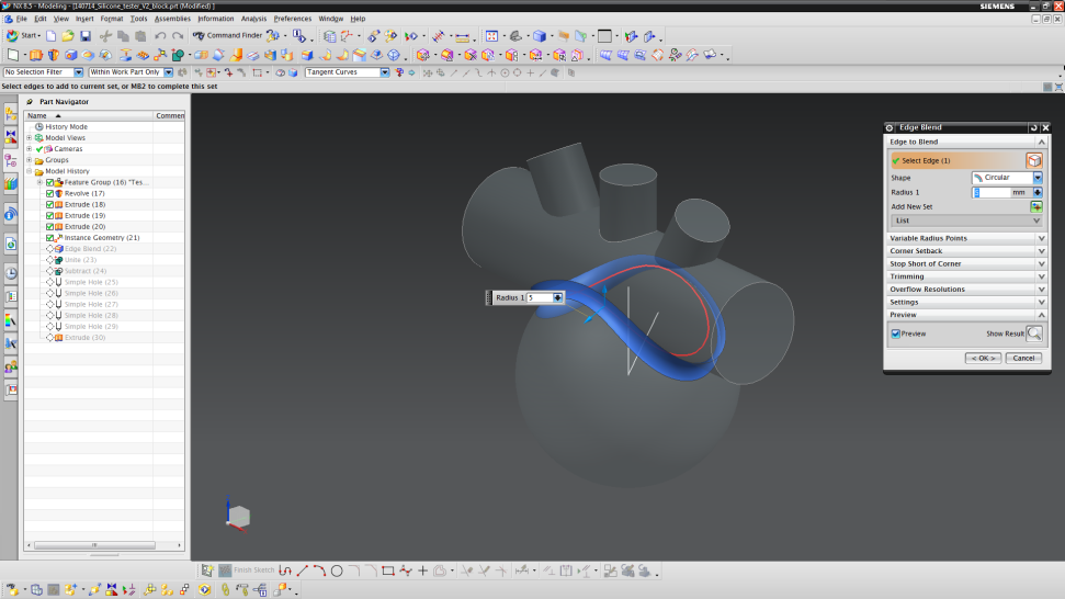
- Blend the connection of the sphere and horizontal cylinder as shown below. Choose an edge blend radius of 5 mm.
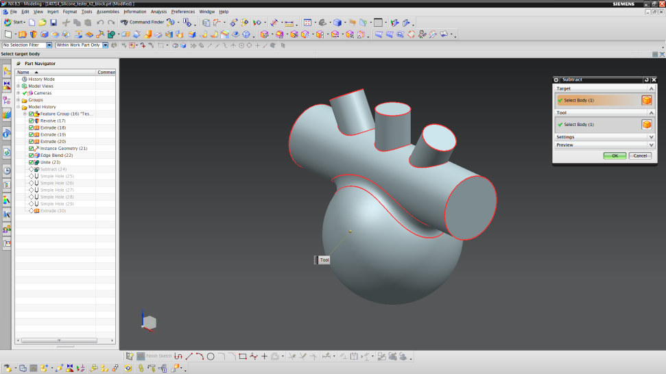
- Unite all mold parts designed in Step 3 using the “Unite” tool (do not include the actuator design from steps 1 and 2).
- Afterwards, subtract the actuator design from the mold to get the inverted design (Insert → Combine → Subtract).
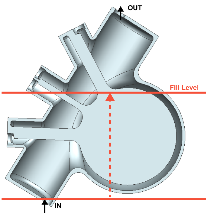
Dead volumes
One of the main problems when creating and filling a mold are dead volumes. These dead volumes can trap air and therefore destroy your design upon filling uncured silicone. Hence, the design not only has to be “inverted” to form the mold but also specific connections (in the form of vented holes) to the outside have to be made. The vented holes enable the escape of air, in order to allow silicone to fill the pockets that would otherwise be filled with this trapped air. Our design needs four of these vents, which are all positioned at the end of a channel inlet.
Add all necessary filling and vented holes by adding holes into the hollow mold
- We first make the holes that will be used to fill the mold with uncured silicone.
- Begin the process by inserting a hole (Insert → Design Feature → Hole).
- The first hole is set on one of the faces of the horizontal cylinder.
- The center of the hole should have coordinates of XC = 0 mm and YC = 18 mm.
- Specify a diameter of 6 mm, depth of 3 mm and a tip angle of 150°.
- The next hole will be on the opposite face of the horizontal cylinder.
- This time, the hole should be at XC = 0 mm and YC = 37 mm.
- Use the same hole dimensions as before.
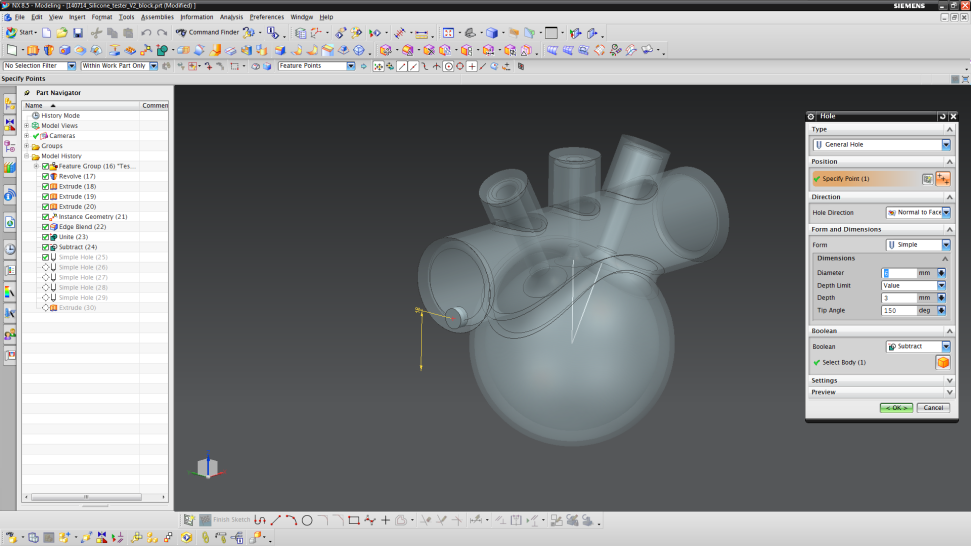
- Now, we will make the vented holes.
- Insert another hole and choose to sketch on one channel top.
- The point should be at XC = -3.5 mm and YC = 0 mm.
- Use the same hole dimensions as for the horizontal cylinder.

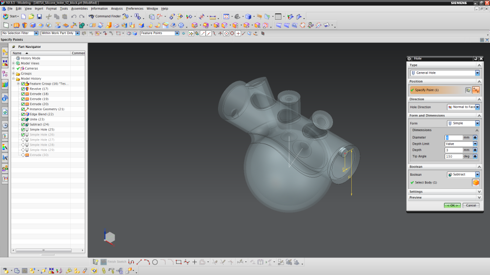
- For the vertical channel, we will make two holes.
- Insert another hole and choose to sketch on the top face of the middle channel.
- The two points have to be on the same horizontal line (XC1 = -3.5 mm / YC1 = 0 mm and XC2 = 3.5 mm / YC2 = 0 mm).
- Use the same dimensions as before.
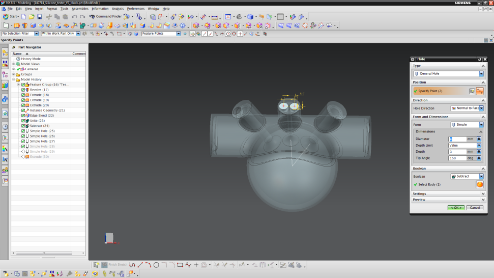
- The last hole should be designed on the remaining channel top surface at the point XC = 3.5 and YC = 0 mm. Continue to use the same dimensions for the hole.
- Now, your mold should have an interior as shown in the beginning of Step 3.
- To see the cross section, press “Crtl + H” and choose the YC plane.