Fabrication
This section contains a detailed description of the fabrication process to manufacture combustion-driven actuators (CDA). One of the key features to produce lost-wax casted soft silicone actuators is 3D printing. We therefore explain in more details the principle behind this technique, the importance of the printed polymers and highlight the resulting advantages. We additionally explain the casting and mold removal processes. A detailed Bill of Materials listing all parts and materials needed to fabricate the combustion-driven actuator shown in this documentation can be downloaded here.
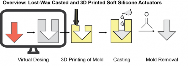
Process Overview
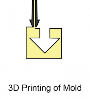
| 3D Printing the Mold: After the mold design (see Computer Aided Design section) is established, the data gets processed and loaded into 3D printing software. This software then produces an operation chart, enabling the 3D printer to print the mold. |  |
| Casting: After post-treatment of the 3D printed mold (more details are given in the relevant subsection), a mixture of uncured silicone and its necessary crosslinking agent is pressed inside the voids to cast the mold. | 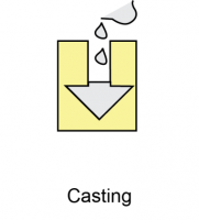 |
| Mold Removal: The mold around the cured actuator is then removed by dissolving the mold polymer in a solvent. This process frees the final actuator and produces the previously mentioned and very important monoblock structure. | 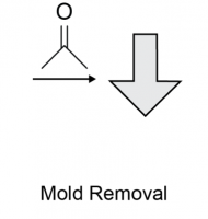 |
3D Printing the Mold
 3D printers belong to the class of fused deposition modelling (FDM) devices. They build parts layer-by-layer by melting model or support polymer wire inside a hot fuse which is then extruded onto a platform and cured on the fly. Our system uses acrylonitrile-butadiene-styrene (ABS) co-polymer for the model and polylactic acid (PLA) as support material, but similar systems with different materials will work just as well to make the mold. The only caveat is that the model material must be dissolvable in order to remove the cast actuator once it is set. More details are given in the Mold Removal section.
The printer software calculates the tool path from a triangulated surface file of the CAD model (usually an .STL file). The 3D printer cannot print material on air, so support structures are used to build a printing platform and to fill any voids. The model material layers then build the actual part on top of the support material. The support structures can now be removed, leaving only the model behind. We used the following printers to make this actuator mold:
CAD File conversion
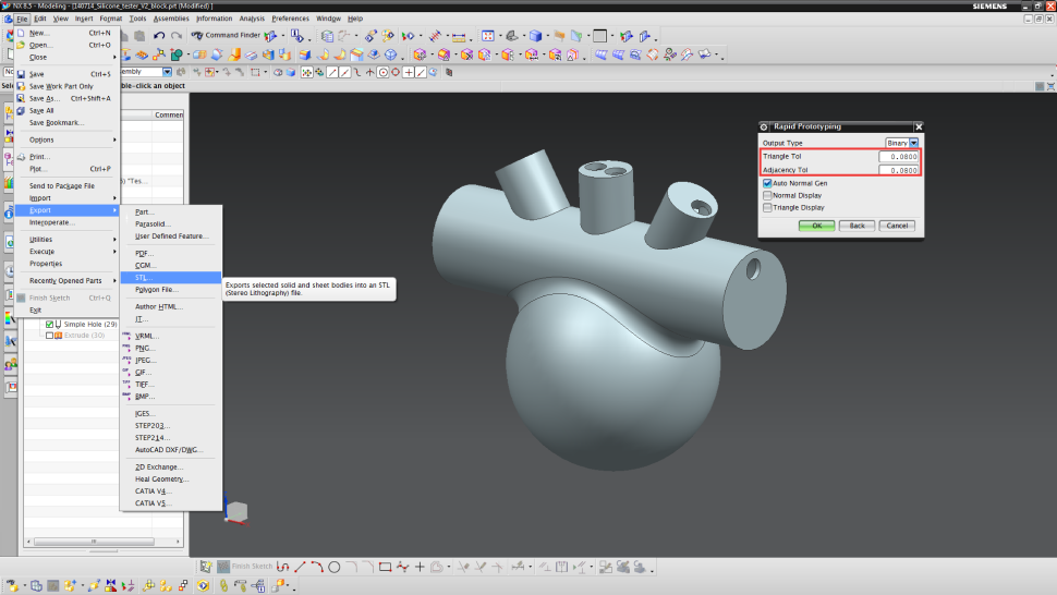
First, the CAD part-file has to be exported into .stl (File → Export → STL). This file format delivers the necessary triangulation for the 3D printing software. In the red square, important exportation parameters are highlighted. The lower this value is, the larger the file size will be, but also the better the input resolution of the mold. We suggest to use a triangle resolution and an adjacency tolerance of 10-3 at least.
Set-up 3D Printer
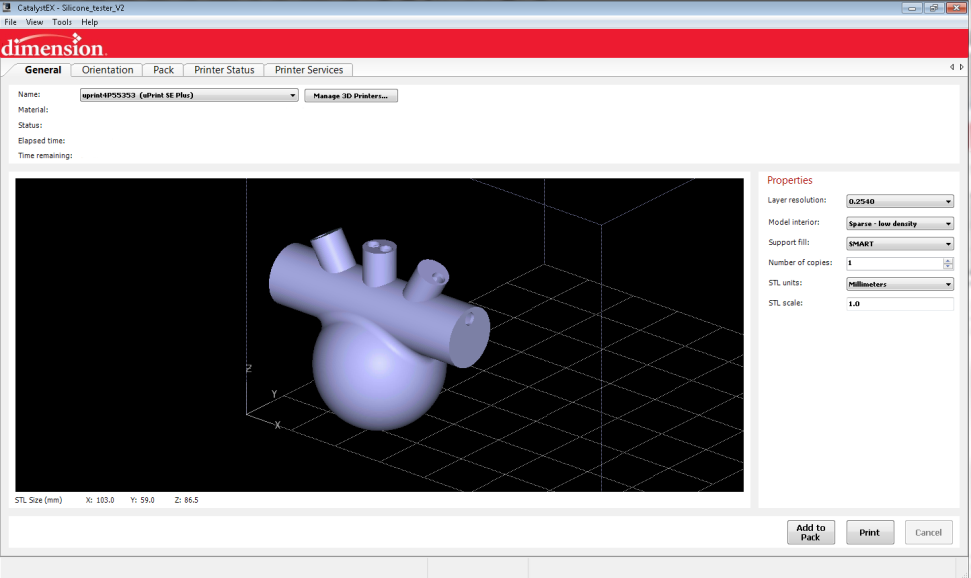
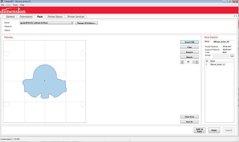
The .stl-file now can be loaded into the 3D printing software (File → Open STL). Choose the layer resolution to be 0.254 mm and set the model interior to “Sparse – Low density”. We want the mold to be easily dissolvable in later steps, so having a low density will allow solvent to penetrate the mold easier. Then, click on the “Orientation”-tab (upper left).
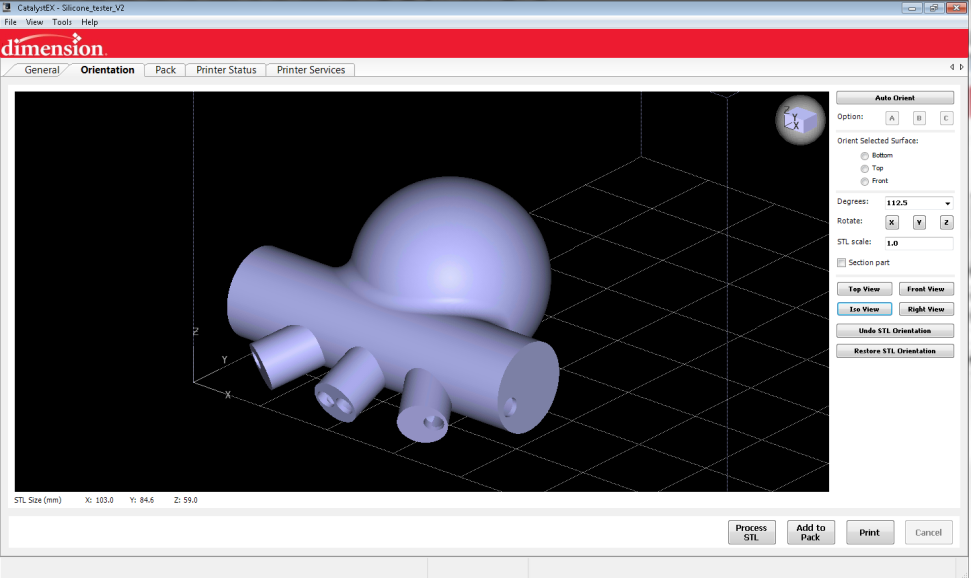
Depending on the positioning of the model part, more or less support material is needed. Therefore, the part needs to be turned to minimize the material need. Turn the part by entering 112.5 degrees into the corresponding field and click on “Rotation:X”. The part now turns. Then click on “Add to Pack”. The software will now calculates all tool paths.
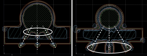
All tool paths are shown (red for material, purple for support tool path) after the completion of the calculations. Now, verification is needed. The mold has an inner sphere (representing the combustion chamber), which is connected to the three cylinders (representing the channels). There has to be a connection to the outer mold shell, otherwise the interior geometry is not set in place correctly (loose parts inside). To verify this, click on “Top View” to change perspective and choose the displayed layer to be “Top”.
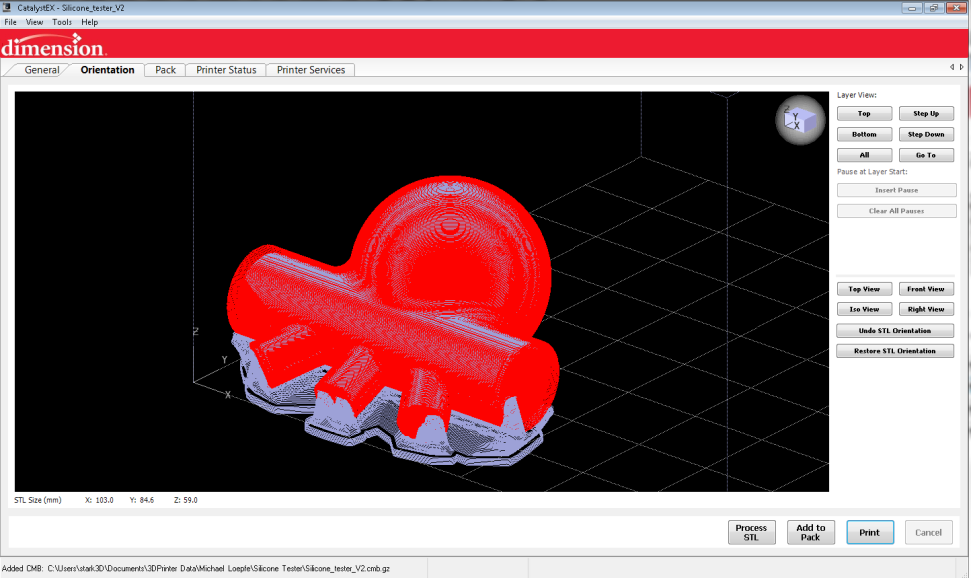
By pressing “Page Up” or “Page Down” on the keyboard, one can switch within the layers. Go down. You will reach a layer where suddenly, the spherical combustion chamber has three extruded fingers (left picture). As you continue down the layers, these fingers move along the dashed lines until they reach the outer mold shell (right picture). Thus, this design has a connection between the inner geometry and the outer shell.
Next click on the tab labeled "Pack" (upper left). Here, the positioning of the parts can be performed. This is especially interesting, if you would like to print the actuator mold several times. On the right side, details on your model and support material consumption, as well as the estimated printing time are given. Click “Print” to start. Then follow the instructions given on your 3D printer.
The Printing Process
The printing process is very reliable and robust. Nevertheless, a few things you should remember when using these 3D printers:
- Platforms can be used several times. After a while, adhesion of the first layer is reduced and a part can peel off (creates a huge mess inside your printer and may damage your fuse head). Therefore it is advisable to use new platforms for large molds.
- Calibrate X,Y and Z-axis periodically. This helps to give you stable printing performance. Also check whether your fuse has any polymer deposits nearby. These might interfere with any freshly printed layers.
- Humidity affects your printing. Therefore store everything in a dry environment. Unload all materials, especially if you do not print for several weeks.
Mold Post-Treatment
The mold has to be washed in an alkaline bath to remove the support structure (base catalyzed degradation of PLA). This process can be sped up by heating to 60°C and introducing convection by a circulation pump. Also, specific flushing of the mold helps to dissolve the PLA. Once the support material is dissolved and washed away, the CDA mold is then dried and can be prepared for the casting process.
In principle, any model/support system can be used to print molds. The important step is the mold dissolution. If a solvent does not dissolve the model material, the casting technique does not work. More details are given in the section: Mold Removal.
Casting
 The casting process to build a combustion-driven actuator (CDA) with a necessary monoblock structure consists of three steps. First, the mold has to be prepared by connecting casting parts. Then, the silicone has to be mixed. Last, this mixture is injected into the mold and cured. Even though these steps seem to be simple, we will show a few tricks to increase your casting efficiency. Some of the preparation steps are also illustrated in the video below.
Mold Preparation
The mold we've created needs a few additional parts prior to casting. These parts will further help to prevent any dead zones, which would trap air (other preventive steps are explained in Step 3 – Mold Design).
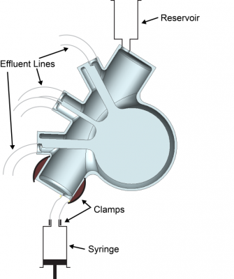
- First, the mold has to be fixated using a clamp. The orientation of the mold needs to be in such a way that air can easily escape trough the vented holes we created earlier or through the reservoir.
- Then, tubing is glued onto each of the vented holes. We use silicone tubing and hot glue for this step.
- A reservoir for uncured silicone is installed on top. Since uncured silicone is likely to diffuse into the porous first mold layer as the actuator cures, this material pool helps to keep the mold filled until complete curing. This can be made of an empty syringe, glued on top.
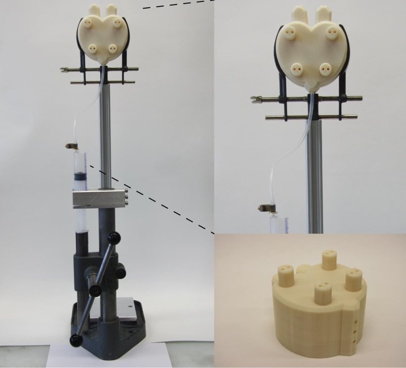
- Last, the injection line has to be installed. We again use silicone tubing for this step. Silicone is later filled into syringes and injected by an in-house made hand press (a picture of this press is shown further down this page). One syringe cannot hold all of the silicone needed to fill the mold. Therefore, a fast connector is needed to exchange empty syringes with full ones. This connector is made of a metallic hull inserted into the tube and then tightened with a clamp. (See video below for details).
Silicone Mixing
Mix silicone according to the instructions given by your manufacturer, in our case Altropol (usually given at the end of each data sheet). Each system has its own monomer to cross linker ratio. Mix until a homogeneous material is obtained, either by hand or with a mixer. We also suggest you degas the mixture to decrease the amount of dissolved air. This helps to avoid entrapped air in the molds.
Injection
The figure below shows the previously mentioned silicone press (taken from Schumacher et al.). The syringes (50 mL) are filled with the uncured silicone mixture and then injected into the mold until the reservoir is full. When a tube connected to a vented hole starts to fill with silicone, a possible dead zone has been completely filled with silicone and that escape route is no longer needed. You can inject hot glue into the tubing to seal it so no more silicone escapes. (This technique is shown in the video below).
A few tricks:
- Do not put too much force on the press. This creates pressure peaks and the injection line may burst or the syringe can break down.
- Heat-shrink tubing can support silicone tubing in critical flow regions (i.e. at the injection site)
Mold Removal
 Once we have the mold with fully casted and cured silicone, we need to remove the mold. Unfortunately, because of the monoblock structure of the actuator, we cannot simply open the mold and release the actuator. We must destroy the mold and the most effective method is to choose a mold material that is strong enough to hold up to the molding process, but is also soluble in certain liquids. We have chosen ABS because it is soluble in acetone, so we can simply dissolve it away.
- Put the molds containing cured silicone into a bath of acetone.
- After a while, the dissolving process has advanced in such a way that one can peel off the outer shell. The inner ABS structures will need more time.
- One can accelerate the dissolving by slightly pulling away the silicone wall from the structure, with a spatula for example. Then, the gap created between the ABS and silicone can be filled with acetone. Another possibility is to inject acetone directly into the inner mold.
- Due to the low density printing, there should be enough voids to fill. If enough acetone has entered the mold material, the dissolving will take much less time.