Finite Element Modeling
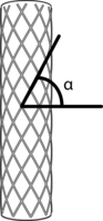
This section describes a Finite Element Method (FEM) model for a particular type of fiber-reinforced actuator using the Abaqus software suite. This actuator differs from the fiber-reinforced actuators discussed in the rest of the documentation, as it consists of a cylindrical elastomeric tube, with circular cross section, and with fibers wrapped in a helical pattern around the outside of the tube. The fibers constrain the motion of the actuator, as they have a much higher stiffness than the elastomer. The angle between the fibers and the horizontal is referred to as the fiber angle α.
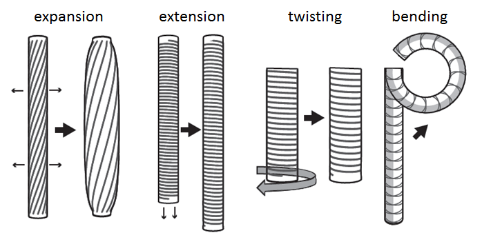
When pressurized, this type of actuator is capable of four types of motion: radial expansion, axial extension, twisting about its axis, or bending. When the elastomeric tube is of uniform stiffness, some combination of expansion, extension, and twisting occurs upon pressurization. When the elastomeric tube is made of two different materials (with different stiffnesses), pressurization produces a bending motion.
The effect of the fiber angle on the behavior of extending, expanding, twisting actuators is illustrated in the video below.
This tutorial describes the procedure for creating an Abaqus model of a fiber-reinforced actuator which extends, expands, or twists upon pressurization. The Abaqus cae file created in this tutorial can be downloaded here: FR_tutorial.cae. To create a model of a bending actuator, follow the main tutorial, and take note of the alternative steps in italics, which describe the modifications which need to be made to produce a bending actuator.
Overview of model components
- A Fluid-Structure Interaction (FSI) problem treated with a standard/implicit FEM using Abaqus/CAE (SIMULIA, Dassault Systèmes)
- Materials:
- Elastosil M4601 silicone rubber: neo-Hookean strain energy potential defined by the coefficient C10 = 0.12MPa.
- Kevlar fiber: elastic material with Young’s modulus 31067MPa and Poisson’s ratio 0.36.
- For a bending actuator:
- Dragon Skin 10 silicone rubber: neo-Hookean strain energy potential defined by the coefficient C10 = 0.0425MPa.
- Smooth-Sil 950 silicone rubber: neo-Hookean strain energy potential defined by the coefficient C10 = 0.34MPa.
- Kevlar fiber: elastic material with Young’s modulus 31067MPa and Poisson’s ratio 0.36.
- Sections:
- Elastosil (uniform solid), assigned to the main body and caps
- Kevlar assigned to the fibers
- For a bending actuator:
- Smooth-Sil 950 (uniform solid), assigned to half of the main body and to the caps
- Dragon Skin 10 (uniform solid), assigned to half of the main body
- Kevlar assigned to the fibers
- 1 load:
- Pressure, acting at all internal faces of the actuator cavity
- Tie constraints between the fibers and the outer wall of the actuator
Overview of FEM steps
- Create parts
- Elastomeric tube and caps
- Fibers
- Create and assign materials
- Create surfaces and loads
- Create surface for applying pressure
- Create step
- Define boundary conditions
- Apply load
- Mesh the parts
- Add tie constraint
- Run job and view results
Scripting in Abaqus
More advanced users of Abaqus may note that all of the above can be done using the scripting interface. For a useful introduction to the Abaqus scripting interface see learnabaqusscriptinonehour.pdf. The scripts corresponding to the model developed in this tutorial can be downloaded here: FR_ACTUATOR.py and PARAMETERS.py. To run the script (equivalent to creating the model and running the job), go to File-> Run script, and browse to the file FR_ACTUATOR.py.
Acknowledgements and References
The content of this tutorial is based on the following work:
- F. Connolly, P. Polygerinos, C. J. Walsh, and K. Bertoldi. “Mechanical programming of soft actuators by varying fiber angle” Soft Robotics, 2015 vol 2 pp 26-32.
Many research groups have worked on this type of actuator, and further interesting references include:
- G Krishnan, J Bishop-Moser, C Kim, and S Kota, "Kinematics of a generalized class of pneumatic artificial muscles", J Mech Robot 2015 doi:10.1115/1.4029705
- S Hirai, P Cusin, H Tanigawa, T Masui, S Konishi and S Kawamura, "Qualitative synthesis of deformable cylindrical actuators through constraint topology" IROS 2000 pp. 197-202
- K Suzumori, S Iikura, and H Tanaka, "Flexible microactuator for miniature robots", Proceedings of Micro Electro Mechanical Systems 1991 pp. 204-209
| learnabaqusscriptinonehour.pdf | 257 KB | |
| fr_scripts.zip | 14 KB | |
| fr_tutorial.zip | 986 KB |
Step 1a: Create Parts
In this step, we will create the elastomeric tube and fibers that make up the actuator. Make sure to download the file fibers.py, as we will use that to create the fibers later.
For a bending actuator, download the file fibers_bending.py.
Create tube
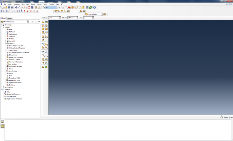
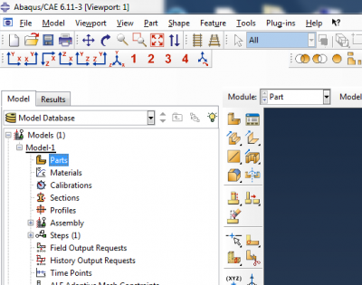
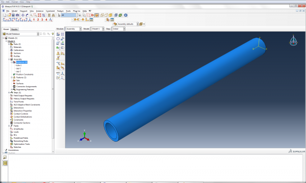
To begin, open a new project in Abaqus CAE. You should see a screen like below:
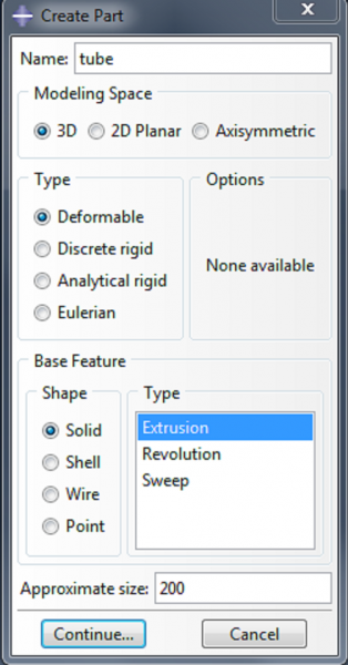
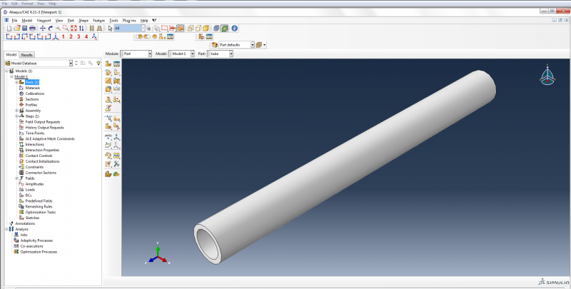
We form the main body of the actuator by creating a tube and then capping it at each end. To make the tube, double click on Parts. Name the part ‘tube’ and make it a 3d deformable solid extrusion.
  |
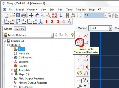
Now sketch the cross section of the tube. Click on Create Circle: Center and Perimeter.
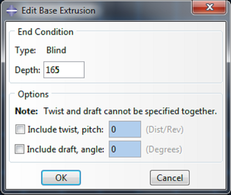 | Enter (0,0) as the center of the circle, and enter (6.35,0) as the perimeter point. Make a second circle with (0,0) as the center of the circle, and (8.35,0) as the perimeter point. Click cancel procedure and done. Enter 165 as the depth, and click OK. |
This gives us a tube with inner diameter 6.35mm, outer diameter 8.35mm, and length 165mm.
Create Caps
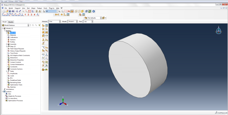
Next, create the geometry for the caps.
- Double click on Parts again.
- Name the part ‘cap’ and make it a 3d deformable solid extrusion like the tube.
- Click on Create Circle: Center and Perimeter.
- Enter (0,0) as the center of the circle and (6.35,0) as the perimeter point.
- Click cancel procedure and done.
- Enter 5 as the depth, and click OK.
Add parts to assembly
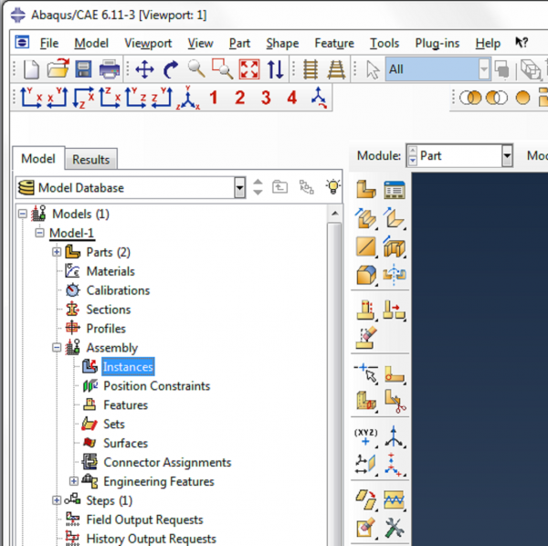
Now we need to merge the tube and the caps to make one part. To do this, we first need to add instances of each part to the assembly. Expand the assembly tree and double click on Instances.
 |
|
| Both of the caps are now positioned at the same end of the actuator, so we need to translate one of them to position it at the other end. In the main toolbar, click on Instance->Translate. |
Click on Instances in the bottom right corner of the screen.
Select ‘cap-2’ and click OK in the instance selection box.
![]()
Enter (0,0,0) as the start point for the translation vector and hit enter. Enter (0,0,160) as the end point, hit enter and then click OK to confirm the position of the instance.
Now there is a cap positioned at each end of the actuator.
Merge parts
To merge the caps and the tube, go to Instance->Merge/Cut.
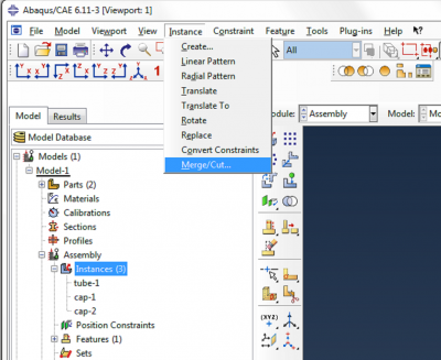
Name the new part ‘Merged_Actuator’, select Original Instances: Delete, and click Continue.
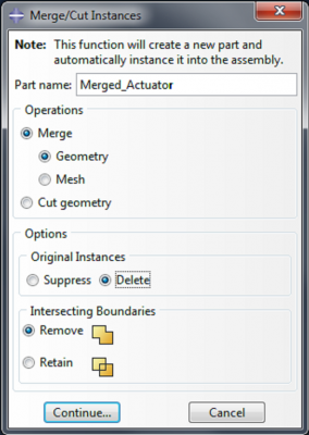
When prompted to choose which instances to merge, click on Instances in the bottom right corner. Hold the ctrl key, select the three instances and click OK.
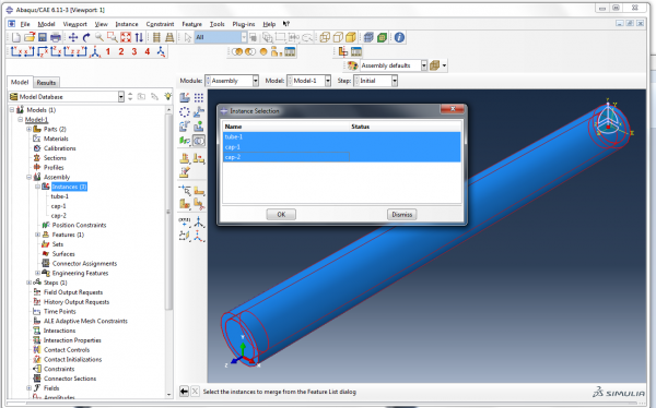
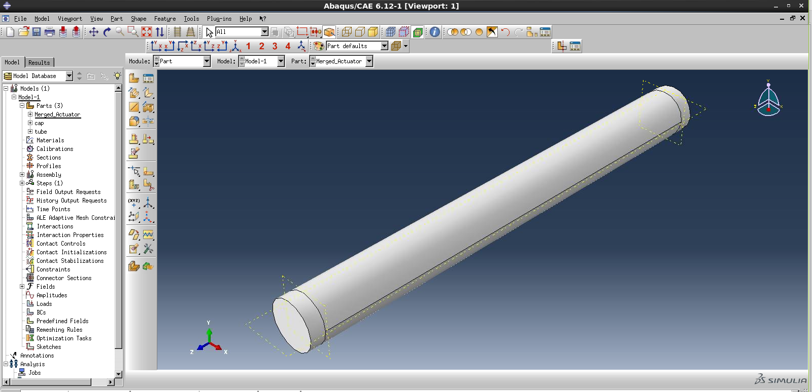
Now we have created a new part called ‘Merged_Actuator’, and an instance of this part has been added to the assembly.
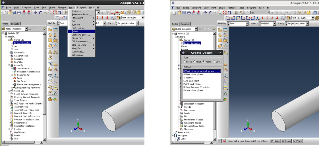
For a bending actuator, we need to partition the actuator so we can assign different materials to the top half and bottom half of the actuator.
Double click on 'Merged_Actuator' under ‘Parts’ in the model tree. This will allow you to edit the part.
In the main toolbar, go to Tools->Datum. Select Plane, Offset from principal plane. Choose the X-Y plane, and enter 5 (the cap thickness) as the offset amount. Repeat, choosing 160 as the offset amount.
Now go to Tools->Partition. Select Cell and Use datum plane. Click on the first datum plane you created, and click Create partition, to complete the partition definition.
Now click on the main body of the actuator (the cell to be partitioned), click ‘Done’, select the second plane you created and click Create Partition.
Now the caps have been partitioned from the rest of the actuator.
To partition the actuator into its top and bottom halves, define another datum plane: go to Tools->Datum. Select Plane, Offset from principal plane. Choose the X-Z plane, and enter 0 as the offset amount.
Again, go to Tools->Partition. Select Cell and Use datum plane. Select the middle portion of the actuator as the cell to be partitioned, and select the datum plane you just created, and click Create partition, to complete the partition definition.
Now we can assign different materials to the top, bottom and caps of the actuator.
Step 1b: Create Fibers
Create fibers
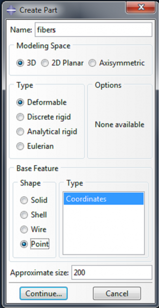 | The second major component of the actuator is the set of fibers around the outside. To create these fibers, double click on Part again. Name the part ‘fibers’ and make it a 3d Point. Hit enter to accept the default of (0.0,0.0,0.0) as the coordinates. |
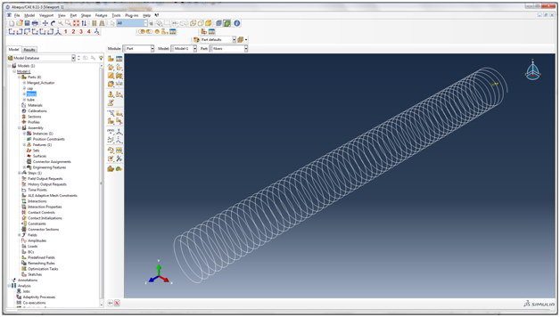
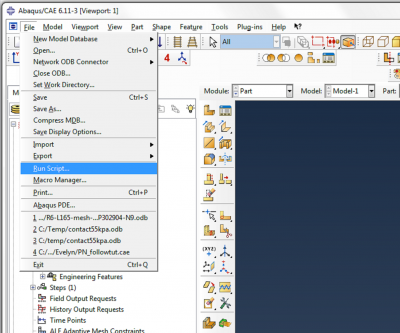 | Go to File->Run Script. Browse to the file fibers.py and run it. This file creates a helical wire structure, with radius 8.35mm, height 163mm, and fiber angle 3°. An actuator with this fiber angle will extend and twist upon pressurization. Note: the fiber angle can be changed by modifying the parameter ALPHA in fibers.py. For a bending actuator, run the file fibers_bending.py. This will create a symmetric arrangement of fibers (fibers at equal and opposite angles). |
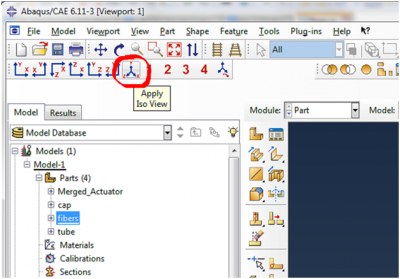 | To view the fibers, click on Apply Iso View. |
Add fibers to assembly
Now we will make a set containing the fibers, as we will use this later in the model. In the model tree, expand Parts->Fibers and double click on Sets.
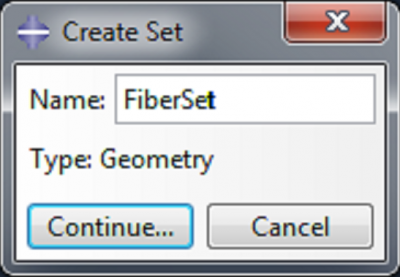 | Name the set FiberSet and click Continue. |
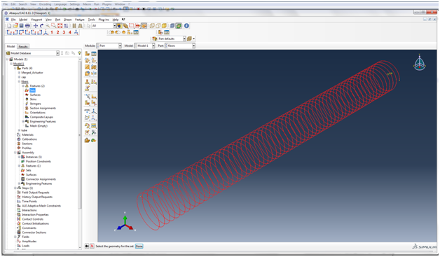
Click on the fibers to select them as the geometry for the set, and click Done.
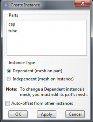
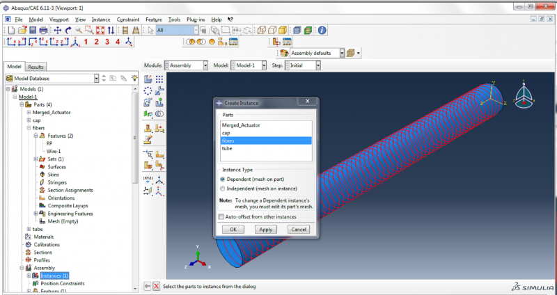
To add an instance of the fiber to the assembly, expand the assembly tree, double click on Instances, select ‘fibers’ in the Create Instance box, and click OK.
Step 2: Create and assign materials
Create and assign materials
Next we will create the two materials used in this model: Elastosil (for the elastomeric tube) and Kevlar (for the fibers).
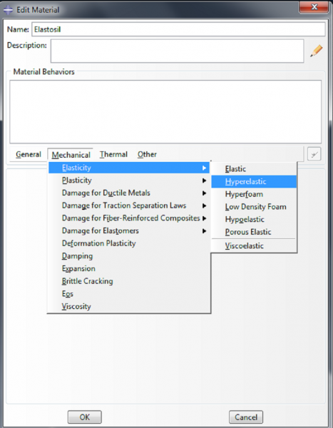
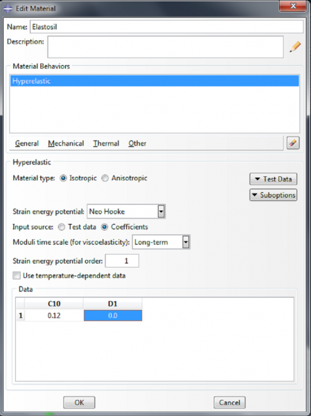
To create the first material, double click on Materials in the model tree. Name the material ‘Elastosil’. This is a nonlinearly elastic material, so we assign it the property Mechanical->Elasticity->Hyperelastic. We will model it using a neo-Hookean strain energy potential. Choose ‘Coefficients’ as the input source, with C10=0.12MPa and D1=0.0. Click OK.
 |  |
For a bending actuator, instead of defining the Elastosil material, define the materials Smooth-Sil 950 and Dragon Skin 10, as follows:
Double click on Materials in the model tree. Name the material ‘DS10’. This is a nonlinearly elastic material, so we assign it the property Mechanical->Elasticity->Hyperelastic. We will model it using a neo-Hookean strain energy potential. Choose ‘Coefficients’ as the input source, with C10=0.0425MPa and D1=0.0. Click OK.
Make a second material and name it 'SS950'. Again, we will model it using a neo-Hookean strain energy potential. This time set C10=0.34MPa and D1=0.0.
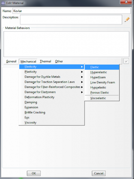
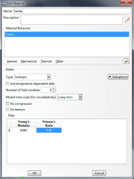
To make the material for the fibers, we double click on Materials again. Name this material ‘Kevlar’. We model it as a linearly elastic material, with properties Mechanical->Elasticity->Elastic. Enter 31067 MPa for the Young’s modulus and 0.36 for the Poisson’s ratio. Click OK.
 |  |
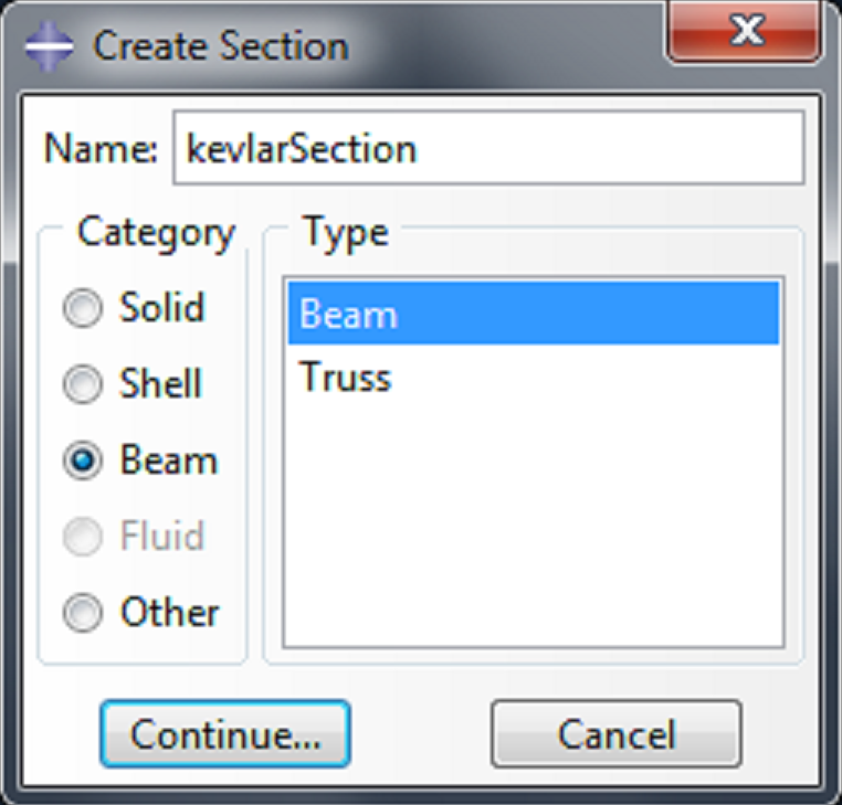
 |
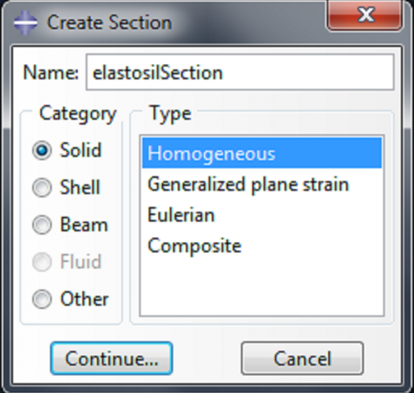
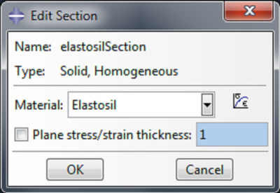
Name the section elastosilSection. Click Continue, choose Elastosil as the material, and click OK. For a bending actuator, instead of defining the section elastosilSection, use the materials DS10 and SS950 to define DS-section and SS-section. |
 |  |
 |
|
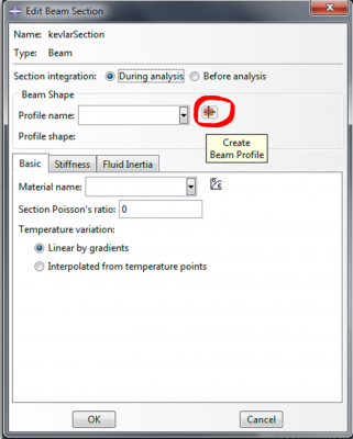 |
|
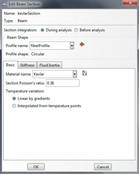
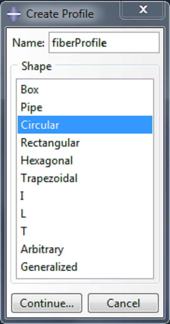 | Name the profile fiberProfile, and select ‘Circular’ as the shape. |
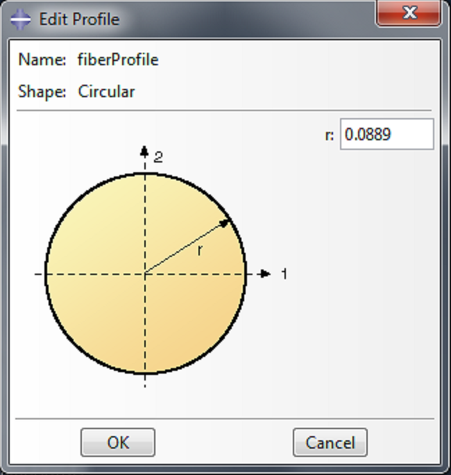 | Click Continue, enter 0.0889 as the radius ‘r’ and click OK. This models the fiber as a beam structure with a circular cross section. |
 |
|
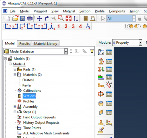
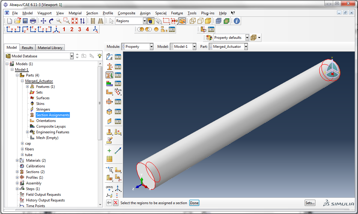
Now we need to assign a material to each of the parts. Expand Merged_Actuator under Parts and double click Section Assignments. Select the actuator and click Done.
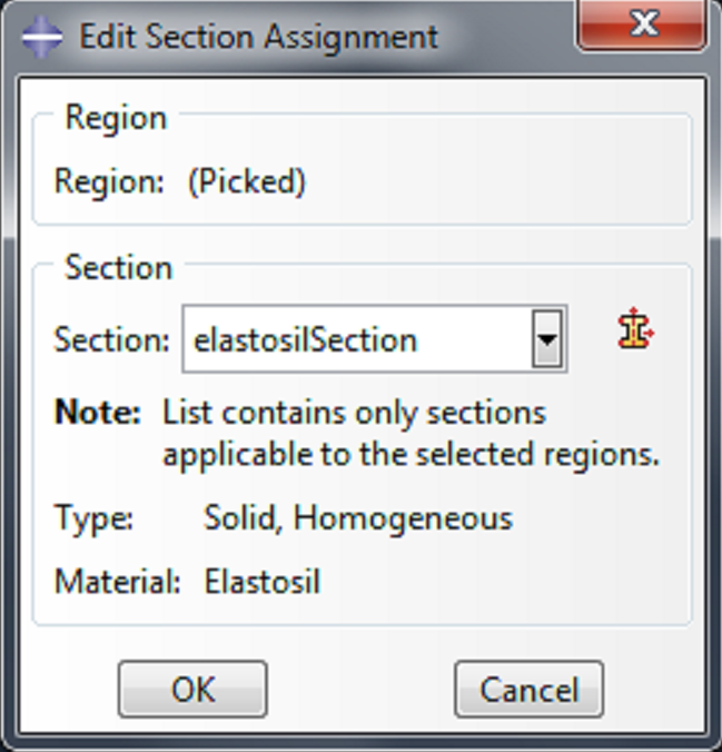 | Click OK in the ‘Edit Section Assignment’ box. |
For a bending actuator, assign SS-section to the caps and the bottom half of the actuator. Assign DS-section to the top half of the actuator.
Expand fibers under Parts and double click Section Assignments. Select the fiber and click Done.
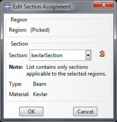 | Click OK in the ‘Edit Section Assignment’ box. |
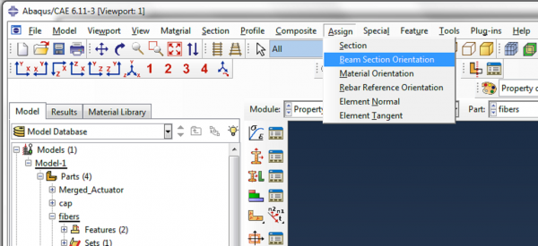 | In the main toolbar, click Assign->Beam Section Orientation. Select the fiber and click Done.
|
Step 3: Create surfaces and loads
Create surface for applying pressure
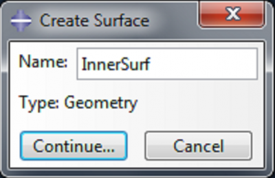
We will want to apply a pressure load to the internal surface of the actuator, so we first need to create this surface. Expand Merged_Actuator under Parts, and double click on Surfaces. Name the surface ‘InnerSurf’.
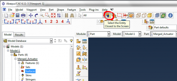
In order to access the inner surfaces, we need to deselect the Select Entity Closest to Screen icon.
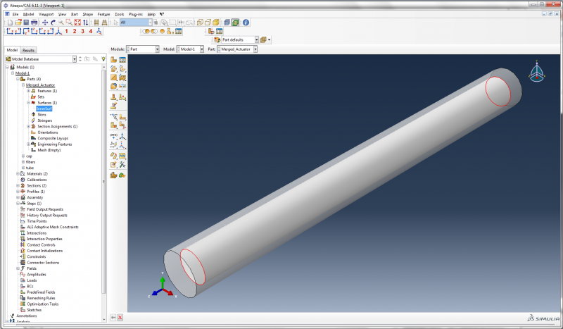
Now hold the shift key and select the inner surfaces of the actuator (the curved surfaces and the two flat surfaces) and click Done. To check that the new surface has been defined correctly, you can go to Surfaces and click once on ‘InnerSurf’, and check that the correct surfaces are highlighted.
Later, we will also need to refer to the outer surface of the actuator, so under Parts->Merged_Actuator, double click on Surfaces again. Reselect Select Entity Closest to Screen. Name the surface ‘OuterSurf’. Select the outer curved surface of the actuator and click Done.
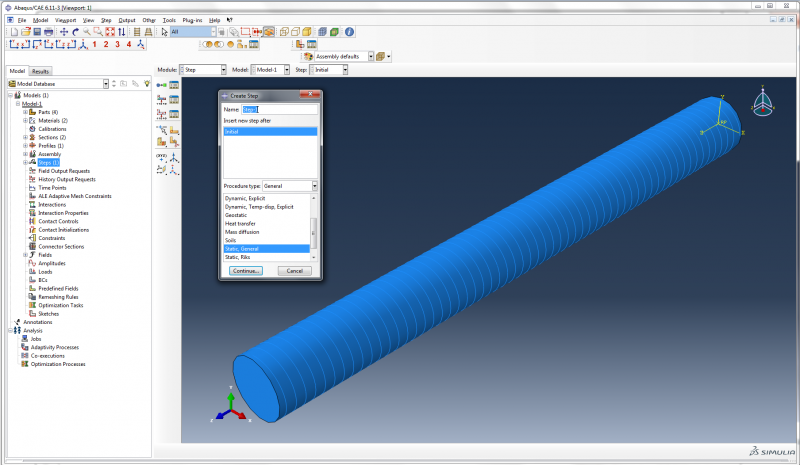
Create Step
In the model tree, double click on Steps, to create the step in which we will apply the pressure load. Accept the default options of a static general step.
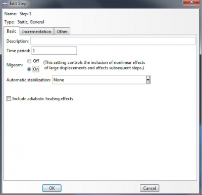
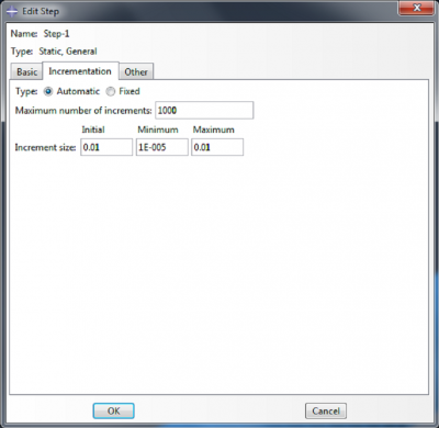
In the ‘Edit Step’ dialog box, select Nlgeom ‘On’ under the Basic tab. Under the Incrementation tab, set 1000 as the Maximum number of increments, 0.01 as the Initial increment size, 1E-5 as the Minimum increment size, and 0.01 as the Maximum increment size. Click OK.
 |
 |
Define Boundary Conditions
For our boundary condition, we will fix the actuator completely at one end. Double click on BCs in the model tree. Choose Displacement/Rotation as the type of boundary condition and click Continue.
 |
|
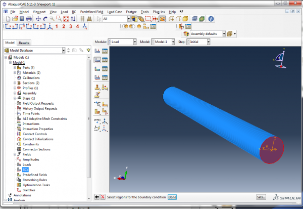
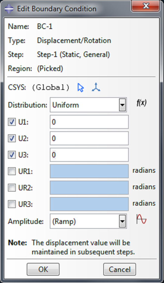 |
We want to impose zero displacement on this actuator face, so check the boxes next to U1, U2 and U3, and accept the default displacement values of 0.0. |
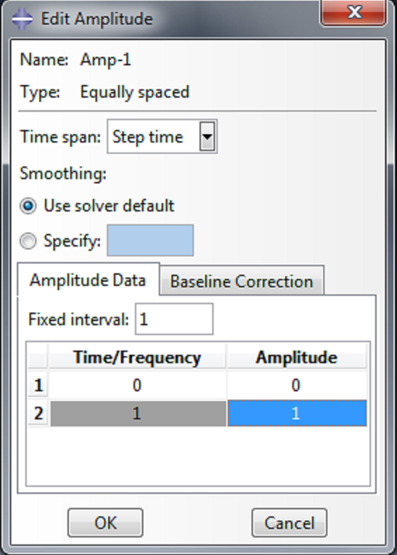
To control the rate at which the pressure load is applied, we create an amplitude. Double click on Amplitudes, and select ‘Equally spaced’. In the ‘Edit Amplitude’ dialog box, enter [0,1] in the coumn under ‘Amplitude’. This will apply the load linearly as a function of time.
 |
 |
Apply load
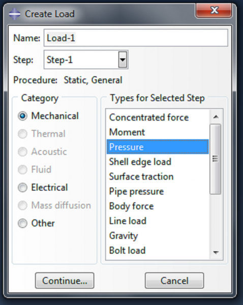 |
Now we define the pressure load, by double clicking on Loads. Select ‘Pressure’ as the load type, and click Continue. |
When prompted to select a surface for the load, click on the Surfaces button at the bottom right of the screen.
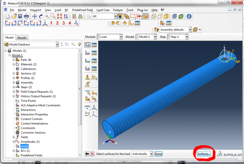
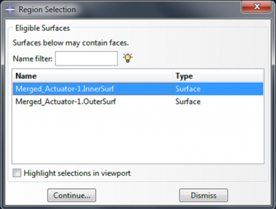 |
Select ‘Merged_Actuator-1.InnerSurf’. |
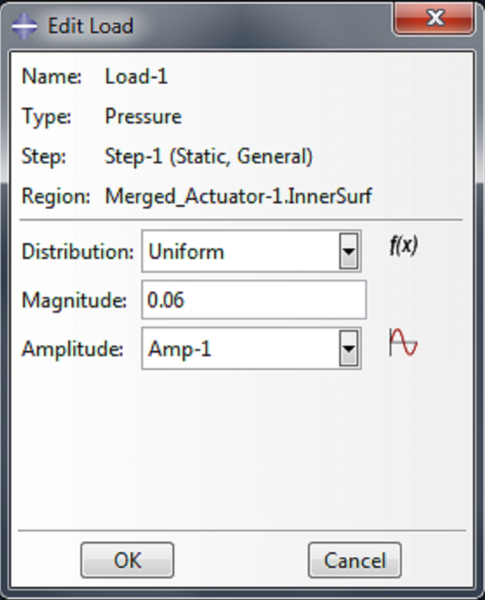 |
Enter 0.06 as the magnitude in the ‘Edit Load’ dialog box, and select ‘Amp-1’ as the amplitude. |
Step 4: Mesh
Mesh
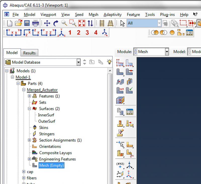
Double click on Parts->Merged_Actuator, then double click on Parts->Merged_Actuator->Mesh.
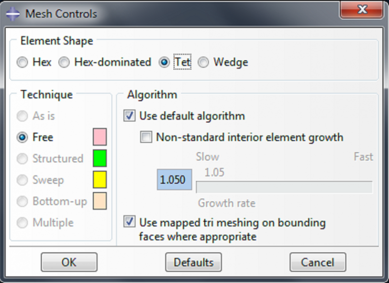 |
Go to Mesh->Controls. Select ‘tet’ as the element shape and click OK. |
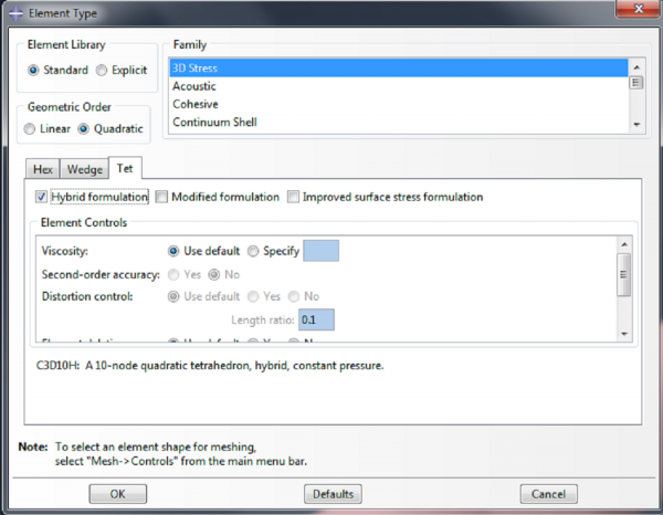 |
Go to Mesh->Element Type. Select ‘Quadratic’ as the Geometric Order, and under the Tet tab, check the box for ‘Hybrid formulation’. |
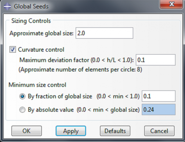 |
Go to Seed->Part, and choose 2.0 as the ‘Approximate global size’. The appropriate size to enter here depends on the size and geometry of the part being modeled, and the amount of deformation it undergoes. |
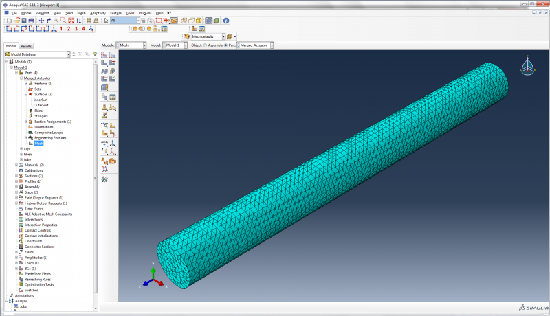
Go to Mesh->Part, and click Yes to confirm it’s ok to mesh the part.
Under fibers in the model tree, double click on Mesh. Go to Mesh->Element Type. In the ‘Element Type’ dialog box, choose quadratic beam elements (B32) and click OK.
Go to Seed->Part, enter 1.0 as the ‘Approximate global size’, and click OK.
Finally, go to Mesh->Part to mesh the fibers.
Step 5: Add tie constraint
Add tie constraint
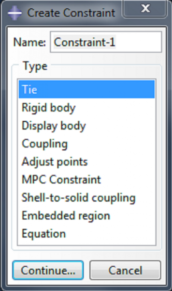
The fibers and the elastomeric tube need to be connected to each other in some way, and this connection is modeled as a ‘tie constraint’, which ties the fibers to the surface of the actuator. To apply this constraint, double click on Constraints in the model tree. Accept the default type of ‘tie’ and click Continue.
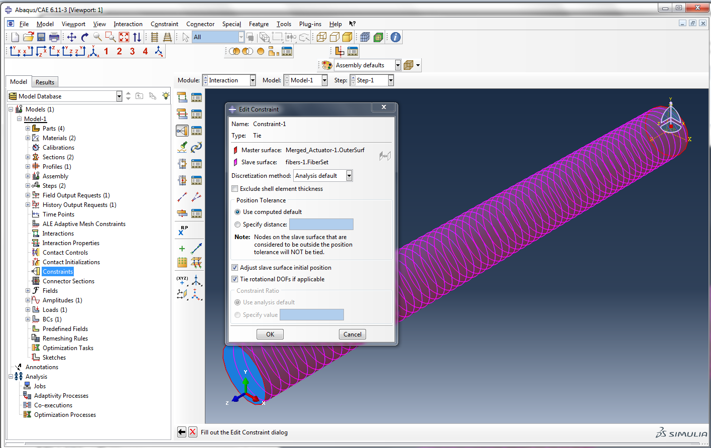
- Choose ‘Surface’ as the master type.
- Click on Surfaces in the bottom right corner, select ‘Merged_Actuator-1.OuterSurf’, and click Continue.
- Choose ‘Node region’ as the slave type. Select ‘fibers-1.FiberSet’ and click Continue.
- Click OK in the ‘Edit Constraint’ dialog box to impose the constraint.
Step 6: Create and run job
Create and run job
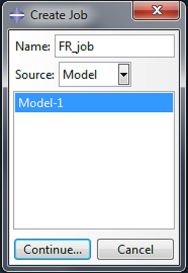
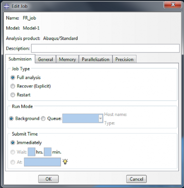
In the model tree, double click on Jobs. Give the job a name, and accept all the default settings. In the model tree, right-click on the job you just created, and select Submit.
 |
 |
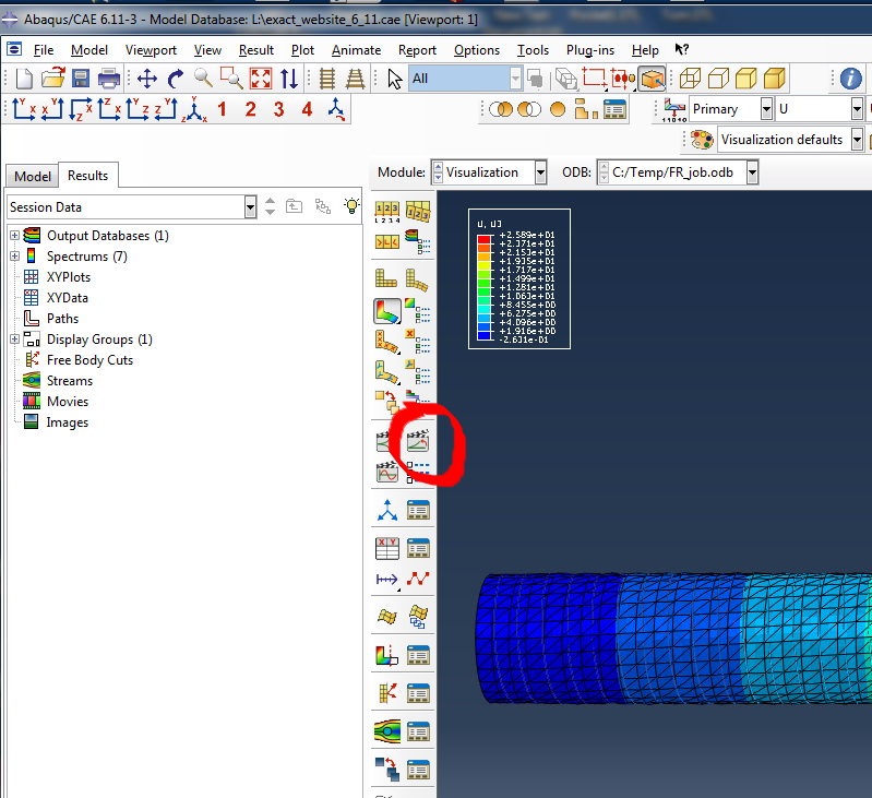
View Results
When the job has completed, right-click on the job name and select Results.
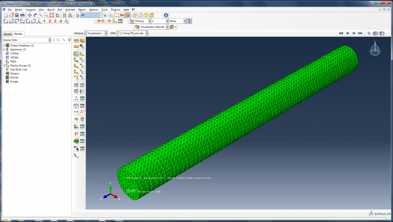
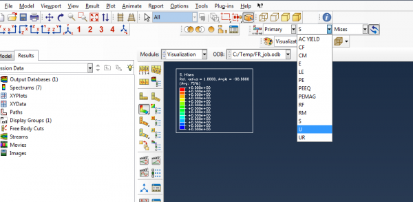
The default result displayed is the von Mises stress. This can be changed using a dropdown menu. For example, you can choose to visualize U3, the displacement in the z direction, to see how much the actuator is extending.
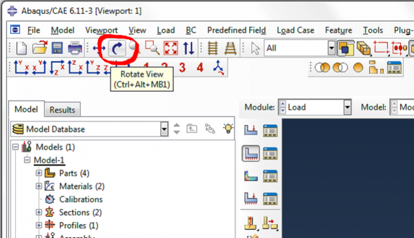
The navigation buttons at the top right of the screen can be used to scroll through the step increments.
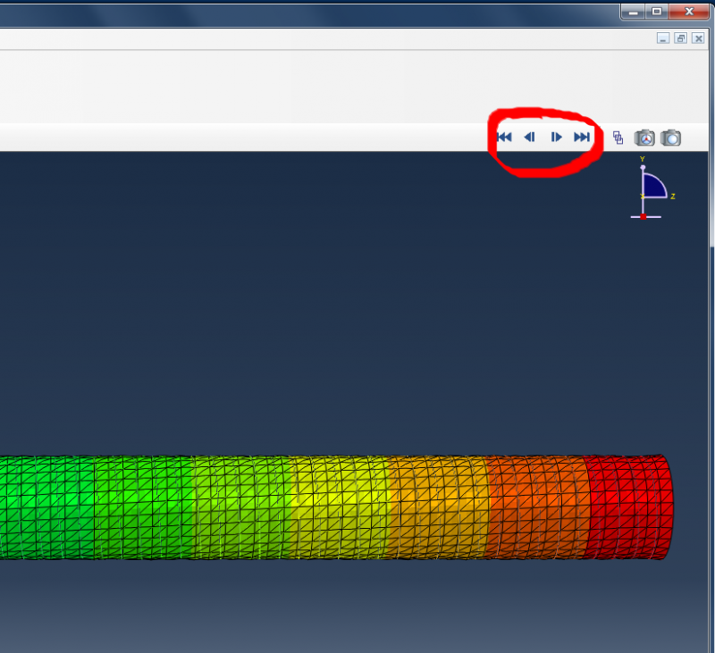
To view an animation of the solution, click on the animate button.