Fabrication
In this section, we will present the fabrication of a single actuation module. The actuation module is composed of four main components: the source code of the running mechanism, the main electronics circuitry, the tendon and pulley mechanism, and the covering container box. Follow the steps in this section to learn how to build all of these components.
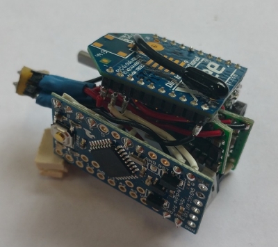 |
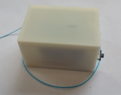 |
| The main circuitry inside the actuation module | The complete box with the electronics and tendon mechanism inside. |
Bill of Materials
This section provides you information about the materials used in the project with links to the suppliers. Please note that most of the suppliers listed here are from UK, but the materials can be found globally. You can find the complete bill of materials here.
Robot Construction
|
|
|
|
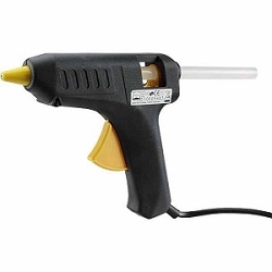
Pattex Glue Gun |
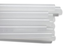
Glue Sticks |
Please note that a glue gun and glue sticks are already enough to build a soft robot. But feel free to use any other supporting material to make your funkier!
Actuation Module
|
|
|
|
|
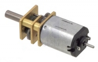
Pololu 100:1 HP Micro Gear Extended Shaft Motor |
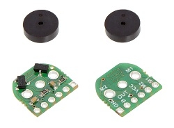
Pololu Magnetic Encoders |
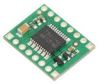
Toshiba TB6612FNG Motor Driver Carrier |
|
|
|
|
|
3.7V 980mAh Rechargeable LiPo Battery |
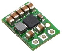
5V Step-up Voltage Regulator |
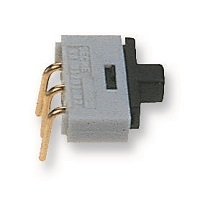
Power Switch |
|
|
|
|
|
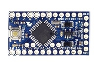
3.3V 8 MHz Arduino Pro Mini |
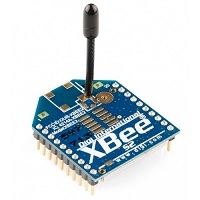
XBee (Zigbee) S2 |
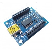
XBee USB Adapter |
 |
 |
 |
|
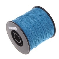
0.55mm Dyneema Fishing Line |
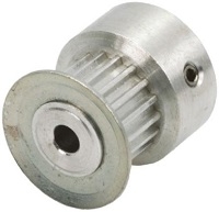
3mm Shaft Belt Pulley |
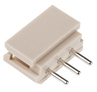
Molex SPOX 5267 Housing |
|
|
|
|
|
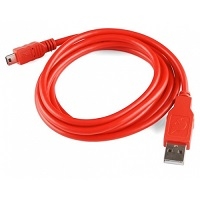
Mini USB Cable |
26AWG Black, Red, White Wire |
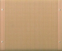
Prototyping Board |
|
|
||
|
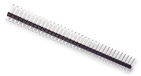
Breakaway Pins |
Tools
 |
 |
 |
|
Wire Stripper |
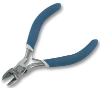
Wire Cutter |
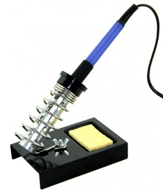
Soldering Iron |
|
|
||
|
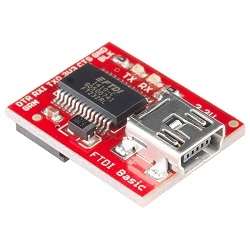
FTDI 3.3V Programmer |
Equipment
 |
 |
 |
|
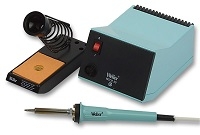
Soldering Station |
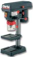
Bench Drill |
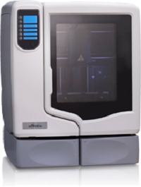
Stratasys uPrint 3D Printer |
Step 1 - XBee and Arduino
XBee Setup
In this step we will configure one receiver (router) and one transmitter (coordinator) XBee. We will use free software XCTU for this configuration. Users can find more information about XBee programming in this software's website.
|
1. Plug in the XBee to the USB adapter and plug it to your PC. After your computer finishes downloading the necessary drivers run XCTU. 2. When purchased, all XBee S2 comes with Baud rate 9600 and router as default. Add the radio module by searching the COM ports with 9600 baud rate devices. 3. When you add the radio module, it will appear on the left part of the XCTU screen. Click on the radio module and software will display all the details about the device on the right. |
 |
 |
|
4. As the first XBee device will be the router (this will be the one we will put in the module box), we will leave it as a Router AT and continue configuring other necessary details. 5. We need to change four important parameters for this Router XBee: PAN ID, DL (Destination Address Low), BD (Baud Rate) and RO (Packetization Timeout). Find these parameters and change them to values in order: 3039, 0, 115200 and 0. 6. After changing these values click the write button and finish programing this XBee. Unplug this router XBee from the adapter. |
 |
|
7. Plug the other XBee which will become the coordinator or the transmitter that will stay attached to your PC to send commands to the module. 8. Add the radio device like the previous one and click on it to display its settings. 9. As by default each XBee is set to be Router AT, we will change this one to a Coordinator AT. Click the update firmware button to see the list of possible firmwares. Find ZigBee Coordinator AT from that list and click finish to update the device. |
 |
|
10. When you click to update the firmware, the device will be re-programmed to be a Coordinator AT. You can see that the symbol of the device on the left will be changed. 11. Similar to the previous case, we will update some values of this coordinator device: PAN ID, DL (Destination Address Low), BD (Baud Rate) and RO (Packetization Timeout). Find these parameters and change them to values in order: 3039, FFFF (default value), 115200 and 0. 12. Click on write settings button and finish the update. You can leave this XBee connected to your PC |
 |
| Note: Notice that we have selected the PAN ID and Baud Rate same for both devices. PAN ID is the network ID, this should be the same for all the other modules you want to command with your coordinator. Baud Rate should also be the same so that data transfer can be done with same transmit settings. | |
Arduino Programming
In order to program our Arduino Pro Mini, we will use the free software from Arduino. The source code that will upload to our arduino can be found here.
|
1. Plug your FTDI programmer with the mini USB cable to your PC. Your operating system will download the necessary drivers for the FTDI chip. 2. Solder 5 pin headers to your Arduino's programming pins. 3. Connect the FTDI chip to the Arduino's soldered pins and wait for your operating system to download the necessary drivers. 4. Run the Arduino software. |
 |
|
5. Open the Arduino source code we provide. 6. Select the "Arduino Pro or Pro Mini (3.3V, 8MHz) w/ ATmega328" board from Tools-> Board 7. Select the COM port where the FTDI is attached from Tools->Board 8. You can find the unit ID of your module in the code line 65 as "myID" and line 66 team ID as "allID". By default we set myID to M1 and teamID to MA1. If you want to build more modules, change myID to M2, M3 and so on. 9. Upload the code by clicking the upload button. 10. After the successful upload, unplug the Arduino from the FTDI board. |
 |
| 11. IMPORTANT: As we are going to use XBee with the Arduino, we will have to solder it to the TX and RX pins of the Arduino board. If you will need to re-upload a code to your Arduino, you have to make sure that the TX and RX pins are desoldered from the XBee device. Otherwise your code will not upload properly as FTDI board is also using these pins to upload data to Arduino. | |
Serial Communication
| When the coordinator XBee is connected to the PC, any serial communication software which can send and receive data from the serial (COM) ports of the PC can be used to communicate with the modules. XCTU software allows the bi-directional serial communication. Users are also free to use serial communication in MATLAB and can start with this sample code. |  |
Step 2 - Soldering - Part 1
Circuit Pinout
|
|
| The figure above shows the pinout of the circuitry in the actuation module box. A protoboard is distributing the power to the logic circuits. All the Vin and GND of the logic circuits are connected to the corresponding pins on the protoboard. As the motor can drive high current, its power route is separated from the logic circuit. Motor gets the positive voltage from the step up regulator and its negative voltage (GNDM) is connected to GNDM on the protoboard. M1 and M2 pins are directly soldered to the motor's own positive and negative pins when the encoder is placed on the extended shaft behind the motor. |
Step 1
|
1. Make sure that Arduino's programming pins are desoldered after uploading the code. 2. Solder Tx0 pin of Arduino to Din pin of XBee ( wire length: 3cm ) 3. Solder RXI pin of Arduino to DOut pin of XBee ( wire length: 3cm ) |
 |
|
4. Make sure that the unused pins of XBee is either insulated or cut off. In our implementation we cut the unused pins to avoid unwanted shorts between open pins. 5. Place a plastic tape on the metal surface behind the XBee to avoid short circuits. |
 |
Step 2
|
1. Solder PWMA pin of motor driver to Pin 6 of Arduino (wire length: 4 cm) 2. Solder AIN2 pin of motor driver to Pin 7 of Arduino (wire length: 4 cm) 3. Solder AIN1 pin of motor driver to Pin 8 of Arduino (wire length: 4 cm) 4. Solder STBY pin of motor driver to Pin 9 of Arduino (wire length: 4 cm) 5. Solder AO1 pin of motor driver to a 3cm length cable 6. Solder AO2 pin of motor driver to a 3cm length cable |
 |
Step 3
|
1. Carefully place the encoder to extended shaft of the motor. 2. Solder M1 and M2 pins of the encoder to the motor pin headers. 3. Place the magnetic disk on the extended shaft until a small gap between the sensors on the encoder. 4. Solder Out B of encoder to Pin 2 of Arduino (wire length: 5 cm) 5. Solder Out A of encoder to Pin 3 of Arduino (wire length: 5 cm) |
 |
Step 4
|
1. Cut a 4x2 slot from the prototyping board. 2. Make a triple branch with wire lengths 3,4.5 and 4.5 cm for logic Vin. Solder it to a breakaway pin and to (1,1) of proto-board. 3. Make a double branch with wire lengths 4 and 4.5 cm for logic Vin. Solder it to a breakaway pin and to (2,1) of proto-board. 4. Make a triple branch with wire lengths 4, 4.5 and 4.5 cm for logic GND. Solder it to a breakaway pin and to (1,2) of proto-board. 5. Make a double branch with wire lengths 4 and 4.5 cm for logic GND. Solder it to a breakaway pin and to (2,2) of proto-board. |
 |
Step 5
|
1. Cut out the middle pin of the molex connector and the leftmost pin of the switch. 2. Solder the pin on the flat edge of molex to rightmost pin of the switch (wire length: 3cm) 3. Solder a 5cm length wire to the pin on slope edge of molex. 4. Solder a 5 cm length wire to the middle pin of the switch. |
 |
Step 2 - Soldering - Part 2
Circuit Pinout
|
|
| The figure above shows the pinout of the circuitry in the actuation module box. A protoboard is distributing the power to the logic circuits. All the Vin and GND of the logic circuits are connected to the corresponding pins on the protoboard. As the motor can drive high current, its power route is separated from the logic circuit. Motor gets the positive voltage from the step up regulator and its negative voltage (GNDM) is connected to GNDM on the protoboard. M1 and M2 pins are directly soldered to the motor's own positive and negative pins when the encoder is placed on the extended shaft behind the motor. |
Step 6
|
1. Solder the 4.5cm long Vin wire from the triplet to the Vin pin of Arduino. 2. Solder the 4.5cm long GND wire from the triplet to the GND pin of Arduino. 3. Solder the 4.5cm long Vin wire from the triplet to the Vin pin of motor driver. 4. Solder the 4.5cm long GND wire from the triplet to the GND pin of motor driver. |
 |
Step 7
|
1. Solder the 4.5cm long Vin wire from the couple to the Vin pin of step up regulator. 2. Solder the 4.5cm long GND wire from the couple to the GND pin of step up regulator. 3. Solder VOut pin of step up regulator to VMOT pin of the motor driver (wire length: 3cm) |
 |
Step 8
|
1. Solder the 4cm long Vin wire from the couple to the Vin pin of encoder. 2. Solder the 4cm long GND wire from the couple to the GND pin of encoder. 3. Solder the 3cm long wire from the AO1 pin of motor driver to the M1in pin of encoder. 3. Solder the 3cm long wire from the AO2 pin of motor driver to the M2in pin of encoder. |
 |
Step 9
|
1. Solder the 5cm V+ wire from the power switch to (4,1) pin on the proto-board. 2. Solder the 5cm V- wire from the power switch to (4,2) pin on the proto-board. 3. Solder GNDM pin of motor driver to (3,2) pin on the proto-board (wire length: 3.5cm) |
|
Step 10
|
1. Solder the 3cm long Vin wire from the triplet to the Vin pin of XBee. 2. Solder the 4cm long GND wire from the triplet to the GND pin of XBee. |
 |
Final

Your circuit should look like this if this tutorial was clear enough !
Step 3 - Pulley and Tendon
Step 1
| 1. Drill a 1.5mm radius hole on the beginning of the belt space of the pulley. | 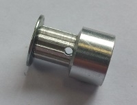 |
Step 2
|
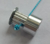
1. Cut a piece of wire from the Dyneema tendon line whose length depends on your preference. 2. Put the tendon through the hole you opened on the pulley. 3. Make a knot large enough to block the hole and avoid the tendon to go loose when its pulled. |
 |
Step 4 - Fitting in the Box
Step 1
|
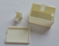
1. Use the STL files we provide to 3D print the three main components of the module box. 2. Depending on the resolution of your 3D printer, you might need to file the sides of the motor holder piece if it does not slide easily through its section on the container box wall. |
 |
Step 2
|
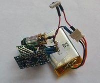
1. Connect the LiPo battery to the molex connector in your circuit. 2. Switch on the power switch to make sure the circuit is working. Note: If you see a smoke or a smell burning, take the battery out immediately and check if your circuit is correctly done. |
 |
Step 3
|
1. Slide the motor through the motor holder component. Make sure the motor cannot move freely within its hole. If necessary stick pieces of paper to hold the motor in place. 2. Use a 1mm Allen Key to screw the pulley on to the motor shaft. |
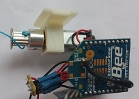 |
Step 4
|
1. Place the battery into the container box. 2. Slide the power switch through its dedicated hole on the back side of the container box. |
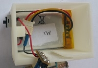 |
Step 5
|
1. Place the tendon wire through the hole on the side of the container box. Avoid tangling. 2. Make sure the wires connecting to the battery are flat on the battery surface to make space. |
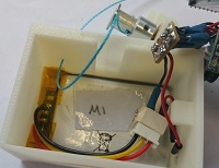 |
Step 6
|
1. Place the motor holder on the designated slides on the container box. 2. Make sure the tendon wire, circuitry and the wires can be pushed into the box without any tangling. |
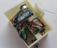 |
Step 7
| 1. Push the whole circuit along with the motor holder into the container box. The container box is large enough to contain all of these components without them poking out from the top of the box. | 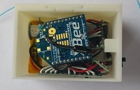 |
Step 8
|
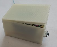
1. Place the lid on the container box making sure that the extensions on the lower surface of the lid are facing the inlets on the front wall of the container box. 2. Slide the lid forward and then and push it downwards to shut the container box. |
 |
Final
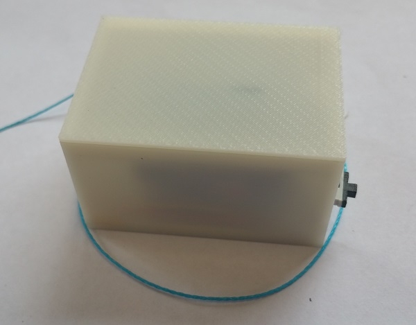
Your actuation module should look like this at the end of this tutorial !
