Smart Braids
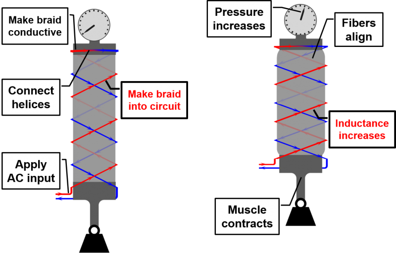
“Smart Braids” are conductive reinforcing fibers that provide a way of sensing the deformation and force output of fiber-reinforced actuators without any external transducers. Typically the length of the actuator would be deduced from a sensor attached to a rigid link (like a potentiometer or an optical encoder). Smart Braids provide a soft sensor that sense the actuator contraction without external mechanical parts. A Smart Braid changes in inductance and resistance in response to the movement and force output in fiber-reinforced actuators. This can be accomplished by using conductive fibers in a circuit to form the reinforcing structure of a Pneumatic Artificial Muscle, FREE, or other fiber-reinforced actuator. When the actuator contracts, the fibers become more aligned and the inductance increases. The inductance is related to the strength of the magnetic field created by the wires. When the wires are aligned, the magnetic field created by each wire builds on the magnetic field created by its neighbors and the inductance is high. When the wires are not aligned, they cancel each others magnetic fields and the inductance is lower. If the wires are far apart, they have a smaller effect on each other's fields. When the wires are connected in series, these small changes in magnetic field intensity can turn into a valuable signal.
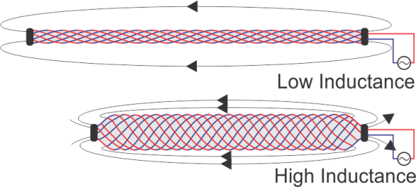
Additionally, external forces and internal pressure create a strain in the fibers that can be measured through changes in resistance (similar to a strain gauge). That is, the tension on the wires causes them to stretch slightly. As they stretch, the current in the wires is forced to travel through a narrower space and it encounters more resistance. We can measure this electrical resistance to estimate the amount of force the wires are being subjected to. We tested the "Smart Braid" by building Pneumatic Artificial Muscles with a braided sleeve made out of off-the-shelf wire. We found we can characterize the actuator contraction quickly and accurately by measuring the inductance of the braid.
| Some of the information contained in this web site includes intellectual property covered by both issued and pending patent applications. It is intended solely for research, educational and scholarly purposes by not-for-profit research organizations. If you have interest in specific technologies for commercial applications, please contact us here. |
Design
The basic choices for designing a McKibben Actuator are the length, diameter and winding angle (θe). The length and winding angle determine how far the actuator will contract. The winding angle is the angle of the fibers when the actuator is fully extended. As the actuator contracts, the angle increases until some point before 54.7o. We've been able to achieve about a 20% contraction with a 20o winding angle. Here are some things to keep in mind when designing your smart braid:
- Smaller winding angles increase the stress on the fibers.
- Larger winding angles lead to a smaller overall contraction but lower stress on the fibers.
- Larger diameters create more force during the contraction.
- The force will be greatest when the actuator is fully extended and will decrease as the actuator contracts.
The Smart Braid introduces additional design choices about the wires. The wires need to be chosen so that the stress in the wires is not too great and their resistance is low enough to measure the inductance of the sensor. A relatively large diameter wire can achieve these goals.
Braid Model
We can model the way that braid will contract by adapting equations presented by Chou and Hannaford.
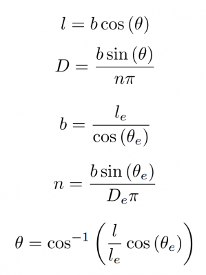
The subscript "e" refers to the condition of the braid in its fully extended, unpressurized condition. "b" is the length of the helices that make up the braid. "n" is the number of turns each helix makes around the axis. "θ" is the angle that the wires of the braid make with the long axis. "D" is the diameter of the braid. "l" is the length of the braid.
Design Calculator
Smart Braids need to be designed to provide both sensor and structure for the actuators they surround. It can be difficult to balance the demands of actuator design with Smart Braid performance. To aid in this design process, we've created a design calculator (attached to this page). The design calculator allows you to make your design feasible. It makes sure you can fit the wires around the tube and checks the forces on the wires to ensure they won't break. If you plan on measuring inductance by using a capacitor, it lets you know if you're choice of capacitor will result in an oscillating circuit with a measurable frequency.
| smart_braid_design_caluclator_0.xlsx | 12 KB |
Modeling
Smart Braids work by creating a structure that changes inductance over the course of the actuator stroke. For McKibben Muscles, the change in inductance can be modeled with the long solenoid approximation. For more accurate results, or for other types of fiber-reinforced actuators, the Neumann formula can be integrated.
Long Solenoid Approximation
Each right-handed helix of the Smart Braid is connected to an adjacent left-handed helix. In this configuration, the current moves up the actuator along one hand of helix and down the actuator along the other hand. The current always circles the axis of the actuator in the same direction like a solenoid. This allows us to use the Long Solenoid equation to predict the change in inductance.
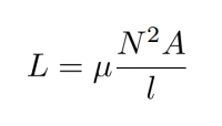
As McKibben Muscles contract, their length, l, decreases while their cross-sectional area, A, increases. The total number of times that the current circles the axis, N, remains constant. When using rubber tubes and air for the inside of the solenoid, the magnetic permeability of the core can be assumed to remain constant at the level of vacuum (4*π x10^-7).
Neumann Formula
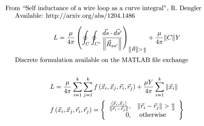
Another way of calculating the inductance of the Smart Braid is through the Neumann Formula. If we assume that the current-carrying wires are very thin, and there are no sharp corners in the circuit, we can use a double curve integral to calculate the inductance. The core element of the Neumann Formula is the expression that is summed over the course of the integral.
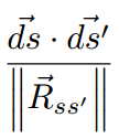
The dot product in this expression shows us that fiber segments that are aligned have a positive effect on the overall inductance of the circuit. This effect is inversely proportional to the distance between the segments. If the current in the segments flows in opposite directions, the effect on the inductance is negative.
We created a tool for calculating inductance via the Neumann formula available through the MATLAB File Exchange.
Inductance Measuring Techniques
Two off-the-shelf inductance measurement techniques are described below. The first uses a commercially available LCR meter. The second method is much less expensive but more difficult to implement.
NI PXI-4072 FlexDMM and LCR Meter
This device permits inductance to be measured at up to 40 times per second. It works by comparing the magnitude of the impedance at high and low frequencies. It requires an NI PXI chassis to function. We found that this device works well when the resistance of the braid is low. Because the excitation frequency of this sensor is relatively low (30 kHz), large electrical resistance in the Smart Braid causes the meter to malfunction. The large, 22 AWG wire actuators we tested had sufficiently low resistance.
TI LDC, Inductance to Digital Converters
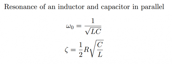
These chips allow one to measure inductance very quickly (think kHz). They also comes with handy evaluation modules. The chips requires that the Smart Braid be wired in parallel with a capacitor. This parallel combination creates a resonant tank circuit with a natural frequency that varies with the changing inductance. The capacitor needs to be selected so that the natural frequency is within the specs of the chip and so that the damping ratio of the tank circuit is very low.
Stress and Resistance Considerations
Smart Braids need to be designed to bear the high-stresses of pressurized actuation and have low resistance. The wires that make up the braid also need to be able to withstand repeated bending and cyclic stress. For both methods of inductance measurement that we present, high circuit resistance (and relatively low inductance values) can make the measurement of inductance difficult. For these reasons, the ideal wire material would probably be thinly-insulated, stranded aluminum wire. Aluminum has both high conductivity and high tensile strength. Due to the limited commercial availability of aluminum wire, however, we use copper wire in our experiments.
The stress in the wires can be calculated using an equation presented by Davis and Caldwell.
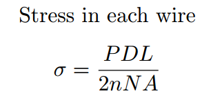
P is the pressure in the actuator, D is the diameter, L is the length, n is the number of turns each helix makes around the long axis, N is the total number of helices, and A is the cross-sectional area of the wire.
Fabrication
The braid is constructed by weaving wire over a 3D-printed template. The template is designed to make actuators that have a 20 degree winding angle when surrounding a tube with a 3/8" outer diameter. The template is designed so that the braid length can be varied in multiples of 10 cm (10 cm, 20 cm, 30 cm etc.). The actuator we present here is designed to work with a 30 cm braid.
Bill of Materials
| Quantity | Unit (ea,pkg,ct) | Item# | Description | Unit Price | Link |
| 100 | ft | Daburn 2671/22 | Black 22 AWG Ultra Flexible Wire | $1.68 | Link |
| >1 | ft | McMaster 5236K512 | Very Soft Silicone Tubing (3 psi rating) | $1.44 | Link |
| 1 | pkg | McMaster 9579K65 | Hose Clamps | $8.43 | Link |
| 1 | pkg | McMaster 5463K578 | Barbed End-Fitting | $5.37 | Link |
| 1 | pkg |
McMaster 5463K578 |
Washers to Loop Wires over | $8.79 | Link |
| 1 | ea |
McMaster 97015k77 |
1/2" Diameter Dowel for 3D-Printed Template | $2.67 | Link |
| 6 | pcs | -- | Big Piece from 3D-Printed Template | -- | -- |
| 6 | pcs | -- | Little Piece from 3D-Printed Template | -- | -- |
| Miscelaneous | Scotch tape, Super glue, Large zip ties | ||||
| Tools | Pliers, Small flat-head screw driver |
Weaving the Smart Braid
The 3D-Printed Template provides a guide for braiding the wires of the Smart Braid. The template was modeled by Kevin Green. It is designed so that the Smart Braid will have an angle of 20 degrees when surrounding a tube with a diameter of 3/8" (9.5 mm).
It requires about 22 ft 8 in of wire to wind the muscle.
The STL files for the template are attached in the "Template" zip file found in the downloads section. See the video below to learn how to use the template.
Weaving the Smart Braid from Wyatt Felt on Vimeo.
Materials

- 17 ft wire to weave the braid (22 AWG)
- One dowel (1/2")
- Three zip ties
- 3-D template of Smart Braid
Assembly
|
|
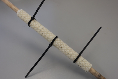
First, mark the template with lines perpendicular to the rod axis on alternating levels. For example, the first line would be on the first row of diamonds (bottom most row of diamonds), and the second line would be on the third row of diamonds, and the next line would be on the fifth row, and so on. Attach the 3-D template to a 1/2" dowel. Use zip ties to constrain the template if needed. Tape one end of the wire (with several inches of slack) to the dowel before braiding. |
|
|
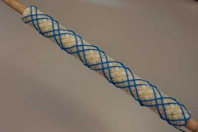
Weave the braid following these rules: 1. The wire will go clockwise around the template (looking at the top of the template) on a braid. 2. The lines drawn on the template will aid the weaving process. Start the weaving process from the bottom of the template, at points where a line is drawn on the template, the wire will always be on top. When going back down, from top to bottom, where a line is drawn, the wire will always be underneath. In this way, the wire travelling in one direction will always be over at the first point, under at the next, over again at the following one and so on. 3. When you reach one end of the template (i.e. the top), the wire should continue clockwise towards the opposite direction (i.e. downwards), following the next available groove/'valley' on the template. Occasionally, the next groove/'valley' is unavailable; in that case, make a tiny loop (circled on the right of the second image) and continue weaving in the same circular direction. |
|
|
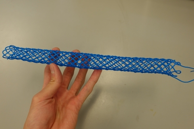
Once the weaving is done, clip the wires with several inches to spare. Then detach the braid ends from the template to remove the braid. |
Assembling the Smart Braid into an Actuator
Once you've woven the Smart Braid, it's time to attach it over the tube and assemble it into an actuator. For this step, you'll need a 30 cm length tubing, gasket maker and super-glue. Also two of each of the following: barbed couplers, tooth-lock washers and hose clamps.
Materials

- Smart Braid
- 30 cm silicone tube (1/4" ID)
- Two barbed tube couplers (1/4")
- Two hose clamps (1/4")
- Two external tooth lock washers (from McMaster)
- Silicone sealant
- Super glue
Assembly
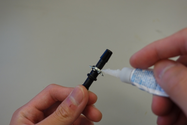 |
Apply super glue to the concave surface of the washers and affix to the barbed tube couplers, teeth facing inward. |
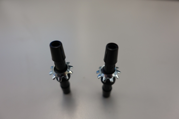 |
Allow the tube couplers to dry upright, with the washers' teeth facing down. Ensure that the washer is as flat as possible (i.e. normal to the coupler axis). Leave the coupler to dry for about a day. |
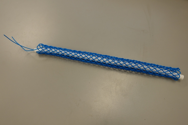 |
Slip the silicone tube through the Smart Braid; its length should fit the braid just right. Fit the tube connectors into the silicone tube with the washer teeth facing outwards, and hook the loops at the end of the Smart Braid to the washer teeth. |
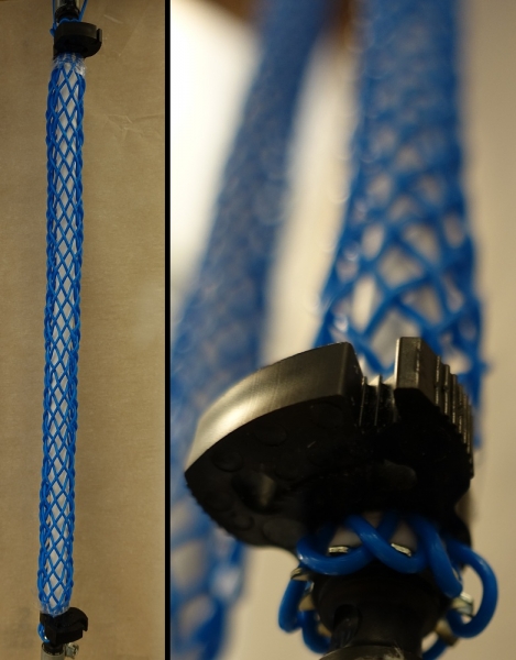 |
Attach the hose clamps afterwards on both ends of the Smart Braid. Optional: wrap some scotch tape around the end of the actuator before attaching the hose clamps to ease the clamping process. |
After the smart braid is assembled, the inductance will need to be measured with a device. Two possible methods have been outlined in the modeling section.
Testing
From Contraction Sensing with Smart Braid McKibben Muscles (2015): "We tested the actuator in a custom-made test apparatus in which we applied different pressures and loads while measuring both inductance and the ground truth actuator contraction. Pressure control was achieved with a custom feedback loop driven by a proportional valve (Enfield LS-V05s) and a pressure transducer (WIKA A-10). Contraction of the actuator was measured from the motion of a sliding carriage affixed to the actuator end. A string potentiometer was used to measure the position of the carriage (UniMeasure LX-PA, 10" range)."
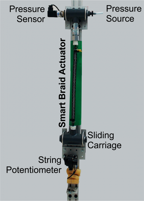
Contraction Sensing
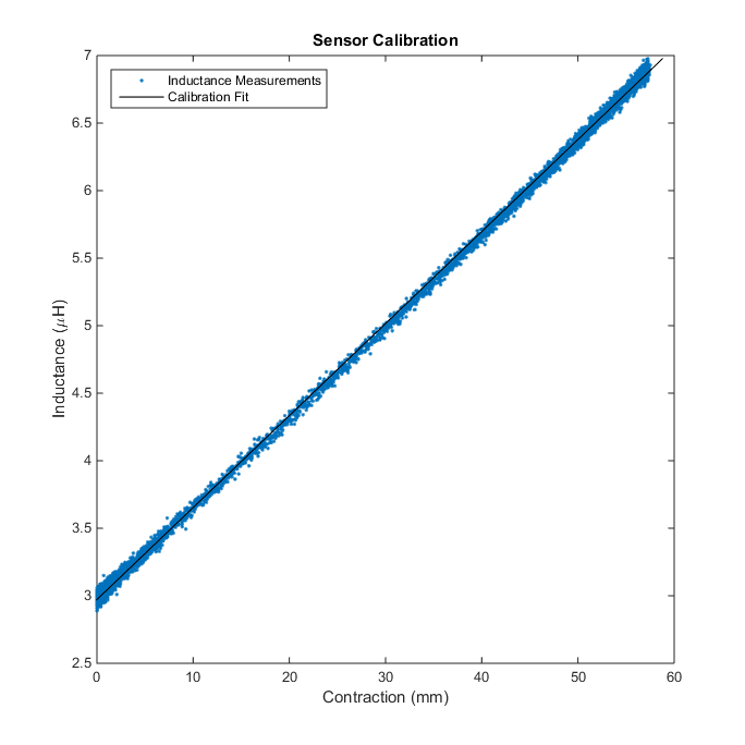
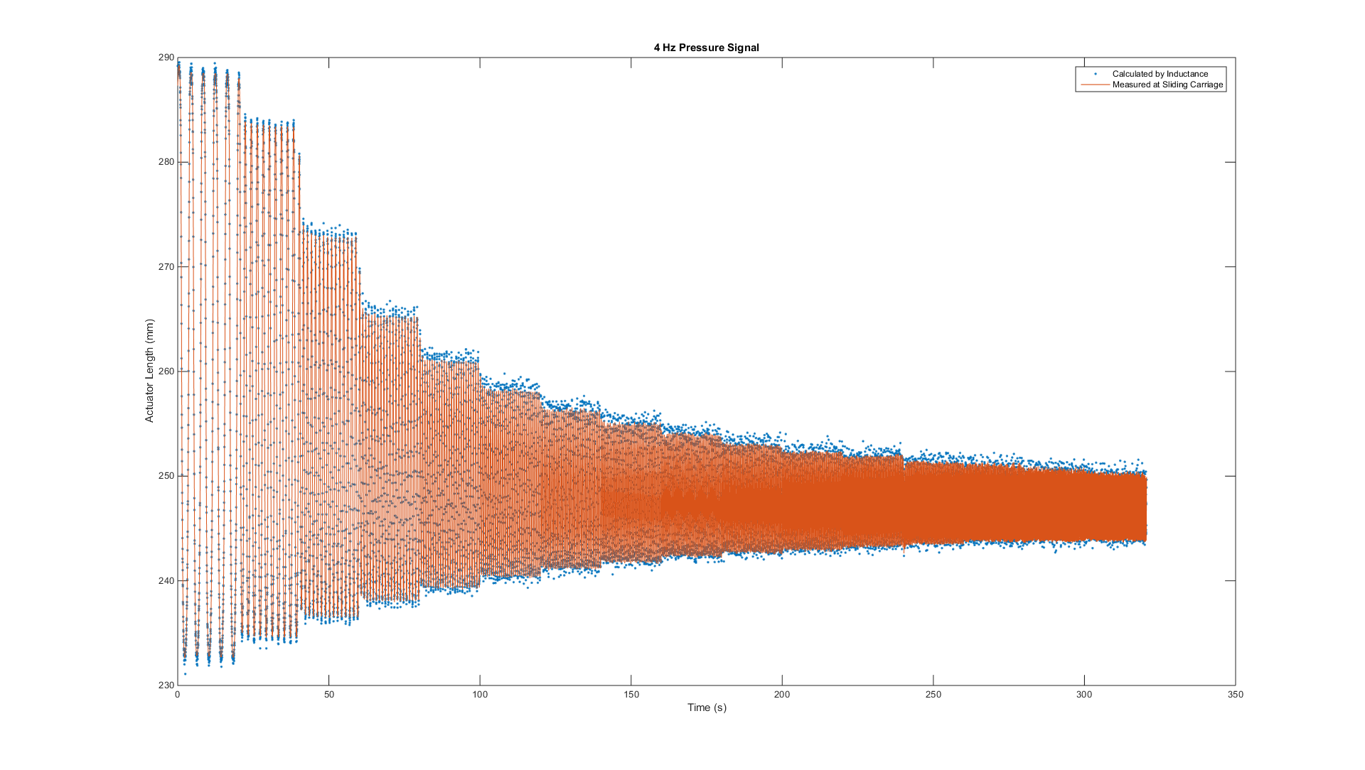
The actuator built with the 30 cm Smart Braid was able to contract 5.7 cm . A linear calibration is sufficient to use the inductance measurements to predict the actuator contraction. The contraction was able to measured within about a milimeter. The sensor response was tested with a sinusoidal pressure signal up to 4 Hz and could not find any evidence of performance degradation.
Force Sensing
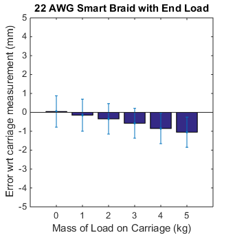
The wires of the 22 AWG Smart Braid were too thick to to have any sensitivity to force. Our pilot work for these devices, however, demonstrated that using thinner wires allows one to characterize the force through resistance (see figure 1). In that work, stretching in the test fixture gave the illusion that the inductance was also sensitive to force. This effect became more clear when we tested the 22 AWG Smart Braid on a stiffer test fixture (see figure 2). The stretching in the fixture causes the length of the actuator measured by the inductance and the length as measured on the fixture to diverge slightly under heavy loads.
Thin wires must be used if one desires to have a system sensitive to force. It may be necessary to increase the total number of wires used to prevent the stress on any one wire from being too great. As one increases the number of thin wires used in the circuit, the resistance also increases. One must use care to ensure that the high resistance does not prevent the inductance from being measured.
Figure 1
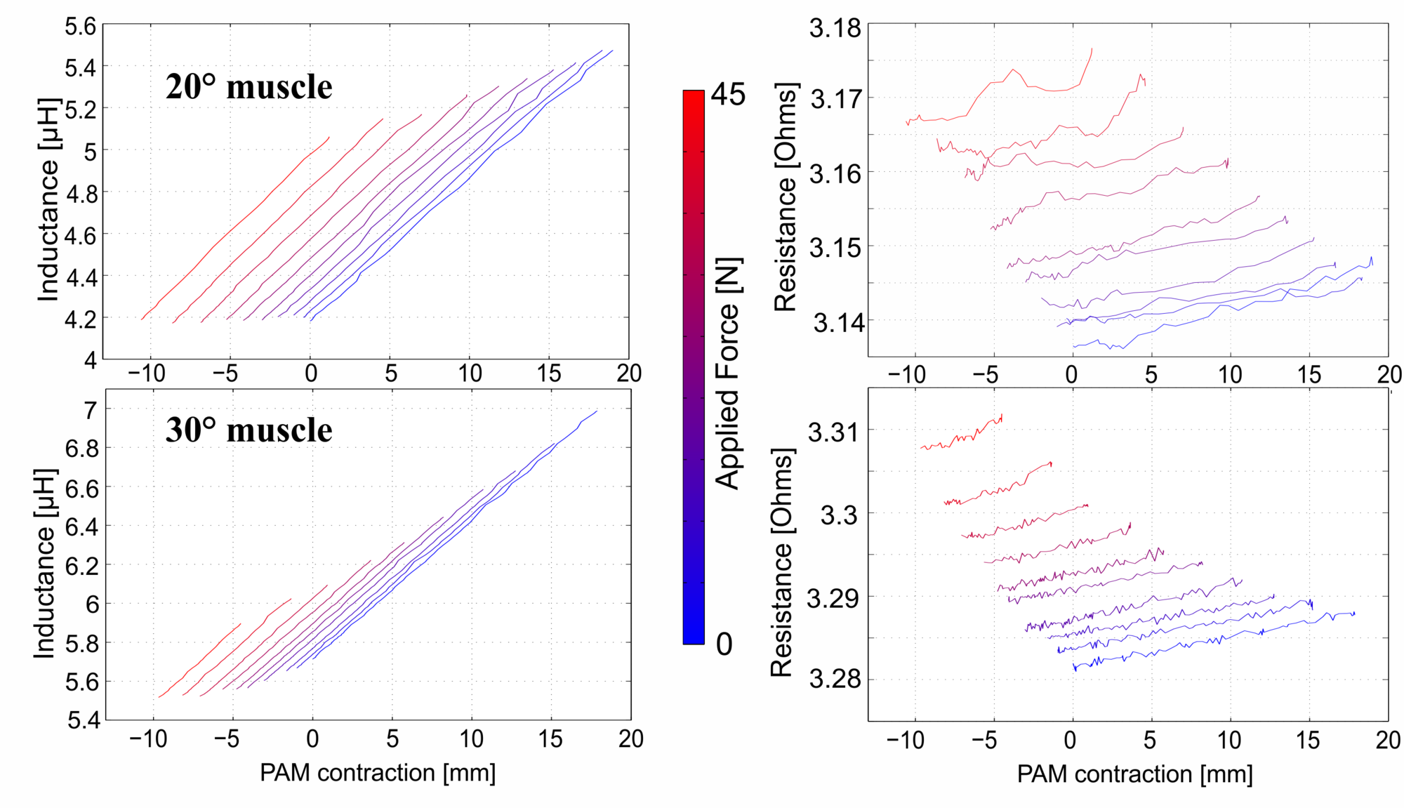
Figure 2
Downloads
| Some of the information contained in this web site includes intellectual property covered by both issued and pending patent applications. It is intended solely for research, educational and scholarly purposes by not-for-profit research organizations. If you have interest in specific technologies for commercial applications, please contact us here. |
| template.zip | 921 KB | |
| smart_braid_design_calculator.xlsx | 12 KB |
