Unleash the Tether: The Development of a Direct Hydraulic Pump-Driven Soft Actuator
 |
 |
In the field of soft robotics, a variety of pneumatic actuators are frequently used in order to achieve softness. The problem is that an external compressor and supply tubes are required to maintain the supply of compressed air. This means that soft robots have to be tethered to external devices and the mobility of robots are limited by those tethers. In designing mobile soft robots, dealing with this problem is an inevitable challenge.
Tolley et al. developed an untethered soft robot using a small commercial air compressor. In this system, two central compressors supply air to all actuators installed on the robot. Each individual actuator is controlled by its own control valve. Small control valves can turn on and off only.
A team of two students (one undergrad, one masters) from Japan designed a solution based on a hydraulic system that can replace pneumatic systems. Since liquid is much less compressible in comparison to gas, it is easy to control actuators more accurately. The difference from conventional hydraulic systems is that the pump directly controls the actuator. The system is compact because it can get rid of complex pipes and control valves. Tethers are not required because the pump can work using batteries. Kaminaga et al. developed EHA(Electro-Hydraulic Actuator)-like actuators which have the same concept, using direct control pumps, for oil hydraulic systems.
In the team's approach, actuators are not solid cylinders but soft actuators such as McKibben actuators and alcohol is used as the working fluid. To achieve this concept, the pump should be specially designed to directly control soft actuators on a tether-less robot.
Design
The design section is divided into two parts, pump and system design, and demonstration design. Before the designs are discussed in detail, we must define the goals of the project and explain the basic mechanism of the system.
The Goal of Project
|
To develop a novel actuation system for tether-less soft robots. Requirements for the system are as follows.
|
 |
Mechanism
 |
Conventional pneumatic systems for soft robotics basically consist of a compressor, control valves, and actuators. To install them in soft mobile robots is difficult because of the size of the compressor. In addition, usual valves can control on and off only. |
Depending on the applications, you can modify the 3D printed outlet casing.
 |
 |

Pump and System Design
Fluid sharing system design

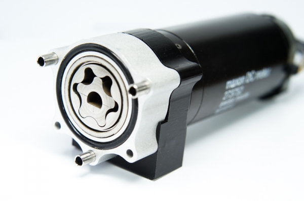
Pump design
The design of the pump is the most important in this project because the performance of the pump decides the performance of the whole actuation system. To control the flow precisely, reducing the internal leaking is required. On the other hand, to reduce gaps between the rotors and casing causes the increasing of the friction between them. In addition, because we use alcohol instead of oil as the working fluid, we cannot expect the lubrication by oil. Moreover, we should consider fabrication methods using affordable materials and parts. At the maximum to reduce the friction without internal leaking, the pump incorporates thin ball bearings and oil-less slide plates.

The basic mechanism was the same as usual rotary pumps but the structure was redesigned to make the pump small and easy to fabricate. The pump also incorporates many commercial parts.

You can download .step file of the pump design (Download CAD data).
Demonstration
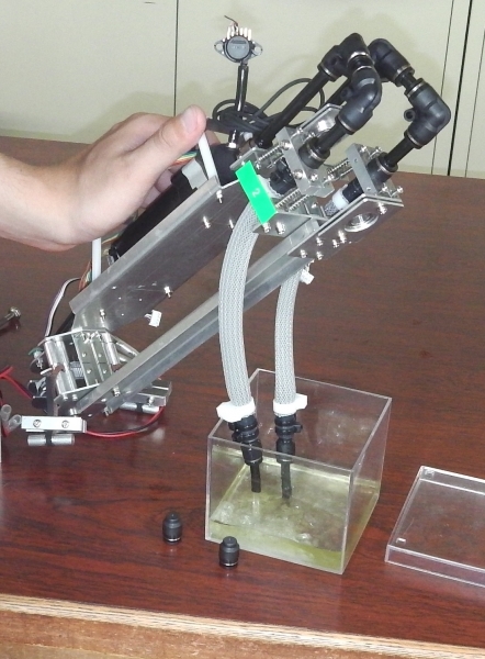
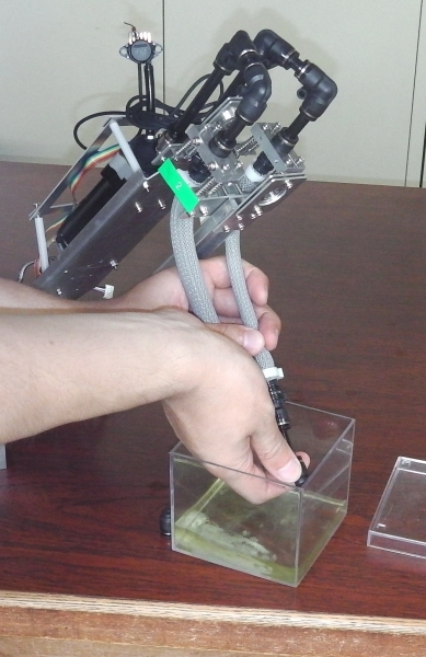
To demonstrate the actuation system, we developed a swing robot as shown below.
OverviewPeople swing by moving their body forwards and backwards. We swing by moving our legs at the right time. We made the robot that reproduces that motion. The robot consists of an arm unit and a body unit. The arm unit connects a fixed joint with bearing (it is referred to as free joint). The body unit connects to the arm unit with a bearing (it is referred to as powered joint). We can control the powered joint with two McKibben actuators. The robot swings by a control powered joint at the right time. The McKibben actuator and pump are in the arm unit. Electric parts are in the body unit. Almost all of the frame parts are made by machining (Download .step file). GoalThe swinging robot needs instantaneous large force when it bends the powered joint. Because of this, the actuator has to be strong enough. The goal of this demonstration is to show that the joint controlled by the actuation system is quick and elastic enough. |
 |
|
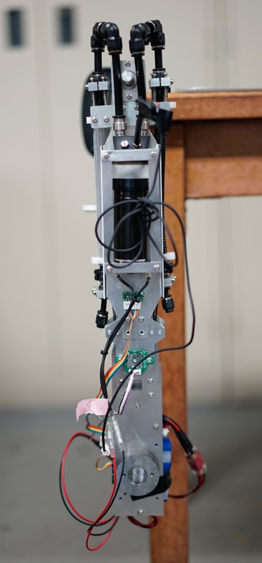
Arm unit |
|


Weight Balance Simulation
To make the robot we considered the opposite ratio of body unit weight to the total weight with simulations. We use VisualC++ and ODE (Open Dynamics Engine). The program control powered joint so as to be bent 60 degrees when the robot is just below free joint, to be straight when the robot is at maximum amplitude of a swing.

We considered the time of gain in swing amplitude from 20 degrees to 60 degrees.
Below is the result of the simulation. Red graph shows acceleration.
The graph below shows the result of the simulation.

The design guidelines that weight radio should be about 40-60%.
The actual arm unit: length 285mm, weight 1.08kg
The actual body unit: length 183mm, weight 0.66kg
--> The actual ratio: 38%
Powered Joint Operation Unit
To operate the powered joint, two McKibben actuators pull a timing belt that fits the powered joint with timing pulley. We put the sensor that measures the angle of the powered joint. Detected angles are fed back to the McKibben control.
The picture below shows the simplified arm unit. A left bearing hole is connected to the free joint. The right shaft is connected to the powered joint.

Belt Tensioner
Since two McKibben actuators are connected to one pump, the sum of the volume of fluid in two Mckibben actuators is constant. This means that the sum of the length of two Mckibben actuators is not constant because Mckibben actuators do not contract linearly. To avoid timing belt from coming off the timing pulley, we made belt tensioners using springs.
 |
 |
Electronic Circuit
The main controller is AVR ATmega168P, which has 16KB program ROM, 512B SRAM, and 22 GPIOs. And it is operated at 8MHz. The team also used mcp3208 (AD converter) and NJU3711D (IO expander).
The main board has interfaces to acceleration, angle, hydraulic pressure sensors and the motor driver.

To acquire the status of the robot, we use LSM303D which can acquire the value of acceleration up to 16g. To drive the pump, we used the dual VNH2SP30 motor driver carrier MD03A, which can drive up to 30A. For the power supply, we used two 7.2V 1300mAh lithium polymer batteries.
|
Main board and motor driver |
Angle sensor and acceleration sensor |


|
XBee WiFi: to connect a PC wirelessly |
Battery |


|
Pressure sensor: MPX5700GP (up to 700kPa) |

Fabrication
This section, divided into the following three parts, introduces a method to fabricate the actuation system.
- Machining and Printing Parts
Introduces some machining methods to make custom parts for the pump - Assembly of the Pump
Introduces the way of assembly of the pump step by step - Assembly of the System
Introduces the way of assembly of McKibben actuators and connecting components.
Bill of Materials
We provide here a BOM for the pump. Most of the parts were purchased through Japanese online stores. You can replace unavailable parts with equivalent parts that you can buy.
Parts
| Parts | Manufacturer's number or specification |
Custom parts |
Material | Qty |
| DC motor | Maxon DC motor 273752 | 1 | ||
| Rotary encoder | CUI AMT103 | 1 | ||
| Oil seal mounting | Milling | POM 7mm | 1 | |
| O-ring | NOK 1A S-20 | 1 | ||
| Oil seal | NOK SC6167 | 1 | ||
| Low profile cap screw | M2.5x6mm | 6 | ||
| Motor mounting | Milling | POM 15mm | 1 | |
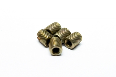
| M2.5 insert screw | Ensat 302 000 025 | 5 | ||
| M3 insert screw | Ensat 302 000 030 | 2 | ||
| Cover side plate | Wire EDM | Oil-less slide plate 2.5mm | 1 | |
| Rotor casing | Milling | Aluminium | 1 | |
| O-ring | NOK 1A S29 | 1 | ||
| Shim ring | Wire EDM | Stainless steel 1mm | 1 | |
| Bottom slide plate | Wire EDM | Oil-less slide plate 2.5mm | 1 | |
| Thin bearing | NMB DDA-2520 | 2 | ||
| Outer rotor | EDM | Stainless steel 9.5mm | 1 | |
| Inner rotor | EDM | Stainless steel 9.5mm | 1 | |
| Stainless steel spacer | Hirosugi CU-2616PH | 3 | ||
| Stainless steel cap screw | M2.5x20mm | 2 | ||
| Outlet casing | 3D printing | Nylon | 1 | |
| Tube fitting (inner hex, straight type) | PISCO POC8-01 | 2 | ||
| Fitting (plug type) | PISCO SLP-M5 | 1 | ||
| Fitting (barb straight type) | PISCO SLC-0640-M5 | 1 | ||
| O-ring | NOK 1A SS-145 | 2 | ||
| Stainless steel cap screw | M2.5x25mm | 3 | ||
| /unit | ||||
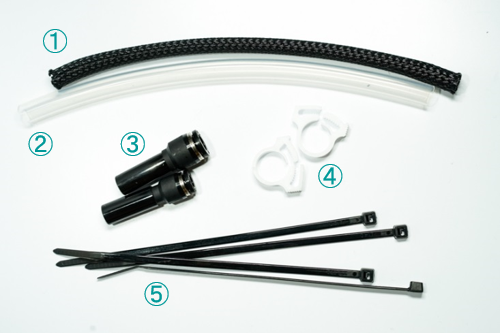
| Braided outer mesh | Lay flat width: 12mm | 1 | ||
| Silicone tube |
Outside diameter: 10mm |
1 | ||
| Tube fittings (Unequal plug-in, straight) | PISCO PGJ10-8 | 1 | ||
| Tube fittings (Unequal plug-in, straight) | PISCO PGJ10-6 | 1 | ||
| Plastic hose clamps | Hellermann Tyton SNP-6 | 2 | ||
| Cable ties | 4 | |||
| Tube fitting (Cap type) | PISCO PPF6 | 1 |
Tools and Consumable
Other than the previous list, the following tools will be needed.
- Silicone oil
- Denatured alcohol
- M5 tap
- Rc 1/8 (short type) tap
Machines
- CNC milling machine
- Wire EDM
Machining and Printing Parts
Some customized parts need to be fabricated in order to make a pump. The design requires three techniques of lab-level fabrication, CNC machining, 3D printing and wire Electrical Discharge Machining (EDM).
CNC Machining
POM
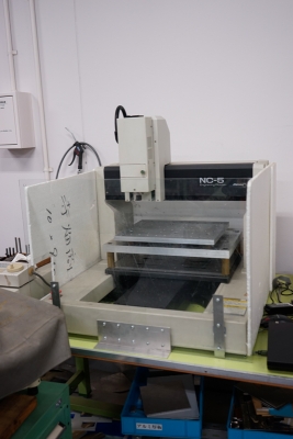
POM is an engineering plastic used in a wide range of industries. Machining this material is very easy and the material has enough strength. The team used a CNC milling machine to make some parts.
|
POM plates |
CNC milling machine we used (Mimaki NC-5) |

In the design of the pump, CNC machining was used to make following two parts .(Download CAD data)
 |
Oil Seal CasingPOM plate (Thickness: 7mm) |
 |
Motor MountingPOM plate (Thickness: 15mm) Install five M2.5 insert screws (Ensat 302 000 025) on the side and two M3 insert screws (Ensat 302 000 030) on the bottom
|
Aluminum
The team used the fabrication service because machining power is required compared to POM parts. (Download CAD data)
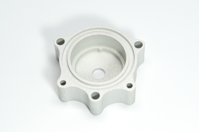 |
Rotor CasingAluminum A5052 Finish: sand blast |
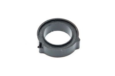
3D printing
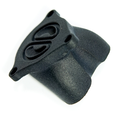 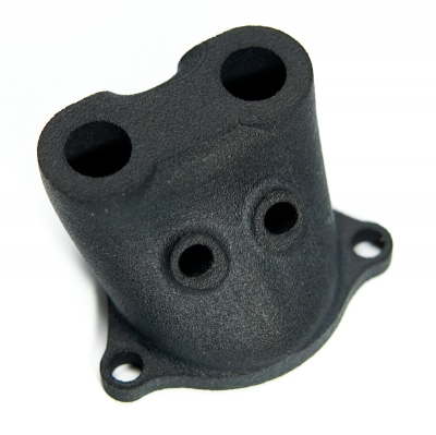 |
Outlet CasingNylon 3D print The surface is colored with black dye. |
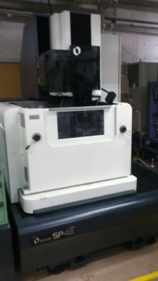
Wire EDM
|
We used wire EDM for high precision machining of stainless steel and slide plates because wire EDM can cut the metal even if it is really hard. (Download CAD data) |
Wire EDM we used (Makino SP43) |
Stainless steel
Stainless steel is suitable as a material of rotors. However, stainless steel is a difficult material for CNC machining. Precise machining is also required for rotors. Wire EDM is one of the best choices for rotor machining.
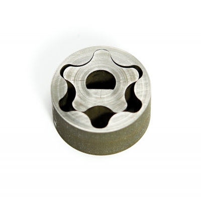 |
Out rotor and inner rotorStainless steel SUS303 plate (Thickness: 9.5mm) |
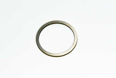 |
Shim ringStainless steel plate (Thickness: 1mm) |
Oil-less Slide Plate (DAIDYNE DDK05)
To reduce the friction between rotors and casing, we set oil-less slide plates both sides of the rotors.
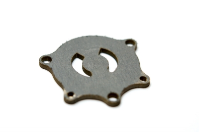 |
Cover slide plateDAIDYNE DDK05 slide plate (Thickness: 2.5mm) |
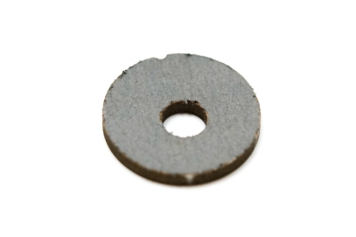 |
Bottom slide plateDAIDYNE DDK05 slide plate (Thickness: 2.5mm) |
Assembly of the Pump

A key component of this system is a specially designed rotary pump. Though the pump is designed with the concept of easy fabrication, sometimes you have to pay attention to the assembly of some parts. Be careful, for accuracy of this assembly may affect the performance of the pump.
Step1: Prepare a Motor
The team used a Maxon 273752 DC motor (15V 90W). You can make smaller pumps using small motors if you find a good way to seal a small diameter shaft.

 |
You need to file a flat surface on the tip of the shaft. |
 |
If you need a rotary encoder, attach the other side of the main output shaft. We installed a CUI AMT103. |
Step2: Assemble the Motor Mount and Shaft Sealing

Parts List and Assembly
 |
|
 |
Motor mounting with insert screws |
 |
Attach the mounting on the motor. |
 |
You need a wrench to fit the cap screws. |
 |
Use a wrench, tighten cap screws. |
 |
|
 |
Use an oil seal (Outer:16mm Inner:7mm). |
 |
Oil seal mounting |
 |
Push the oil seal into the hole of the mounting. |
 |
Oil seal should be inserted all the way down into the hole. |
 |
Install an O-ring. |
 |
Spread silicone oil on the shaft. |
 |
Spread silicone oil also on the lip of the oil seal. |
 |
Insert the oil seal mounting into the hole of the motor mounting. |
 |
The seal mounting would be tightly fitted to the hole. |
Step3: Assemble a pump box

Parts List and Assembly
 |
|
 |
Outer rotor and inner rotor were machined by a wire EDM. |
 |
Using a jeweler's file, smooth down the burrs on the side. |
 |
|
 |
|
 |
Using sandpaper (#400), sand the surface until smooth. |
 |
Using the jeweler's file, smooth down the burrs on the side. |
 |
Using the jeweler's file, smooth down the burrs on the side as well. |
 |
Using sandpaper (#180 and #400), sand the surface until smooth. |
 |
|
 |
Using sandpaper (#180 and #400), sand the surface until smooth. |
 |
|
 |
Using a router bit, remove any burrs from the center hole. |
 |
Using sandpaper (#180 and #400), sand the surface of the inside until smooth. |
 |
|
 |
Place the slide plate into the pump casing. |
 |
|
 |
Place the first bearing into the pump casing. |
 |
Push the bearing down carefully all the way making sure it is straight. |
 |
Place the second bearing into the pump casing. |
 |
Push the bearing down until it touches the first bearing. |
 |
Place the outer rotor into the bearings. |
 |
Make sure that the outer rotor touches the surface of the bottom slide plate. |
 |
Place a shim ring. |
 |
Place an O-ring. |
 |
|
 |
Push the casing into the motor mounting until it touches the surface of the mounting. |
 |
|
 |
Insert the inner rotor into the outer rotor and D shaped shaft. |
 |
Step4: Assemble the outlet casing

Parts list and Assembly
 |
Use three stainless steel spacers (Hirosugi CU-2616PH Outer:3.8mm Inner:2.8mm). |
 |
Install spacers. |
 |
Put the cover slide plate on the casing. |
 |
Tighten stainless steel cap screws (M2.5x20mm). |
 |
3D printed outlet casing |
 |
To make a flat on the mounting surface, sand the surface until smooth. |
 |
Remove dust. |
 |
|
 |
You need two kinds of taps, M5 and Rc 1/8 (short type). |
 |
Tap the two small holes with a M5 tap making sure it is straight. |
 |
Tap the two big holes with a Rc1/8 tap making sure it is straight. |
 |
|
 |
|
 |
Install the straight type fitting. |
 |
Install the plug on the other one. |
 |
Using a large wrench, tighten the fittings. |
 |
Place o-rings. |
 |
Put the outlet casing onto the rotor casing. Tighten with three screws (M2.5x25mm). |
 |
|
Assembly of the System
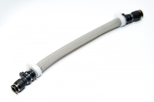
Step1: Assemble McKibben actuators
As you know, the McKibben actuator is one of the most common traditional soft actuators. There are a lot of ways to make this actuator. The method we will introduce here is simple and useful to assemble using cheap commercial parts.

Parts list and Assembly
 |
List
|
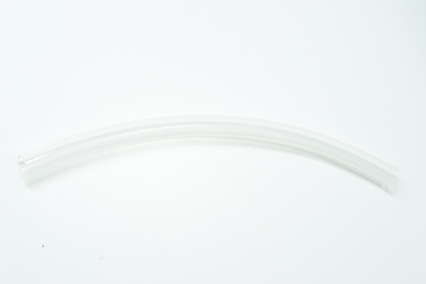 |
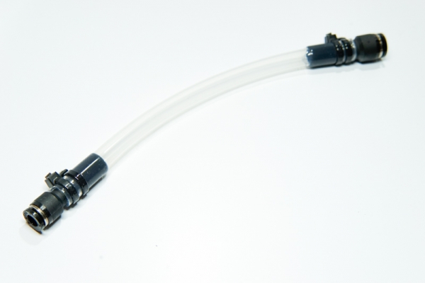
Cut the silicone tube down to 190mm Note: please adjust the length to fit your purpose. |
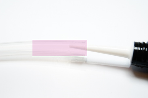 |
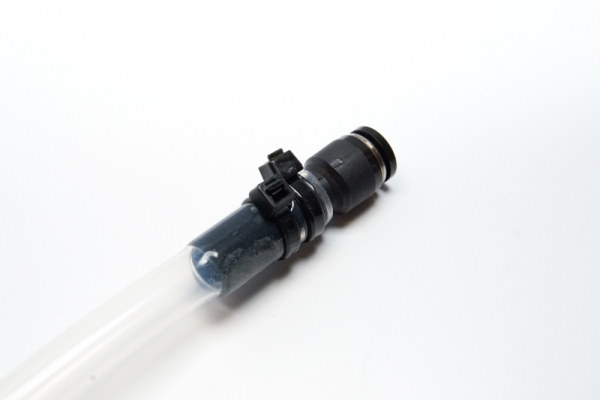
Spread the silicone oil inside the tube (highlighted area). |
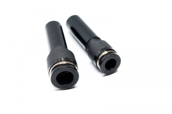 |
Φ8 and Φ6 tube fittings (unequal plug-in, straight type) |
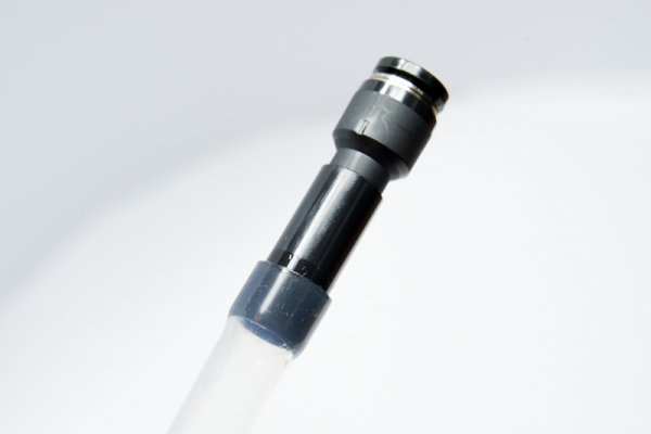 |
Carefully, insert the pipe of the tube fitting into the silicone tube. |
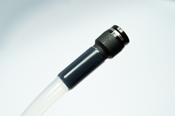 |
Insert the tube fitting all the way down into the silicone tube. |
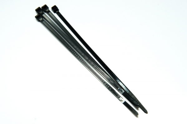 |
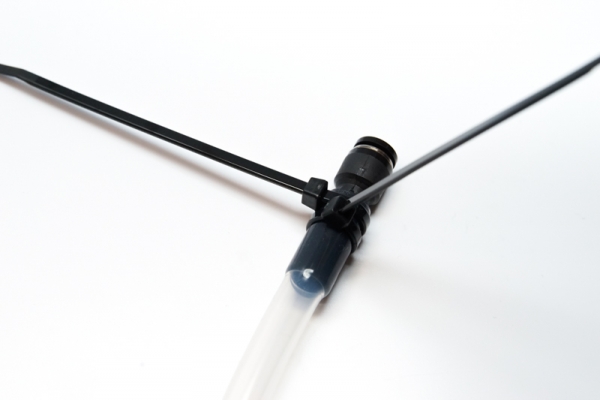
Four cable ties |
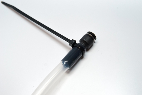 |
Tighten the cable tie around the silicone tube. |
 |
The second one is as well. |
 |
Cut the extra tie off. |
 |
Do the same on the other side. |
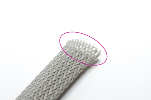 |
Cut the braided outer mesh down to 190mm. |
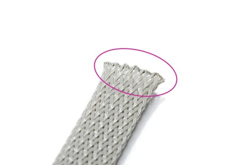 |
To prevent the mesh from getting frayed, melt the end of the strands using a flame. |
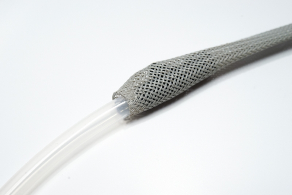 |
Put the silicone tube into the mesh. |
 |
The tube should fit all the way into the mesh. |
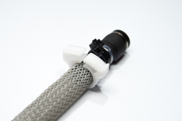 |
Tighten a plastic clamp around the end of the mesh. |
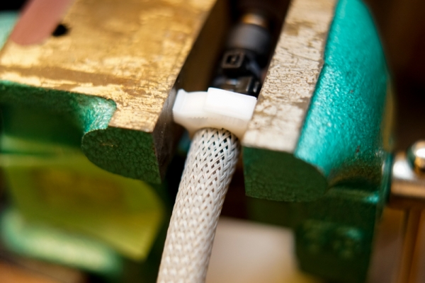 |
Using a vise, you need to fully close the clamp. |
 |
Clamp the other side in the same way. |
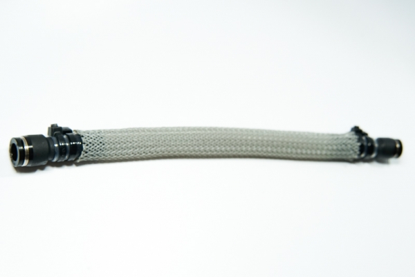
Step2: Connect the pump and McKibben actuators
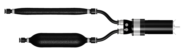
Connect McKibben actuators and the pump using polyurethane tubing (outer: 8mm inner: 6mm). Cap the end of McKibben actuators using cap tube fitting (PISCO PPF6).
Step3: Fill the actuators with alcohol
You need to prepare denatured alcohol in a bucket.
 |
Start the pump and circulate alcohol to remove air. |
 |
Cap the outlet with the cap tube fitting. |
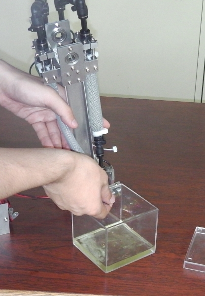 |
The capped side Mckibben actuator will be inflated. Then, cap the other side. |
Testing
|
This section describes the results of the testings. To verify the performance of the prototype system, a few experiments were pursued. First of all, basic performances of the pump and McKibben actuators were measured. Second, installing the system in the swing robot, it was confirmed that the design worked as intended. Finally, the swing robot was operational. Back to the goal of the project, the team accomplished building a tether-less hydraulic system using alcohol as the working fluid. The results of performance tests suggest that the flow inside of the actuation system is powerful and controllable accurately. Though the prototype is small enough to install in the swing robot, there remains room for improvement in terms of the size. It is significant that we can introduce this method to make tether-less hydraulic systems using basic prototyping tools. Original goals
|
 |
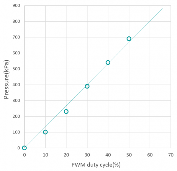
Basic Performance
The prototype of the pump and McKibben actuators were tested, and each graph shows the results.
Condition: No load
Power source: 4-cell lithium polymer battery (14.8V)
PWM duty cycle - Pressure Rate
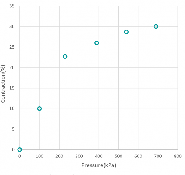
Pressure - Contraction Rate
Control Test
Test Operation
The video below shows the motion of a pair of McKibben actuators.
Testing of the Belt Tensioner
The belt tensioner avoids slack of the timing belt. The mechanism works properly.
PID Control
The team programmed a micro controller for the experiment of PID control to the powered shaft with no load. The PID control is be described below.
|
Rpwm |
Rate of pwm (0.0~1.0) |
|
y(t) |
Difference between target value and sensed value (unit :degree) |
|
kp,ki,kd |
PID control parameters |
![]()
Parameters used this time are:
kp: 0.027, ki: 0.0013, kd: 0.0013
The following graph shows the result of a tracking test. Although there were some overshoots, angle sensor values tracked the reference signal with good responsiveness.

Swinging Test
Finally, the swinging robot driven by the actuator (timing was manually controlled) was tested. Maximum amplitude was approximately 35 degrees. The demonstration showed that the joint of the actuation system rotated quickly and it was elastic (not stiff).