A Synergistic Design Leveraging the Diverse Functionalities of Soft- and Rigid-Bodied Robots
Soft robots offer the versatility to accomplish a number of basic functions, including moving in tight spaces, climbing walls, and grasping items. This versatility comes naturally through actuation mechanisms that provide large forces and displacements in highly compliant packages. In their current state of development, the majority of the freedom in soft-bodied robot design is achieved when their support equipment (pneumatic cylinders, air valves, computational hardware) is kept off-board from the soft robot. Unfortunately, fixturing this support equipment can severely limit the achievable range of motion needed for useful, real-world tasks. Rigid-bodied mobile robots, on the other hand, are capable of carrying heavy loads and quick, robust movement in wide-open areas. When it comes to tasks such as manipulation or inspection in cluttered environments, collision avoidance is often necessary and situations may be encountered where it is not possible to execute such motions. Soft robots offer a viable alternative, since they can move in cluttered environments without needing to remain free of collisions. The synergistic integration of soft- and rigid-bodied robots into a hybrid system offers a unique solution to fulfilling tasks in real-world environments: a robot that may operate effectively in open areas, yet also be able to navigate challenging areas of the workspace. Motivated with this aim, our team has integrated a soft-bodied “minion” bot with a KUKA youBot for an autonomous retrieval task. The youBot is able to transport the soft robot and its support equipment in easy-to-navigate areas of an environment. In more challenging areas, a soft robot may be deployed to retrieve objects. With the extesible hardware resources of the youBot, it is possible to coordinate the two robots in order to fulfill the goals that either platform alone would not be able to achieve. This advancement in robotic symbiosis will broaden the horizon for practical applications of soft-bodied robots in completing desired tasks.
The Team
L to R: Prof. Hadas Kress-Gazit, Prof. Robert Shepherd, Lauren Ransohoff, Corinne Lippe, Jonathan DeCastro, Eric Simeonoglou, Victor Dorobantu
Victor Dorobantu, Sophomore Computer Science student at Cornell University, minoring in Mechanical Engineering and Electrical and Computer Engineering. Role: Pneumatic and electrical system design and algorithm development for soft robot control.
Corinne Lippe, Junior Mechanical Engineering student at Cornell University. Role: Implementation and testing of the youBot manipulator software.
Lauren Ransohoff, Junior Mechanical Engineering student minoring in Computer Science. Role: Camera-based localization, controller implementation, and overall integration.
Eric Simeonoglou, Senior Mechanical Engineering student at Cornell University. Role: Design and fabrication of the physical soft-bodied robot.
Jonathan DeCastro, Ph.D. Student in Mechanical Engineering at Cornell University. Role: Mentoring and technical advising for the development effort; ROS support.
Prof. Hadas Kress-Gazit, Mechanical and Aerospace Engineering at Cornell University. Role: Faculty co-advisor.
Prof. Robert Shepherd, Mechanical and Aerospace Engineering at Cornell University. Role: Faculty co-advisor.
Background
Soft robots are capable of executing a variety of functions in low-cost, lightweight, and mechanically-compliant packages. As such, they could be capable of functioning in challenging environments involving uneven terrain, obstacles, and fitting within small spaces. Equipped with sensors, they may be able to assist in search-and-rescue operations in a disaster area, or retrieval of objects in spaces that are too confined or hazardous for humans or large robots to negotiate. Morin, et. al., 2012 even demonstrated the capability of soft robots to camouflage themselves in order "disappear" from the view of adversaries.
Small agile robots such as the iRobot Packbot, the Boston Dynamics RHex, and the Stanford microTugs are capable of motion in challenging environments, but due to their rigid nature cannot conform to a surface or object and are generally limited in their ability to with manipulation in small packages. Furthermore, they are typically more challenging to fabricate, limiting the possibility to deploy fleets of similar robots. Recently, Paik, Cho and Kim, 2015 have devised a soft-bodied micro robot that can gently lasso an ant in a package that is only twice the diameter of a human hair.
In keeping with the design requirement for a small soft robot design, we develop a hybrid robot where the computing hardware and pneumatic pressure system supporting the soft robot are combined with a rigid-bodied robot - a KUKA youBot. This hybrid system is shown below. This hybrid soft/rigid robot is advantageous over any one of these systems in isolation for several reasons:
- Improved mobility. A mobile rigid base is able to shuttle the soft robot quickly between points in the workspace that are less challenging to maneuver, allowing the soft robot to traverse areas that are unreachable for the rigid-bodied robot.
- Improved self awareness. The rigid platform can provide exteroceptive sensing capability (i.e. an RGB+D camera) for accurate localization, enabling a high degree of success in achieving tasks.
- Synergistic functionality. The computing resources of the youBot are powerful enough to enable coordination between the two robots for accomplishing a richer set of tasks (e.g. autonomous manipulation of objects) than either platform can perform in isolation.
- Extensibility. A rigid-bodied robot can provide a platform that can be interchanged with different soft robots or expanded to deploy several soft robots at once, providing a platform that is versatile enough to handle a wide variety of tasks.
Hybrid soft and hard robots have been explored recently as a viable design alternative to completion of search-and-rescue missions. In particular, our work is inspired by that of Stokes, et. al. 2014, in which the authors developed a hybrid robot set out to perform an object retrieval task. A soft robot design was combined with an iRobot Create robot as the rigid base to demonstrate the synergistic benefits of a hybrid soft and rigid-bodied design. In that work, there was no automation in the control of the two robots, as the two robots were independently teleoperated by a user, although many synergistic benefits were deonstrated.
The aim of our team's hybrid soft/rigid robotic system is to demonstrate synergistic benefits directly by creating a fully autonomous object retrieval task, through the use of a high-level controller that provides commands to the soft robot through the use of a controller developed in the Robot Operating System (ROS) environment. To accomplish this, we choose a rigid-body robot (youBot) with computational resources powerful enough to coordinate the two robots, features a manipulator to enhance the synergism between the robots, and is large enough to be extensible to various types and larger numbers of soft robots. We also evaluate various soft robots for effectiveness in locomotion and object grasping, and develop controllers for each. Lastly, we demonstrate vision-based navigation with our chosen soft robot design by making use of a camera mounted on-board the youBot to track both the object to be retrieved and the soft robot in real time. To our team's best knowledge, this is the first attempt at soft robot autonomy for a hybrid rigid-bodied and soft robot design.
Stephen A. Morin, Robert F. Shepherd, Sen Wai Kwok, Adam A. Stokes, Alex Nemiroski, George M. Whitesides, "Camouflage and Display for Soft Machines." Science, Vol. 337 no. 6096 pp. 828-832.
Jungwook Paek, Inho Cho, and Jaeyoun Kim, "Microrobotic tentacles with spiral bending capability based on shape-engineered elastomeric microtubes." Scientific Reports, Vol. 5, 10768, 2015.
Adam A. Stokes, Robert F. Shepherd, Stephen A. Morin, Filip Ilievski, and George M. Whitesides, "A Hybrid Combining Hard and Soft Robots." Soft Robotics, Vol. 1, no. 1, 2014.
The soft robot, deployed from the youBot, grasping a "minion" in an autonomous object retrieval task.
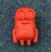
The target object: A Minion.
Design
Object Retrieval Scenario
As a goal for demonstrating a working system, the team devised an example object retrieval scenario, described below. This scenario served to solidify the required functionality for the robot.
|
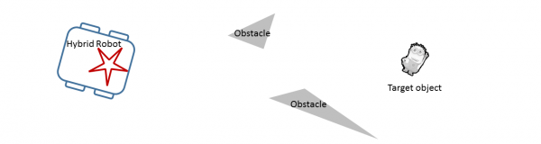
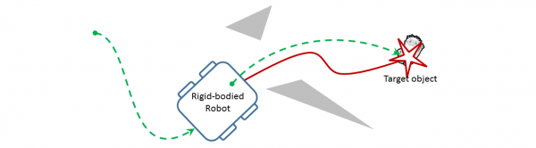
1) The hybrid robot (combination of rigid-bodied and soft robots) moves toward the target object (minion), which cannot be reached by the rigid-bodied robot due to obstacles. |
 |
|
2) The rigid-bodied robot stops, then deploys the soft robot (red). The soft robot moves toward the object and grasps it once there. |
 |
|
3) The soft robot, grasping the minion, returns to the rigid robot, and both are retrieved. |
 |
Design Criteria - Rigid-Body Robot
The design for the rigid platform is largely constrained by our ambitious task of demonstrating autonomous object retrieval. We require the robot to have size large enough to house and power all elements of a soft robot, specifically, the air manifold, valves, Arduino controller, and the soft robot itself. We also necessitate a vision system capable of tracking the location of the soft robot in 3D space. Next, we require the computational resources necessary to implement the object retrieval task in real time and integrate the functionality of both types of robots on a single host computer. One of the attractive features of soft robots is their cost effectiveness and portability. We lastly aim to extend these benefits to the hybrid robot, by keeping the hardware at a reasonable cost in a package that is relatively small and lightweight.
Design Criteria - Soft Robot
The soft robot is required to move anywhere in a planar environment bounded only by its support tether in a potentially cluttered space. Specifically, the robot is required to move in a circular domain with radius of at least 1 meter, and was required to climb over small objects and grasp a small item (both ball shapes of at least 1-inch diameter).
The Rigid-Bodied Robot
Comparison of Rigid-Bodied Candidate Robots
We require an autonomous mobile robot platform that provides plenty of room to place the pressurized system to control the soft robot. The table below briefly compares the hardware specifications of both the KUKA youBot and a customized iRobot Create (similar to the rigid platform in Stokes, et. al., 2014). Based on this comparison, the youBot holds more potential than the Create with respect to many of the stated design criteria: ease of software development, sensor capability, mobility, ability to manipulate, and extensibility. We therefore choose the youBot at the sacrifice of two categories - size and cost - which is justified since the size and cost is still competitive with many customizable, sensor-rich and commercially-available autonomous robots available on today's market.
| Robot Type | iRobot Create with BeagleBoard onboard computer | KUKA youBot with single arm |
| On-board Computer | beagleboard-xM, AM37x 1GHz ARM processor, 512 MB RAM | Mini-ITX, Intel Atom D510 Dual Core 1.66 GHz, 2GB RAM, 32 GB SSD |
| Operating System | Linux | Linux |
| ROS Support | Limited | Good |
| Base Type | Two-wheel differential drive (nonholonomic drive) | Four omnidirectional wheels (holonomic drive) |
| Manipulator | None | 5 DOF arm with 2-finger gripper |
| Sensor Capability | Webcam, sonar | Extensible - RGB+D camera, LIDAR |
| Dimensions | 33.8 cm diameter x 8.8 cm height | 58 cm x 38 cm x 14 cm |
| Cost | ~$200 | ~$20K |
The KUKA youBot (pictured below) consists of an omnidirectional platform, with a five degree-of-freedom manipulator with a two-finger gripper. The arm is an attractive feature, because it allows a way for the soft robot to be deployed from a convenient location atop the robot, and also allows the soft robot to be retrieved once it grasps the object of interest. Our youBot is also equipped with an ASUS Xtion Pro RGB+D (color image + depth image) camera similar to the Microsoft Kinect. The youBot is provided with open interfaces and includes ROS and comes pre-configured with controller drivers. The wheels are omnidirectional, allowing the robot to move freely in any direction with any orientation.

image source: http://www.kuka-labs.com/
The Soft Robot
|
The soft robot design cycle followed a "spiral development" process, with a design that evolved according to the needs of the system as a whole and limitations uncovered during testing. As such, our design followed a natural progression, where the existing functions would be assessed and new features would be included at each increment in the spiral. The picture to the right exemplifies the development process for our project. Starfish Robot DesignsVarious configurations of channels and legs of the soft robot allowed for different choices in actuation sequences. Testing began with two versions of a five-legged design. The design pictured below consists of five independently-actuated air channels and a small rib size. This design was compared against with a similar five-legged design with thicker rib size, but testing revealed that this design was more fragile and more prone to rupture. |
Top to bottom: progression of the soft robot designs tested, including variations developed for our application. |

For most preliminary five-legged designs, a sequence of inflating back legs, inflating front legs, deflating back legs, and deflating front legs resulted in an undulating gait when deflate times were allowed to be longer than inflate times. By inflating sharply and deflating slowly, the contact points between the legs and the ground moved forward quickly but did not move back, moving the center of mass of the robot in a controllable direction. However, the resulting movement was slow, since the center of the robot was always in contact with the ground. This constraint also meant that the five-legged design could not raise itself above an object to grasp.

Additionally, keeping one leg permanently deflated (acting as a pivot) and inflating the remaining legs in sequence resulted in a turning gait. However, the angle change was minimal, once again due to most of the soft robot remaining in contact with the ground.
Quadruped Robot Designs
To mitigate the aforementioned issues with the five-legged design, four-legged designs were adopted. Each leg contained two air channels, allowing a paddling motion for each leg to be developed. This was achieved by inflating the back channel (pushing the leg down and forward), inflating the front channel (pushing the leg further down and back), deflating the back channel (pulling the leg up and back), and deflating the front channel (pulling the leg up and forward). By actuating diametrically opposed legs synchronously, interleaving actuation sequences of opposing pairs of legs, and, once again, allowing deflate times to be longer than inflate times, the soft robot was able to move along one of its axes of symmetry.
The quadruped is pictured below, along with a diagram showing the internal structure. For our project, the conceptual design and dimensions in the diagram were used in our design. In our design, we require a place for the manipulator to grasp the soft robot. Our initial design features a silicone tab attached to the top of the soft robot. This tab is visible in the picture below. Other differences are explained in the Fabrication section.
 |
Diagram of the quadruped design, Stokes, et. al. 2014. |

Designing for Manipulation and Vision-Based Tracking
Because the silicone tab did not stand upright, a 3-D printed tab was designed instead and mounted to the soft robot, as shown below. The tab was colored yellow and the soft robot was given the same color in order to produce a ensure that the youBot's perception system can reliably track the soft robot when placed at a reasonable distance away from the youBot and and be robust to changes in the soft robot's orientation.

After testing the soft robot, it was concluded that the yellow tab alone was sufficient to track the soft robot's location using the vision system. Emphasis was placed on coloring the robot such that its orientation with respect to the youBot in any of the four cardinal direction is easily distinguishable. That way, the youBot can provide appropriate commands to move the quadruped toward its goal without resorting to a "guess-and-check" type of control strategy.
The design concept operates on the same principle as a binary color encoder with resolution down to the nearest quadrant. We describe its operation through an example. Assuming the two black legs represent the front of the robot, if a black leg is visible to the left and a white leg to the right in the camera image, then we know the front of the robot is facing left in the camera image. Now, assuming that we want the soft robot to move left in the camera image, it is required to actuate a gait to move the robot forward. By color coding the robot in this way, the control system is robust to variations in how the soft robot is oriented when placed on the ground.
To prevent leaks and having the tubes from being damaged or removed when the youBot manipulator picked up the soft robot, the piping was glued into the soft robot. Because this interfered with the plastic tab, yellow tape was instead used to secure the tubing. The tape served three purposes: to keep the tubing from separating, to act as a handle for the manipulator to pick up the robot, and to act as a color "blob" that could be seen by the youBot vision system.
The tether length was an important factor in the design; the considerations were range of motion, potential for entanglement with the youBot manipulator and wheels, effect of the tether's drag on quadruped mobility, and dynamic range of the vision sensor used for tracking the soft robot.
The published range of the depth readings for the ASUS Xtion Pro camera is between 80 cm and 350 cm. Because the manifold was situated toward the rear of the youBot, 50 cm was added to the required forward travel of the soft robot beyond the front of the youBot. To satisfy the camera constraints, a tether length between 120 cm and 400 cm was required. We ultimately chose 150 cm as the tether length, as this satisfied having reasonable mobility within the field of view of the sensor (between zero and 100 cm from the front of the robot), while keeping the effect of drag small and risk of entanglement low.
Task-Level Control of Soft- and Rigid-Body Robot Behaviors
Camera Integration
The ASUS Xtion Pro camera was used for tracking the soft robot and the target object to be retrieved. It provides both RGB and depth data. As pictured below, the camera was mounted on the front of the youBot. The camera could also be mounted on the wrist of the arm, but since the object and soft robot will always remain at ground level, the front mount was chosen.

The ROS OpenNI package was used to launch the camera driver and access camera data. The ROS package Cmvision was also used to aid with blob color detection in order to locate the red object and the yellow tag on the soft robot in the camera frame. In order to detect the blobs, the following procedure was used.
1. Launch the OpenNI camera driver: roslaunch openni_launch openni.launch
2. Run the Cmvision blob detector color tool: rosrun cmvision colorgui image:=<image topic>
3. Click on the blob you would like to detect until the RBG and YUV color values are given by the GUI.
4. Edit the colors.txt file to include the YUV color of the blob to detect.
5. Launch the Cmvision blob detector: roslaunch cmvision cmvision.launch. A GUI that looks like the image below should appear, outlining the blobs detected with a box. The image below depicts the red object being detected.

More information on the OpenNI and Cmvision packages can be found by viewing their ROS wiki pages:
Vision-Based Soft Robot Navigation
Once the youBot deployed the soft robot, the youBot communicated with the Arduino via a serial communication. A state machine on the Arduino processed incoming commands and executed corresponding actuation sequences for the soft robot. The camera data was used to generate a reference signal based on the position of the target and an error signal based on the position of the soft robot, which were then used to decide which commands to send to the soft robot next. The simple control logic is given below. Here "position" and "reference" are, respectively, the 2D positions of the soft robot and target object in camera coordinates, and "threshold" is a threshold of 20 pixels in the image.
if position < reference - threshold:
execute "move right" gait for 1 sec
else if position > reference - threshold:
execute "move left" gait for 1 sec
else:
execute "move forward" gait for 1 sec
The code for controlling each of the gaits is discussed in the testing section of our wiki.
Task-Level State Machine
To execute the object retrieval task and coordinate the motion of the youBot and soft robot, a state machine was designed. This was done using the ROS Smach (state machine) package. A diagram summarizing the states as well as a brief description of all states is provided below.

Description of states:
Search: The Search state is the initial state of the machine. In this state, the youBot turns clockwise, looking for the object. Once the "/blobs" topic from the Cmvision package returns that it has found a red blob, the youBot rotates to face the blob. It then accesses the depth data of the blob and the state calculates the blob's coordinates in the global coordinate system. Once this has occurred, the Search state exits on "found" and transfers the coordinates of the blob to the next state.
Drive: The transition "found" goes to the Drive state. In this state, the youBot uses the coordinates of the blob from the Search state and drives to those coordinates. The youBot actually drives to 20 cm away from the coordinates in order to give the arm and soft robot room to reach the object. Once the youBot is at the proper coordinates, the state machine returns "here", which brings it to the next state.
Dropoff: The next state is Dropoff. In this state, the arm picks up the soft robot from the back of the youBot and drops it off slightly to the right in from of the youBot. Once the soft robot is dropped off, the state returns "deployed" and transitions to the next state.
Wait: The next state is Wait. This is where the youBot stays still, but sends commands to the Arduino for the soft robot. Additionally, the blob detection is run in this state, and the youBot tells the soft robot to move right or left depending on its relative position to the blob (comparing the yellow and red blobs). Once the soft robot gets to the object, the state returns "reached".
Return: "Reached" brings the state machine to to the final state: Return. This brings the arm back to its original position and once the arm is there outputs "done". "Done" brings the state machine to its exit state, also named "Done". This is the end of the state machine and the task is complete.
Fabrication
This section provides details on the required steps for fabricating the prototype robot. This includes a description of the pneuNet fabrication process, the controller board for the soft robot, and the pneumatic system.
The required bill-of-materials for assembling each of the subsystems is as follows:
| DESCRIPTION | QUANTITY | UNIT COST | TOTAL COST | PART NUMBER | SUPPLIER |
| Flow control | |||||
| Manifold, High Flow | 1 | $ 32.96 | $ 32.96 | 4750K29 | McMaster |
| Valve 3-Way, NC, 24DC, High Flow | 8 | $ 37.50 | $ 300.00 | Parker | |
| Electronics | |||||
| Arduino Uno | 1 | $ 21.00 | $ 21.00 | AA-011003 | yourduino |
| Toggle switch | 3 | $ 1.75 | $ 5.25 | B001TJ0ZAG | PartsExpress |
| Breadboard (with jumper wires) | 2 | $ 13.50 | $ 27.00 | B004RXKWDQ | microtivity |
| Zener Diodes | 8 | $ 0.25 | $ 2.00 | 1N4733A | sparkfun |
| N-Channel MOSFET 60V 30A | 8 | $ 0.95 | $ 7.60 | FQP30N06L | sparkfun |
| Screw Terminals 3.5mm Pitch (2-Pin) | 11 | $ 0.95 | $ 10.45 | 284391-2 | sparkfun |
| Miscellaneous | |||||
| PVC Tubing 1/8", (per foot) | 50 | $ 0.15 | $ 7.50 | 5233K51 | McMaster |
| PVC Tubing 1/4", (per foot) | 25 | $ 0.13 | $ 3.25 | 5233K52 | McMaster |
| Tube Fitting 1/8"to 1/16" | 1 | $ 8.21 | $ 8.21 | 2974K291 | McMaster |
PneuNet Actuators
This section outlines the steps taken in fabricating the PneuNet actuators that make up the legs of the "minion" bot used in our project. The following visualizations are approximate, as the molds used for the different kinds of robots had slightly varying PneuNet channels, but they show the general structure and fabrication methods. As with most PneuNet actuators, they are constructed in two parts: an upper portion made of an elastomer that is extensible, and a bottom portion also made of an elastomer, but with an inextensible sheet inlaid in the elastomer to prevent it from straining. These layers are then bonded together to form a sealed channel. One characteristic feature of our particular design of PneuNet actuators is that the walls in between the separate chambers are mostly connected to the bottom layer except for a relatively small opening for air to get into the next chamber. This allows for a greater translation of forces through the two layers, resulting in a more pronounced bending motion. For our particular minion bot, the elastomer of choice was EcoFlex for its durability, ease of use, and relative accessibility (starting with EcoFlex-0030 and moving on to EcoFlex-0050 throughout the project for increased shear strength). All versions of EcoFlex used are available here from Smooth-On. The inextensible mesh used was a simple nylon sheet. The method described in this section for fabricating the PneuNet actuators used in this project is similar to that described in this separate project featured on the Soft Robotics Toolkit website.
Steps to Fabrication of the PneuNet Bending Actuators
 |
Step 1Mix both parts of the EcoFlex in a 1:1 ratio. Let the mixture sit in a vacuum chamber for a short while until it seems most of the air bubbles have vacated the mixture (so as the bubbles do not get into the final robot creating holes or inconsistencies in the air channels). Pour the uncured EcoFlex (purple) into the mold (blue). At the same time, pour EcoFlex in a thin layer over a nylon sheet (white solid line) placed on a Plexiglas surface to act later as the bottom layer of the channel. |
 |
Step 2Both portions of EcoFlex may be placed in an oven to accelerate the curing process. Once the EcoFlex has cured (gray), the top layer of the channel should be removed from the mold. |
 |
Step 3Pour another thin layer of prepared EcoFlex on top of the layer that was already cured onto the Plexiglas. It is important to note that the base layer should be cool to the touch before pouring (especially if an oven was used to speed up the curing process) or else the EcoFlex may begin curing too rapidly before reaching the next step (in our case, this mistake occasionally caused undesirable peaks and valleys in this second thin layer of silicone, occasionally blocking some of the air passages). |
 |
Step 4Affix the top layer to the bottom layer when the thin layer of EcoFlex applied in Step 3 is still uncured and let sit in standard conditions until this layer cures. It is recommended that you DO NOT use an oven to expedite the curing process at this step because the increase in temperature can cause the expansion of gases in the channels themselves leading to a greater chance of having holes an inconsistencies in the final product. |
 |
Step 5Remove the entire robot from the flat sheet of Plexiglas. Use an X-Acto knife, scissors, or other cutting tool of your choice to remove enough excess material from the sides of the robot to make it more functional yet not so much as to jeopardize the seal between the top and bottom layers at the outside walls. |
 |
Step 6Now that the robot is fully cured, released from its molds and trimmed, narrow, inextensible tubing can be inserted into the desired area of the channel to act as the point of entry for the air from the solenoid system. Although this can be achieved by cutting the end of the tube at a 45 degree angle and forcing this end through the silicone, it was found that there could occasionally be leaking in these areas at higher pressures. If desired, a few drops of krazy glue in the entry area was found to help mitigate this issue. |
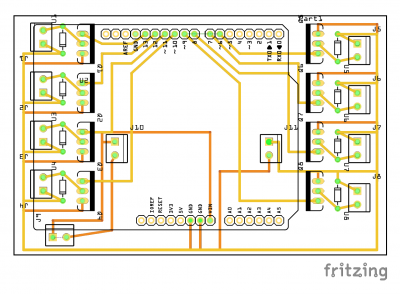
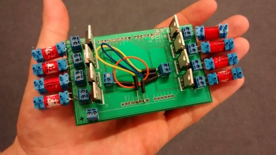
Printed Circuit Board
A prototype for the electrical system was built on a breadboard for the five-legged designs, using NPN transistors to control the valves and diodes to handle current discharge from the valves. When scaling the design to an eight valve system, the circuit became far more fragile and began to fail more often. A printed circuit board (PCB) was designed to mitigate this problem. It attached to the Arduino as a shield, and the eight valves connected to screw terminals along the sides of the board. The Arduino and circuit were powered via the Arduino serial interface, as this was already being used to communicate with the youBot.
Assembly of the Hybrid Robot
Pneumatic System
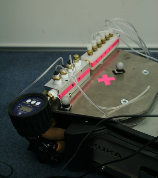
For the initial testing of the soft robots, a compressed air tank system was used along with a pressure regulator to limit the internal pressure of an existing manifold. A series of three-way solenoid valves connected to the ports of the manifold would open and pressurize the channels, or close and restore the channels to atmospheric pressure.
The main problem encountered with this system was leakage at the channel interface. Inserting the tubes into the channels without adhesive was sufficient for early testing of the starfish and quadruped robots. Over time, this caused the interfaces to grow wider, letting air out of the robot and decreasing the maximum attainable curvature of the corresponding leg, and uniformity of pressurization. To solve this problem, we attempted to bind the tubes to the legs using first silicone, then ethyl cyanoacrylate (Krazy Glue). Only the cyanoacrylate closed the interfaces successfully. A pressure sensor (with digital readout) was added to assist with open-loop testing of the soft robots.
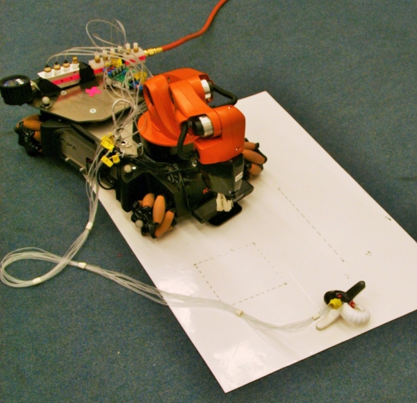
For final testing of the system and demonstration, the manifold and valves were mounted onto the youBot base plate, as pictured below.
Testing
Demonstration Day at Cornell University
In our last days of working together as a group in person, we demonstrated our results with other research teams in the department. The videos below show our demonstration, annotated slightly for clarity. The situation is meant to simulate the youBot finding a red object then closing in on it to determine if it can or cannot pick up the object on its own. For the sake of the demonstration, the youBot was hardcoded to believe that it could not reach the object on its own due to an obstacle, and the obstacle (such as a small table or ledge) was not including in the demonstration for ease of filming and seeing exactly what was going on with the minion bot.
|
(If your computer can handle it, the above video is best viewed in 1080p for full effect) |
As you can see at the end of the video, the youBot believes that the minion bot is on top of the red object prematurely and commands it to go into its grab function. This is most likely the product of inaccuracies in the distance sensor of the camera on the youBot, and could most likely be mitigated in future iterations if they were to occur.
To demonstrate that the minion bot can in fact grab hold of the intended object, we then placed the minion bot on the object and instructed it to go into its grab function. The below video shows the result.
The remaining task would be to get the minion bot back to the youBot to be picked up again. It is possible that the remaining two legs of the minion bot would be enough to shuffle the bot back out from the confined area, at least far enough to be in the reach of the youBot. If this were not to be the case, then it is possible that the youBot could draw in the minion bot directly using something like a winch which would pull on the tether. Then once the minion bot is close enough to the youBot it can be picked up again. These are efforts we would pursue in future iterations that do seem generally feasible.
Controlling the KUKA youBot
Path Planning with the youBot Manipulator
We developed a control program in ROS for automating the KUKA youBot arm. This program takes advantage of the Moveit! ROS package that uses forward and inverse kinematics plan a feasible path for the arm that does not exceed its mechanical limits. Using forward kinematics, a set of poses were saved and stored under names for quick and easy manipulation of the arm. From these positions, individual joints could be singularly adjusted, allowing for refinements in positions without wasting significant time planning to unknown locations. The positions required fine tuning as testing was conducted.
The youBot's manipulator was extensively tested to ensure that the arm could achieve the proper position without hitting certain limits or becoming a potential danger to objects or people within the vicinity of the arm. One such limit was an overcurrent limit, which was meant to prevent damage to the motors controlling the linkages. This limit would often be raised when the arm moved significant angles with the base rotation joint. Part of this testing involved rapid iteration of setting goal positions, planning to those positions, and moving to those positions. This was completed by writing and running python test scripts that would take user input and automatically set the goal state, plan to it, and move the arm to it. This testing was done outside of the state machine meant to combine the youBot arm, the youBot base, and the soft robot into a single file controlling the entirely autonomous system.
Upon testing, a path planned with MoveIt! between the pickup and to drop-off positions resulting in a path that interfered with the youBot. An effective solution was to plan a path with three points instead of two- an intermediate pose was placed between pickup and drop-off which forced the arm to raise the soft robot then plan between positions from a higher point in space where the soft robot would not be entangled in the wires.

Furthermore, to avoid obstructing the camera view and detection of the object to be retrieved, the soft robot had to be dropped off the right side of the robot. Additionally, when retrieving the robot, the youBot was maneuvered to be just off the left side of the robot. This prevented the robotic arm from circling almost three hundred and sixty degrees to reach the robot if it was off the left side of the youBot. From the camera view, the robotic arms base rotation joint was moved in order to pickup the robot. Since the arm was left in the position that dropped the soft robot on the ground, this was the simplest way to retrieve the robot and object.
Finally, the arm would need to return the soft robot, but the soft robot was now inflated and holding another object. Because of this, a point higher off the back and centralized to the back plate was chosen. This provided enough room for the soft robot to stay without rolling off the youBot from its momentum of being dropped. Throughout all of this, the robot had to have repeatability to consistently be able to retrieve the robot.
Soft-Robot - youBot Manipulation Testing
Once the arm could operate smoothly without interaction with other objects, the arm was tested in moving the soft robot within the state machine created to control both the base and arm of the youBot. This started with running the required positions without the soft robot, as shown by the attached videos.
Obvious from the videos is the error in the controller, creating significant deviation from set positions and jarring, sporadic motions. Further refinement was required before the final integration with the soft robot to produce smooth motions. To solve this issue, the controller parameters were adjusted and the velocity of the arm reduced. An added bonus of the reduced arm velocity was the reduced tension on the tubes of the soft robot when integrated. In the final video found on the integration page, you will see that the arm moves incredibly smoothly and accurately due to the reduced velocity.
Controlling the Soft Robot
Testing Soft Robot Gaits
Unless otherwise indicated, all testing described in this section was conducted on a smooth plastic substrate surface on level ground. The rationale for this choice was to provide a surface that allowed for repeated experiments and may be easily marked to more readily evaluate gait performance.
For the five-legged soft robots, an undulating gait was used to test to move the robot forward. This gait was achieved by inflating the back three legs, then the front two, then deflating the back three legs, then the front two. The legs would inflate sharply and move the contact points with the ground forward, and deflate slowly so the contact points with the ground would not move back to their initial positions. We also developed a turning gait in which one leg was used as a pivot and the other four legs inflated and deflated in sequence. Using these two gaits, the soft robot can move to any point in a plane, with any orientation. By observing how much each gait cause the soft robot to drift while translating or rotating, an open-loop control motion sequence was created to keep the soft robot moving in a near-perfect straight line by correcting for drift, maintaining a heading along the line as well. However, with the turning gait, any change in angle occurred very slowly.
Since the four-legged designs were symmetric, a turning gait was not needed to allow the robot to move to any point in a plane. Instead, by composing the backward/forward motions with side-to-side motions, the soft robot could move to any point in a plane much faster than it would if it needed to rotate. To develop a translating gait, we used a paddling motion motivated by a soft robot gait previously used by Stokes, et. al., 2014.
In this scheme, the four-legged design independently actuated two channels per leg. The back channel would inflate first, increasing the curvature of the leg and pushing the leg forward. Then the front channel would inflate, increasing the curvature of the leg again while pushing the leg back. The back channel would then deflate, pushing the leg even further back and decreasing the curvature of the leg. And finally, the front channel would deflate, decreasing the curvature of the leg and ending the cycle. This sequence could be performed synchronously by diametrically opposed legs to move the soft robot perpendicular to the axis between both legs provided that the deflate times were longer than the inflate times (by the same reason as the undulating gait for the five-legged soft robots). By interleaving the inflation and deflation of opposite pairs of diametrically opposed legs, the soft robot could move quickly in a theoretically straight line while remaining raised up off the ground. To compensate for drift, a simple control system was implemented.
The Arduino code used for the quadruped robot in this project is provided below.
Testing the Grasping Function
The grasping command used for the five-legged soft robot was primarily motivated by the design with one channel servicing all five legs (a design used for gripping). By actuating all five legs at once, the soft robot could grasp items placed below it. Since the five-legged soft robot could not achieve a paddling motion and instead used an undulating gait, it could not raise itself over any objects without external help. This, along with speed, was a main motivator for moving to a four-legged design.
With the quadruped design, we initially attempted to inflate each of the eight channels to grasp objects once the robot had raised itself over them. However, the pressure in the manifold needed to translate the soft robot was too high for the grasping sequence, and while testing the sequence, a channel burst on one of the test robots.
We then attempted to pulse the valves in order to maintain a lower average pressure in each of the channels. With this method, the valves needed to open and close at a high frequency for the legs to hold onto an object (otherwise the pressure in the legs would vary too much around a mean value, and the object being grasped would be dropped). However, with all eight solenoid valves opening and closing at the necessary frequency, dangerous amounts of current were drawn from the Arduino.
To mitigate this problem, the same method was attempted but for only one channel per leg. This solved the problems with current drawn, but introduced new problems with excess strain on the legs now that each leg would twist as well as inflate. We resolved this issue by only actuating four channels on two diametrically opposed legs. This method grasped objects successfully and was used in our final demonstration.
| gaits.pdf | 84 KB |