Design
This project consists of the development of a soft manipulator based on antagonistic actuation capable of bending and extension with a certain degree of stiffness control. It makes use of a hybrid actuation system composed of pneumatic and tendon-based actuators.
This section presents the design of each part that compose the robot, while providing the operation principles that led to that particular design.
Designing the pneumatic actuators
The first step in this project was to design the pneumatic actuators. The idea was to design actuators that extend when compressed air is injected inside them, contrary to the operation of the McKibben actuators that contract when pressurized. Actuators made of silicone that do not require a braided sleeve in order to constrain the deformation were desired. This choice led to a design of our actuators with a “folded” shape, similar to an accordion.
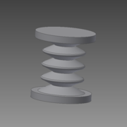 |
When pressure is applied inside the cavity of the actuator, the walls of the actuator unfold and produce an elongation of the actuator.

Since the time required to build the actuators is considerable, we first simulated it to confirm the expected behavior. This simulation is based on the Finite Element model of the actuator and was performed using the SOFA Framework (https://www.sofa-framework.org). Once the simulation provides satisfying results, we proceed with the fabrication of the actuators.
|
|
Having the simulation of the deformable parts of the prototype is of great help because it gives a good idea how these parts will behave before their fabrication. By analyzing the simulation, we know if the design needs modifications without having to test the real part in the lab. Also, a suitable way to pilot this model is by using using this model in open loop with the real prototype.
Design of a Stewart platform like section
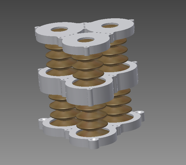
To achieve bending in our robot, three actuators are arranged in parallel configuration as one section of the manipulator. A rigid platform at the end of the array holds the actuators in place. By applying different pressure values to each actuator, we can displace or orientate this platform.
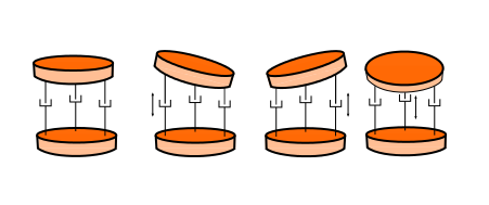
When differential pressures are applied to the actuators of one section, the top platform is oriented in different ways. If equal pressure is applied to all the actuators, the manipulator elongates longitudinally.
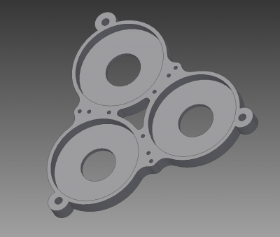
The design of the platform is very simple. It is composed of 3 sockets that receive the actuators and hold them in place. A hole at the bottom of each socket provides the necessary space to connect a plastic tube, from the air supply to the actuator, and a central hole in the platform allows us to pass the tube that will supply the air to the actuators of the second section. Smaller holes located between the sockets serve as cable guides for the tendons.
The manipulator is composed by serially connecting two sections. The pose of the manipulator is controlled by six pneumatic inputs, while the stiffness is controlled by six antagonist cable actuators. These cables run along the same direction of the pneumatic actuators and pass through holes in the rigid platform. The cables are positioned carefully to avoid contact with the pneumatic actuators and minimize the friction during bending.
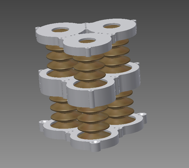
Once the behavior of one section of the manipulator was proven, another simulation was made to include both sections to better picture the behavior of the whole manipulator.
Additional Parts
|
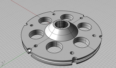
Each tendon is attached to a servomotor. More specifically, to a pulley that is connected to the shaft of each servomotor. This is why six supports of servomotors and six pulleys were designed and built. The servomotors used are rated to a 0° to 180° span, although in practice, each one turns in the range of 35° and 158°. That means we need to use a pulley that could give us enough force to pull the different parts of the manipulator, while keeping an appropriate stroke according to the simulation's results. Each section of the manipulator was measured to an elongation of 1.5cm, twice this distance must be considered for the second section. Therefore, a pulley of 3.6cm of diameter was designed , giving a safe 3.8 cm of stroke.
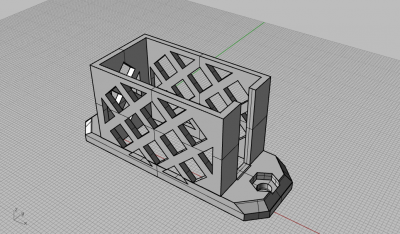
To keep the servomotors in place, a support visible on the picture below had to be designed. This design allows the six actuators to work in a reduced volume, while keeping the cables free from tangling up and leaving at the same time enough room for the pneumatics tubing.
|
