Tunable segmented soft actuators
Many of the existing pneumatic soft actuators have a fixed response after fabrication. This means that once they are fabricated, the actuators always bend, twist or stretch in the same way upon inflation. In most cases, this is desirable because this way actuators can be designed specifically for a particular application. However, what if the application or environment in which the actuator is going to work is not yet known? In this case an actuator for which the response can be easily tuned would be very useful.
In this project we fabricate extending actuator segments with a slightly different response (pressure-volume relation), that when combined, can result in segmented actuators with highly different (nonlinear) responses. The purpose of the project that is described here is to give a detailed description of the design, fabrication and testing of these soft actuators, and to provide a quick way to get you started with off-the-shelve components. For a deeper discussion on the theory and fundamental principles underlying these segmented actuators, we refer you to a previously published research article (J.T.B. Overvelde, T. Kloek, J.J.A. D’haen, K. Bertoldi, (2015) Amplifying the Response of Soft Actuators by Harnessing Snap-through Instabilities. Proceedings of the National Academic of Sciences of the United States of America).
The following movie uncovers the inspiration of the project, and shows some examples of segmented actuators that can be made using our approach.
Design and fabrication of segments
Typically, when fabricating soft actuators the aim is to design them such that their relation between input and output is as close to linear as possible. Therefore, pneumatic actuators are designed such that they have a linear relation between pressure and volume. While this simplifies the control of these actuators, it also limits the range of responses that can be achieved. In this project we take the opposite approach, and design soft pneumatic actuators with a highly nonlinear response. This allows for a larger range of responses, and as such the actuators can be embedded with a mechanical “intelligence”.
To achieve tunable actuators, we assemble them from a number of inflatable segments. To create the preferred nonlinear response, each individual segment needs to:
(requirement 1) show an initial peak in its pressure-volume relation
(requirement 2) show a softening thereafter
(requirement 3) show a final steep increase in pressure
In addition, we would also like to be able to tune the response of the segments by making simple changes to their design (requirement 4).
Using tubes as segments
One particular system that shows this behavior is a simple rubber balloon. Inflating a rubber balloon initially requires a relatively high pressure. After this initial peak, it becomes easier to inflate a balloon. However, at some point the rubber is stretched so much that it will start to stiffen (before the balloon wil explode). We aim to make actuator segments with a similar response, and that can be easily tuned by changing some dimensions.
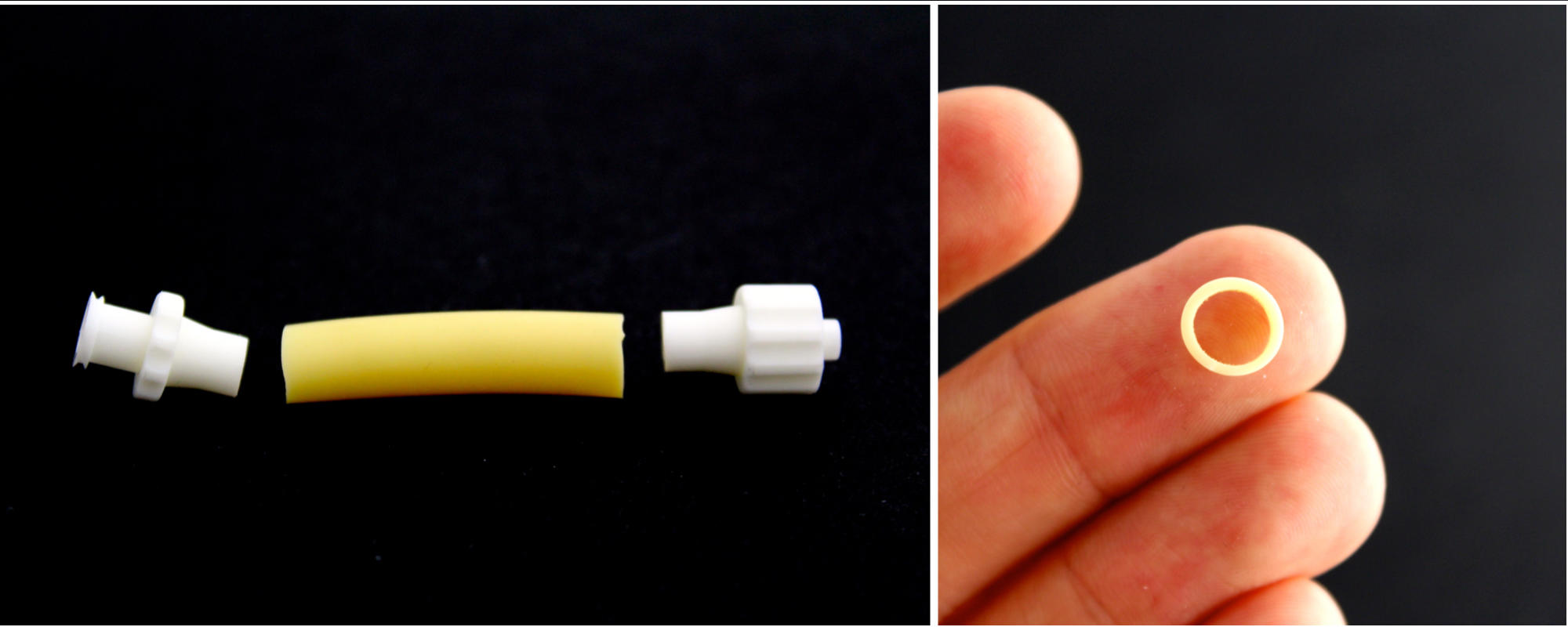
Taking inspiration from balloons, we start by fabricating individual inflatable segments from rubber tubes. To make segments that can be easily assembled into segmented actuators, we glue the tube at each end to luer-lock couplings (one plug and one socket connection).
Upon inflation of these segments, we find that the initial peak in pressure (requirement 1) and softening thereafter (requirement 2) are met, but we do not observe any stiffening within reasonable limits of applied volume. Moreover, the response of the segments doesn’t depend on the length of the tubes, which makes it more difficult to tune their nonlinear response (this is due to the fact that the tube locally bulges upon inflation). Note that we inflated the tubes with water, so that we know exactly how much volume we add to the system (water is incompressible). Air can be used as well, but the pressure-volume response of the segment will look different.
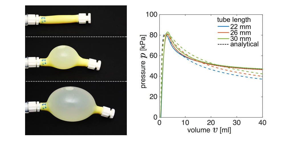
While it is also possible to tune the response of the segment by changing its radius and thickness and by using a material with a different stiffness, all these properties depend on the availability of materials, and can therefore not be changed continuously (in contrast to the length).
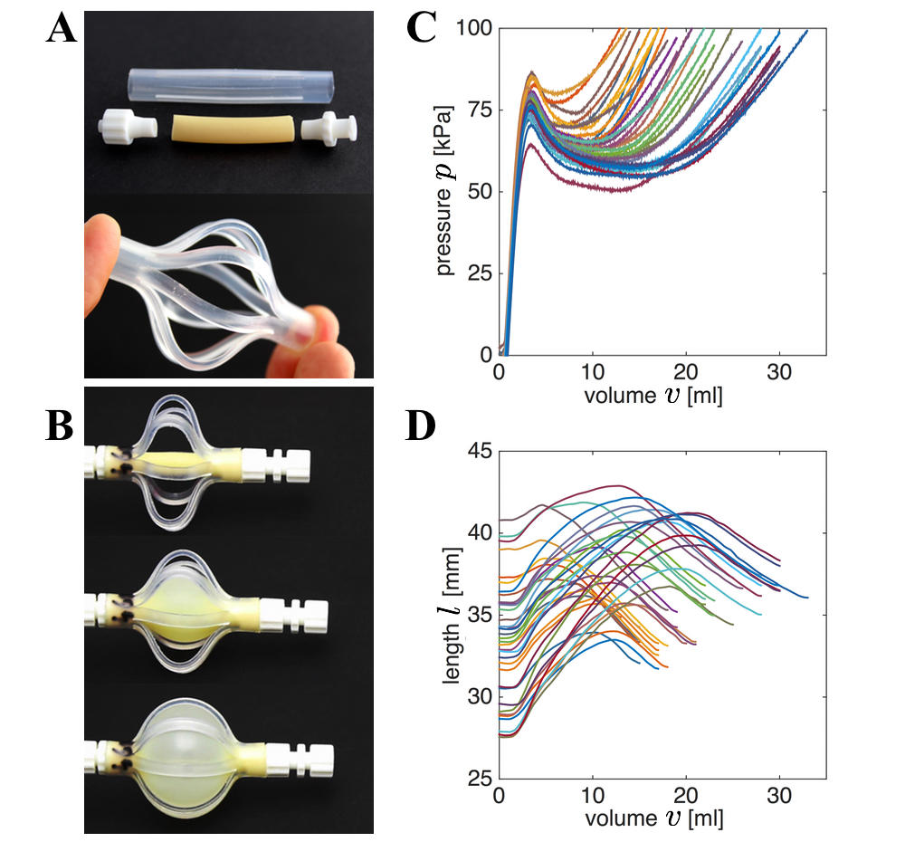
Adding braids to the segments
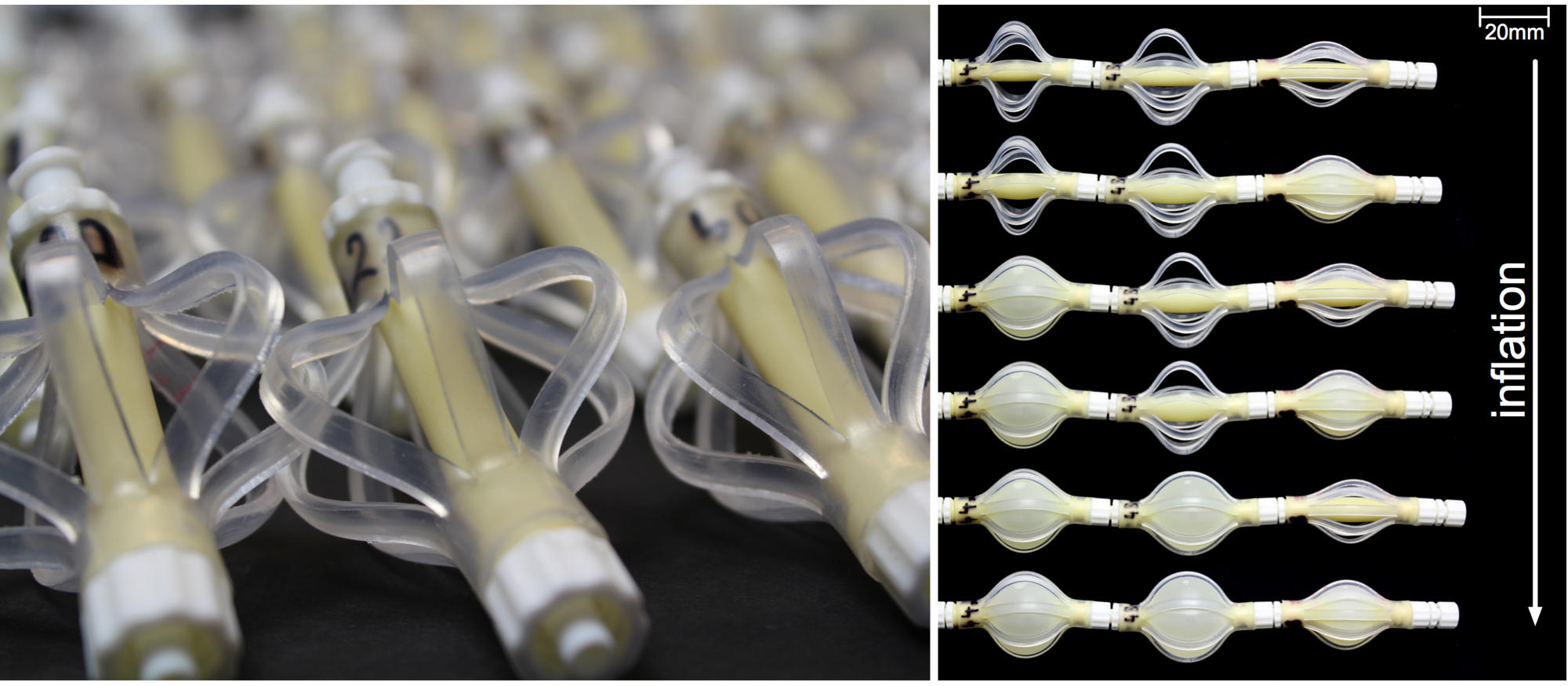
To make inflatable segments for which the response can be more easily tuned (requirement 4), and that also show a stiffening response for higher volumes (requirement 3), we add an additional component to the tubes which we refer to as braids. To fabricate these braids, we start from a stiffer tube (much stiffer than the rubber tube, but still a bit flexible), and cut slits along the length of this tube using a 3D printed tool. This process forms braids along the length of the tube, which upon compression buckle outward. When enclosing the rubber tube with these braids, at some volume the braids and tube come into contact, resulting in an increase in pressure (requirement 3). Note that changing the length of the braids and changing the length of the tube now both have an effect on the pressure-volume relation, and can therefore both be used to tune the response of the inflatable segments.
The next video shows the inflation of an individual segment.
Steps to fabricate braided segments
Previous part introduced and tested inflatable segments that satisfy all four requirement. In this part, we describe the steps required to fabricate the braided segments. More information on the materials used and where to order are given in the detailed information section.
(step 1): Cut the rubber tube to the preferred length (make sure you add additional length for the regions that will be glued the luer-lock fittings).
(step 2): Glue on one side a luer-lock with a plug coupling from which the barb has been cut using a sharp knife.
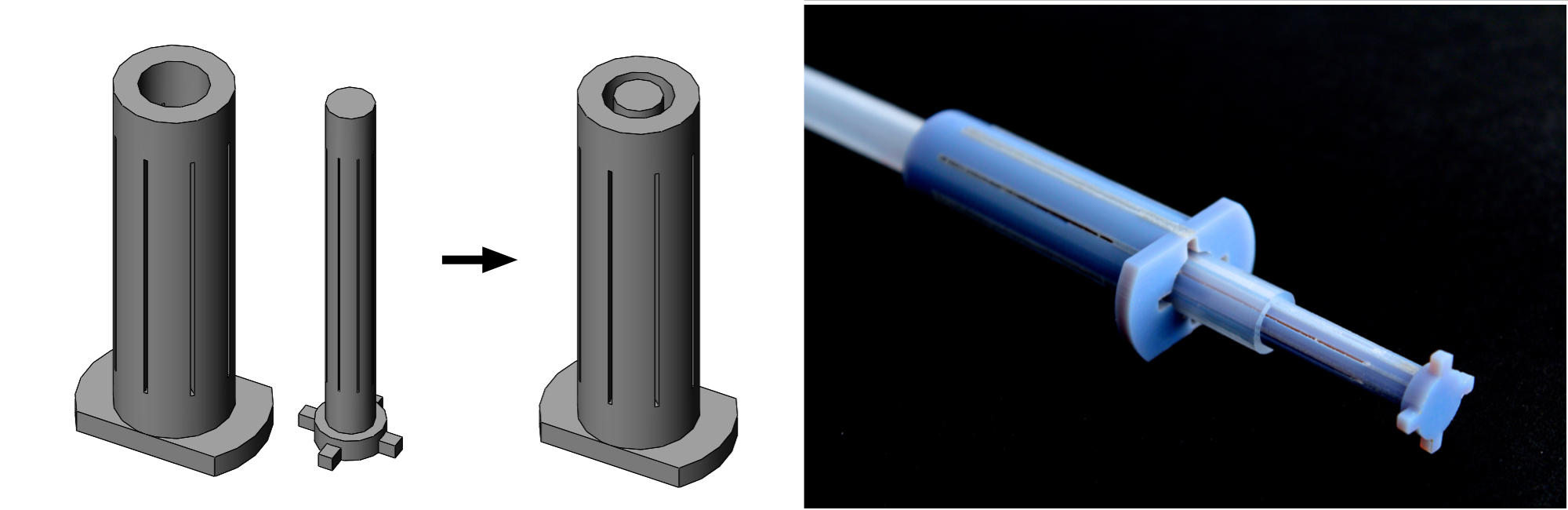
(step 3): Using the 3D printed tool (files can be found in the detailed information section), cut the polyethylene tube to fabricate the braids.
(step 4): Slide the braided tube over the rubber tube, and glue the braided tube to the rubber tube by applying glue to the rubber tube.
(step 5): Make sure the free end of the rubber tube goes through the free end of the braided tube, and glue to tube to a luer-lock with a socket coupling from which the barb has been cut. You need to buckle the braids during this process, to make enough room to glue the rubber tube to the luer-lock coupling.
(Step 6): Now finish the segment by applying glue to the end of the rubber tube, and fixing the free end of the braided tube.
Note that for the actuator to work, the rubber tube needs to be shorter than the length of the braids. The actuators we fabricated consisted of rubber tubes ranging between 20-30mm, and braids between 40-50mm.
Design alterations and improvements
While these segment show the preferred pressure-volume relation, they are not the most efficient actuators when it comes to the changes in length. The maximum values we obtained were around a 40% increase, but this depends on the length of the rubber tube and braids used to fabricate the segments. Although we don’t discuss possible alterations in details, we want to note a few possibilities to change the response besides changing the length of the tubes and braids:
(alteration 1): To make a bending actuator, you can leave a few slits on one side of the braided tube uncut. This only results in buckling of the braids at one side of the segments, causing it to bend.
(alteration 2): The slits can be cut at an angle to create a twisting segment.
(alteration 3): The braids could possibly be replaced by different structures to guide the deformation more efficiently (think for example of origami tubes).
Assembling segmented actuators
In previous part we described the design and fabrication of inflatable segments with a nonlinear relation between pressure and volume. In this section we outline the process of assembling the segments, resulting in new actuators with a different responses. By simply combining different segments, the response of the final actuator can be tuned, and we show some examples of the responses that can be achieved.
Two-balloon experiment
A simple experiment that is of interest, involves two balloons that illustrate the “strange” response that can be achieved when combining segments with a nonlinear relation between pressure and volume.
In the experiment, two balloons are partially inflated and connected by tubes and a valve. If the response of the balloons would be linear, the volume of the balloons would equalize and both would remain inflated. However, the response is nonlinear, and we can use this nonlinearity to create unexpected responses such as the one shown in the movie, in which one balloon completely empties into the other.
Combining segments
Using the previously made segments, we can play the same game as with the balloons, and start to program the response of the segmented actuators in different ways. While a complete numerical procedure to find actuators with specific responses is outlined in the related publication, here we focus on some specific actuators that we assembled and that show an interesting response.
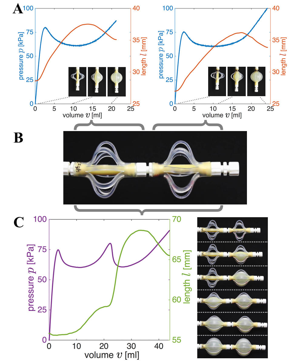
The first segmented actuator we tested consists of two segments, one segment has a tube length of 30mm and a braid length of 48mm, while the other segment has a tube length of 20mm and a braid length of 50mm. The inflation of this actuator is shown in the following movie.
There are two very interesting features about this actuator that make it different from the usual (nearly linear) soft actuators. First, upon inflation of the actuator only one of the segments inflates, similar to what we see in the two-balloon experiment. Second, about halfway through the inflation, an instability occurs and the second segment also starts to inflate. This sudden transition also triggers a sudden increase in length.
The second segmented actuator we tested also consists of two segments, one segment has a tube length of 30mm and a braid length of 44mm, while the other segment has a tube length of 26mm and a braid length of 48mm. The response of this actuator is shown below.
While the tube and braid lengths have only been slightly changed, the response is very different. Initially, again only one of the segments inflates, however, at some point along the inflation the actuator suddenly completely changes shape and all volume flows from one segment to the other. This clearly indicates that inflation sequences can be programmed into the actuator, which can be easily tuned through assembly of different segments.
To illustrate the fact that many of the transitions occur instantaneously, we also assembled an actuator using three segments with (tube length, braid length) equal to (28mm, 40mm), (30mm, 44mm), and (24mm, 50mm). Now, we inflate the actuator to a point just before a transition point, and decouple the system from the syringe pump. We connect a small pocket to the system, and slightly increase the volume in the actuator by squeezing the pocket at shown in the following movie.
This small increase in volume triggers an instability in the system, causing all the volume from the two outer segments to flow into the center segment. Really interesting behavior!
Increasing the actuation speed
In this study we used water to actuate the segments (due to its incompressibility). However, it is important to note that the actuation speed of the proposed actuators can be greatly increased by supplying air. In fact, we find that water introduces significant inertia during inflation, limiting the actuation speed. It typically takes more than 1 second for the changes in length, pressure, and internal volume induced by the sudden transition to fully take place. However, by simply using air to actuate the system and by adding a small reservoir to increase the energy stored in the system, the actuation time can be significantly reduced to 0.1 second, as shown in the following movie.
This movie highlights the potential of these segmented actuators for applications where speed is important. Although this actuation time is similar to that of existing high-speed soft actuators, only a small volume of supplied fluid is required to actuate the system because we exploit snap-through instabilities at constant volume. Therefore, relatively small compressors are sufficient to inflate these actuators, making them highly suitable for untethered applications and robots.
Detailed information
Materials
Materials to fabricate the segments were ordered at McMASTER-CARR. To fabricate the inflatable segments we used:
| (rubber tube) | Super-soft latex rubber semi-clear tubing with a 1/4” inner diameter and 5/16” outer diameter | [product ID: 5234K98] |
| (polyethylene tube) | High-flex polyethylene-lined semi-clear tubing with a 5/16” inner diamater and 7/16” outer diamater | [product ID: 5155K28] |
| (luer lock plug) | Lightweight quick-turn impact resistant tube couplings for 1/4” tube diameter | [product ID: 51525K36] |
| (luer lock socket) | Lightweight quick-turn impact resistant tube couplings for 1/4” tube diameter | [product ID: 51525K29] |
| (glue) | Brush-on instant-bonding adhesive, general purpose to fill gaps up to 0.01” | [product ID: 7729A24] |
To connect the actuators to the pressure source, and to close the segments, we furthermore furthermore used:
| (luer lock plug cap) | Lightweight quick-turn impact resistant tube couplings | [product ID: 51525K38] |
| (luer lock socket cap) | Lightweight quick-turn impact resistant tube couplings | [product ID: 51525K37] |
| (PVC tubing) | Masterkleer PVC clear tubing with a 5/16” inner diameter and 1/2” outer diameter | [product ID: 5233K62] |
Tools that we used:
| (razor blade) | Stainless steel razor blade | [product ID: 3962A1] |
Note that these product ID codes were last updated June 2016.
Tool to fabricate braids
To fabricate the braided tubes, we made a tool using a 3D printer that guides a knife for cutting the slits. The tool consists of two parts, part 1 is placed inside the polyethylene tube, while part 2 is placed external and helps guide the cutting.
3D printing was done on a Stratasys Objet30, based on six sets of stl files for braid lengths ranging between 40-50mm. The files can be downloaded through this link.
If you want to change the model, make different lengths, or use different radii for the tubes, you can also start from the Solid Works Part that can be downloaded from here.
Experimental setup
To measure the pressure-volume response of the segments and segmented actuators, we build an experimental setup containing the following components:
| (syringe pump) | Standard infuse/Withdraw PHD Ultra, Harvard Apparatus |
| (50-mL syringes) | 1000 series, Hamilton Company |
| (pressure sensor) | MPX5100; Freescale Semiconductor 0-100kPa |
| (data acquisition system) | NI USB-6009, National Instruments |