Artificial eyelid closure using soft exopatches
The major symptom of Bell’s Palsy (and other facial nerve related illnesses) is an inability to close the eyelid or blink, which can lead to blindness if left untreated. Although most patients recover fully in 3 months, most treatment methods require invasive, surgery. Our project aims to build a device using an "exopatch" which can contract and provide downwards force on the eyelid to artificially recreate a blink motion.
An easy to use, exosuit type device that can close the eye effectively and be easily taken on & off could provide a way of treating the condition without having to undergo invasive surgery, offering a treatment method for a debilitating condition that affects over a million people worldwide each year.

Our team is "Nictus", consisting of a few engineering and medical students studying at UNSW in Sydney, Australia. Thanks is provided to Dr. John Daniels, from the School of Materials Science and Engineering at UNSW for supervision. Support from the NSW Office for Science and Research for this work as part of the Science and Engineering Student Competition Sponsorship Program is also gratefully acknowledged.
![]()
Background
Bell’s palsy, involving paralysis of any structures innervated by the facial nerve, is a debilitating condition affecting over 1 million people new patients per year worldwide, with over 40'000 per year in the US. The key function of the facial nerve is eyelid closure, which protects and lubricates the eye. A lack of effective lubrication can cause pain and inflammation. Patients describe chronic nerve paralysis, and the resulting inability to close the eyelid and lubricate the eyes, as like "having sandpaper in the eye". In extreme cases, this can result in blindness.

(Illustration from WebMD)
A number of surgical methods have been used to ‘reanimate’ eyelids in facial paralysis (e.g. gold weight implantation, which can . However, they are unable to achieve spontaneous (quick) and synchronous eye closure and do not provide effective lubrication, which is essential for preserving healthy eyesight [1].
This project grew from a project at UNSW/The Sydney Facial Nerve Clinic to develop an implantable artificial blinking device. However, we realised quickly that all current clinical methods of reanimation require invasive surgery [2]. This is undesirable given Bell’s Palsy is a temporary condition – 70% of patients recover without intervention within 3-5 months, during which period surgical intervention is not considered [3]. Commonly used non-surgical methods of closure involve taping the eyelid shut or frequently applying eye-drops. These are obviously not ideal - they are either ineffective or detract significantly from the patient’s quality of life. A more effective and ergonomic solution to manage Bell’s palsy over the short-term is required. This project aims to develop a non-surgical method of eyelid closure using a system of actuators, connected to the lid via soft, compliant patches, to apply some closure force and displacement to the impaired eyelid.
A schematic of the proposed mechanism is shown in Figure 1, below and connector from actuator to lid (white) shown.")
The device would work by sensing the blink impulse from the healthy hemisphere via surface EMG, and activating an actuator which would transfer force and displacement to the impaired eyelid, dragging or pushing it closed.
Sensing of the blink impulse from the healthy hemisphere of the face has been successfully demonstrated and will not be tested here [4]. However, an appropriate, external, mechanical closure motion has not been developed. Existing or proposed methods of external closure either involve surface based electrical stimulation nerve or (carried out primarily by Frigerio et al. and reported to be uncomfortable even with acute usage as per the Wong-Baker FACES scale) or sticking electromagnets to the eyelid (the weight and comfort of which were not discussed). The current project will focus on developing prototype devices to test mechanisms of closure that replicate the natural, sphincter like mechanical closure motion of the eyelid while minimising on-eyelid weight using soft, compliant patches. This will be approached either using soft slings or pneumatic patches.
This project has the potential to lead to a device which could provide comfort and improve the daily lives of those suffering from a physically and emotionally debilitating condition.
References:
[1] N. Jayashankar, K. P. Morwani, M. J. Shaan, S. R. Bhatia, and K. T. Patil, "Customized gold weight eyelid implantation in paralytic lagophthalmos," J Laryngol Otol, vol. 122, pp. 1088-91, Oct 2008.
[2] T. T. Tollefson and C. W. Senders, "Restoration of eyelid closure in facial paralysis using artificial muscle: preliminary cadaveric analysis," Laryngoscope, vol. 117, pp. 1907-11, Nov 2007.
[3] S. Hasmat, "Exploring the feasibility of creating eye closure using electromagnets and magnets in patients with facial nerve paralysis," Independent Learning Project, Faculty of Medicine & Graduate School of Biomedical Engineering, University of New South Wales, Sydney, 2014.
[4] M. Kurita, A. Takushima, Y. Muraoka, T. Shiraishi, and K. Harii, "Feasibility of bionic reanimation of a paralyzed face: a preliminary study of functional electrical stimulation of a paralyzed facial muscle controlled with the electromyography of the contralateral healthy hemiface," Plast Reconstr Surg, vol. 126, pp. 81e-3e, Aug 2010.
Design Overview/Requirements
The concept behind the designs are to emulate the natural eyeblink to maximal degree possible. Specific designs are discussed in their subpages, overall requirements and a description of anatomy is provided here.
Natural Eyeblink

Eyelid closure occurs naturally via the activation of the sphincter like orbicularis oculi (OOc) muscle (pictured above, image from Grey's Anatomy). The eyelid is kept tonically open via the levator palpebrae superioris muscle (LPS) which becomes inactive during the blink impulse. The eyelid is brought downwards slightly due to passive muscle tension prior to activation of the OOc. The contraction of the sphincter like OOc muscle around the eyelid pushes folds of skin in the eyelid downwards and closed in a complex motion.
It should be clarified - the design is not required to account for eyelid opening. The LPS is generally unaffected and can open the eyelid open, only closure needs to be addressed.
Other key requirements are outlined.
Effectiveness of Closure
The device should achieve full closure. The force and displacement requirements are difficult to estimate as the vary for different closure mechanisms. However, for the linear sling design used by Tollefson and Senders to create an implantable closure device (effective on cadavers), force requirements were 654mN and 8mm closure (see reference [2] in Background). The actuator should ideally (although not necessarily) exceed these minimum requirements.
Closure should ideally occur within 80-100ms (natural closure times), however slower times are acceptable.
Ease of Use & Comfort
The device should be easy to apply and remove.
Closure should not be uncomfortable.
Safety
The device should not apply excessive force or displacement such that tissue is injured. It shouldn't cause irritation over long term usage (although this is hard to measure in this study.
1. Force transfer by constrained string - (Main Design)
Overall Design Summary:
A string based design which creates a sphincter like closure motion is described in the below Figure. A patch with holes, or struts for connector string to pass through is attached to the rim of the eyelid. On either side of the eyelid, the string is constrained. When the string is pulled from its lateral attachment and forced to tighten the eyelid is also forced downwards, as the tightening creates a downwards motion on the struts and hence the eyelid. This method could be extended to the lower eyelid to create a full sphincter like motion.

To skip a few steps, how it looks in the end (without the actuator) is shown in the figure, below. 
It is important to note - here the string being pulled sideways creates a downwards force on the struts and hence the lid (as opposed to a side/lateral force). The string is fixed at the nasal point in a ball of epoxy and is allowed to slide through the attachment on the lateral side of the eye (such that it is constrained to pass through a comfortable direction before reaching the actuator situated on glasses.)
Disadvantages of and Modifications to Design
Key modifications and areas for future work are described in the "Testing" section outlining results and whether the device meet spec.
Some possible modifications, alternate designs, or work leading to this design are discussed in the alternate design subsections.
However, it is immediately apparent that alterations to geometry (e.g. thicknesses of moulds and size of struts, or positioning of elements on the face) could be optimised to a greater degree than they have been here.
Materials
Patch Related Materials
Ecoflex Silicone elastomer was used to fabricate the patches. This was due to the material being FDA approved for skin contact, while being (sufficiently) strong while still highly compliant. The patches are required to be highly flexible to conform to skin surfaces while bearing some load. 00 and 05 grade silicones were tested - 05 was used as 00 tore a few times during the fabrication process, as the parts were very thin to maximise comfort. The greater the mass/volume on the lid, the greater the noticeability of the device.
During manufacture, 3D printed (some with resin, some using ABS) struts with holes/channels inside were embedded into the structure during curing. This was to provide a smooth, strong and low friction surface (in contrast with silicone) through which the fibre could pass through. Low friction is important - having a sticky surface would mean some of the lateral movement of the fibre would be transferred to the patch. Using normal pneumatic tubing was considered, but there was a tendency for it to stick to fibre and not slide through smoothly.
Kevlar thread was used as the "string" to transfer force. This was mostly due to it being smooth and not liable to fraying, making it easy to thread into tubing and struts. Household string could have been used instead.
Clear Band-Aid was used to attach components to skin due to its biocompatibility and easy of use. Other medical grade adhesives were considered, but were more difficult to work with in the fabrication process.
Glasses/Actuation Materials
A standard pair of laboratory safety glasses were used as the testing glasses to which the actuator was attached.
A linear actuator capable of 20mm of actuation (in 800ms) from Firgelli Motors (PQ-12) was used as the actuator. While this is slower than that the closure time of the eyelid (80ms), this is sufficient for proof of concept testing. A commercial control board supplied was Firgelli was used for control.
Connector materials
To wear the device, first the patch/es are applied, then the actuating glasses are worn and the two are connected. Both are separate. To facilitate their connection, pneumatic tubing (connected to the patch end of the fibre) and a luer lock (connected to the actuator fibre) were used as connections. When both components are ready, the luer lock and the tubing are connected, interfacing the two components and allowing for force and displacement transfer.
Geometry
Relevant Component Geometry
STL files for the patch moulds (for fabrication with silicone elastomer) and the 3D printed struts are provided here (as this wiki does not support the upload of STL files) :
https://drive.google.com/open?id=0B3gYzJ0u42Q4TjNMWlJ0Q3NOczA
The ideal patch dimensions for the current user (the author) wasn't known. Some guesses were made using anthropometry to construct a number of patch moulds with various widths and heights and the most comfortable/ergonomic patch for the author was chosen. The key factors were that it should be smaller than the lower fold of the upper eyelid - if it covered the entire lid the eyelid wouldn't be able to "fold out" to close. A patch with a height of 12mm and width 24mm was chosen. The depth was assessed by fabricating a number of patches and determining what was the minimum depth at which struts could easily be incorporated during moulding.
A mould image and "strut" image are provided below:


Overall Positioning of Patch on Lid
Nasal Patch: This consists of a patch of silicone, connected to the skin by bandaids with an epoxy patch from which the kevlar fibres emanate. It is positioned on the rigid contralateral side of the nose. This a fixed end point for the fibre which provides the reaction force and hence tension that creates a downwards force upon the struts during lateral pulling of the string.
On eye patch: This is positioned on the lower half of the upper eyelid, which folds down upon closure of the lid. As stated, downwards movement of the strut will push closed the lid.
Lateral constraint: From preliminary designs assessed in "Side Project - Lateral Pulling", it was determined that a 45 degree angle of depression from the mid line of the eye (directed slightly posteriorly) provided the most "comfortable" closure for the author. As such, there is a patch with an embedded strut positioned on the side of the eye. The fibre passes through this, constraining the direction of fibre pulling relative to the lid, prior to passing to the actuator.
Manufacturing
Molds were designed in Solidworks and 3D printed. Silicone elastomer was cast in these molds and cured in an oven at 60 degrees for 15 minutes. Prior to curing, struts were pushed into the silicone such that they were embedded into the final cured structure.
The manufacturing process used shall be described in greater detail in the fabrication section.
2. Lateral Pulling (Preliminary Design)
Background and Overview:
Prior to attempting the main soft exopatch device, the concept of external eyelid closure was explored by considering the possibility of achieving closure by attaching a connector to the lid (e.g. a Band-Aid with string) and pulling laterally using an actuator.
The linear sling method, using a sling harvested from temporalis muscle fascia, has been used to create a working prototype of implantable active closure devices using electroactive polymers [2].
It involves harvesting patients muscle fascia, inserting it into the eyelid and pulling it laterally to drag the eyelid closed. A schematic (taken from Tollefson and Senders, 2007) outlining the concept is shown below.

It may be possible to use the same method to provide closure externally, by attaching a lateral pulling actuator to the external surface of the upper eyelid, possibly using string and Band-Aid for purposes of prototyping.
To achieve closure using an implant device, a linear actuator, must provide 6mm of unidirectional displacement and 654mN of force to a sling inserted into the upper eyelid [2].
The proposed method could involve the following key materials and geometry:
- Actuator: A linear actuator situated laterally to the lateral canthus of the eye, (able to achieve 6mm of displacement)
- Method of Attachment: String, attached to the inferior palpebral portion of the upper eyelid
- Closure Motion: Transfer of force and displacement from the linear actuator to the upper eyelid via the string.
The key requirements, are as follows:
- Actuation Displacement: Either 6mm lateral displacement, or a 6mm vertical displacement component. There is dispute regarding this requirement.
- Force: 20-100gmf force if activated simultaneously with blink, 56-150gmf force if activated while the levator is active
- Actuation Time: Ideally within 80-100ms
The device is illustrated as per the following general schematic, representing the actuator connected to some element on the lid. The actuator would act in the right hand direction of the image.

3. Pneumatic Exopatch - (Failed Design)
This design consists of thin patches of eye-shaped, high durometer (very soft) silicone (<1mm thickness) with an air chamber inside. The Figure below explains its concept of operation.

Figure : Design description of pneumatic exopatch
A cut-out section of the unassembled patch in illustrates the top and bottom layers and the air pocket in between.

Figure: Cut-out of unassembled patch.
Improvements may be made by introducing channels in the design with strain limiting sections (e.g. with embedded stiff fibres) in between which can limit the expansion to occurring purely axially. A key challenge will be designing patches which can expand enough to provide closure while also being "strain free", or comfortable, while the eye is open.
Fabrication
Individual fabrication guides are listed on the subpages.
1. Force transfer by constrained string (Main) - Fabrication
This section describes the fabrication of the "on-eyelid" parts and their connection to the glasses/actuator set-up.
Materials & Equipment:
Item | Description | Key Facts/Values | Identification |
4 x AA Battery Holder | Power source holding 4 AA batteries, output of ~6V |
| http://www.createunsw.com.au/store/parts
|
Glasses | Standard Laboratory Safety Glasses | N/A | N/A. |
Eco-flex Silicone 00-30 | Low durometer, castable silicone elastomer, |
Certified as per ISO 10993-10, Biological evaluation of medical devices, Part 10: Tests for irritation and skin sensitization | https://www.smooth-on.com/tb/files/ECOFLEX_SERIES_TB.pdf
|
Firgelli LAC (Control Board) | Soldered to power supply, allows for computer based actuator position control. | N/A | https://s3-us-west-1.amazonaws.com/firgellidownloads/LAC_Datasheet.pdf
|
Kevlar Thread | For attachment of actuator to eyelid | .014" | http://www.mcmaster.com/#8800k41/=134xzba
|
BandAid Clear Waterproof Adhesives | For attachment of silicone parts to eyelid/skin | N/A | N/A |
Sil-poxy (Epoxy) | For connecting parts (e.g. actuator to glasses, or fibre starting point to silicone part no (1). | N/A | https://www.smooth-on.com/tb/files/Sil_Poxy_Silicone_Adhesive.pdf
|
Firgelli Linear Actuator (PQ-12) | For actuation to provide linear force and motion. | Outlined in more detail in following paragraph. | http://www.firgelli.com/Firgelli_PQ_12_P_Linear_Actuator_p/pq12-p.htm |
Polyurethane Tubing | For connecting glass and lid components. | 1/16" ID, 1/8" OD, | |
Luer lock | For connecting glass and lid components. |
|
|
Table 3‑1: Materials used in fabrication of linear device.
The actuator had a maximal displacement of 20mm, with built in position feedback potentiometer to allow for position control. It is capable of achieving a maximal force of 18N. The actuator was powered by a ~6V power supply. It has a speed of 28mm/s.
Fabrication Methods:
1) Test devices fabrication:
Test devices, consisting of three components of (1) the nasal attachment, (2) the "on eyelid" part and (3) the lateral directional constraint, were made by casting of silicone in 3D printed moulds.
a) An approximately 1:1 ratio by volume of the A & B mixtures of the silicone elastomer (Eco-Flex 00-30) were mixed in a plastic bowl.

b) After thorough mixing, the mixture was poured into the moulds. (The moulds were designed in Solidworks and 3D printed, STL files are available in the design section).
c) Struts were pushed into the silicone such that they would become embedded into the final cured structure.

d) The parts in the moulds were cured in an oven at 60 degrees for 15 minutes. Parts were removed from moulds after cooling using a straight razor. Some parts in moulds and removed parts are shown below.


2) Connection of individual "on-face" parts
a) After curing, Kevlar thread was inserted into the holes present in the struts, connecting the three mould pieces in the correct order, from 1-3
b) The thread was intended to originate from part number (1), and as such, was fixed in position by affixing the thread to the mould part using epoxy glue which was allowed to cure and solidify for 15 minutes.

(Note: The above image has an orange-brown liquid latex sample on the left which was used to test whether encapsulation in cured epoxy would be a suitable fixation mechanism, this wasn't used in testing.)
c) At this point, the thread orginated from its position in part (1), the nasal end (fixed by epoxy), travelled through (2), the "on-eyelid" piece and then (3), the lateral direction constraint. It was then fixed at this point to a strip of polyurethane tubing that could connect to a Luer lock from the actuator/glasses end. This done by inserting the thread into the tubing and applying epoxy and allowing to cure. The connection (as a bench set-up) is shown below.

(Note: Here peripheral items such as band-aids are shown below/around the parts. This is because at this point the aim was to use epoxy to glue adhesive to the silicone, this was abandoned later. Additionally, a bottom eyelid piece is connected here in parallel to the top eyelid piece, this was not used.)
d) The set-up was attached to the face/eyelid, using band-aid as adhesive. The following image describes the set-up.

3) Actuator component
a) A Firgelli linear actuator was wrapped in parafilm and then attached using epoxy to the left hand side of a pair of glasses. It was oriented so the actuating component was facing (and actuating) in the posterior direction. String was attached to the moving actuator component and then passed through a small protruded channel on the anterior end of the actuator that colinear with the line of action of the actuator. This ensured that no matter the angle between the direction constraint part and the actuator, actuation relative to the moving part would always occur in its line of actuation, maximising distance. This is illustrated below.

b) The actuator (Firgelli PQ-12) was connected to its control board (Firgelli LAC), which was connected to power (4xAA batteries) and a PC via USB connection. Due to the short length of the control board-actuator connection, the control board had to be held in the hand during testing.
c) The actuator thread was connected to the on eyelid section by connecting the Luer lock at the end of the actuator thread to the polyurethane tubing described earlier.

As the string is obviously far too loose in the pictured image, the thread on the eyelid end was cut and shortened until in a resting state, a small amount of displacement applied to the string was sufficient to apply tension to the eyelid. The total length of the thread (actuator and eyelid end) at this point was ~11cm.
(Note: During final live testing, the thread from the luer lock was pulled out of its connecting epoxy, so string was directly tied to the actuator component, bypassing the luer lock/tubing connection.)
2. Lateral Pulling Fabrication (Preliminary Design)
A sling device was fabricated by attaching a shape memory alloy actuator to the side of a pair of 3D glasses. The actuator was situated on the side of the glasses corresponding to the eyelid being closed. The actuator was not fixed permanently to the glasses; rather it was affixed using blu-tack to allow for adjustment of distances and lines of action, as outlined in the testing section.
Properties of materials and equipment used, as well as any methods for fabricating components or set ups are described below.
Materials & Equipment:
Item | Description | Key Facts/Values | Identification |
Benchtop power supply | Power outputs of 10V and 5V and two ground outputs. | 10V was used for this experiment. | LABEQ-335, from GSBME Teaching Laboratory |
Glasses | 3D glasses with the lenses removed | N/A | N/A. Obtained from Event Cinemas. |
Connective Electrical Equipment | Standard electrical wiring and lead free solder | Copper Wire diameter (.6mm)
| Obtained from Jaycar electronics |
Miga Motors MAD Microcontroller | Soldered to actuator and power supply, allows for push button actuator operation | N/A | MAD-3561 |
Household string | For attachment of actuator to eyelid | N/A | N/A |
BandAid Clear Waterproof Adhesives | For attachment of string to eyelid | N/A | N/A |
Blu-tack | N/A | N/A | N/A |
Miga Motors Shape Memory Alloy Actuator | For actuation to provide linear force and motion. | Outlined in more detail in following paragraph. | Miga One Linear Actuator |
Table 3‑1: Materials used in fabrication of linear device.
One actuator had a maximal displacement of 8mm and a maximal force of 8.9N. The other had a maximal displacement of 6mm and a maximum force of 7.2N. The actuator was powered by a 10V power supply, allowing it to reach peak displacement in 200ms.
Fabrication Methods:
Connections between electrically active components were made by soldering connecting wires onto appropriate areas or joining using alligator clips. Connections were made between power supply and the MAD controller & between the controller and the actuator.
Mechanical connections between components were made using blu tack or Bandaid adhesive. This was considered sufficient for the present tests. Connections were made between the actuator and string (Band-Aid), actuator and glasses (Blu-tack) and string to eyelid (Band-Aid).
A side view of the preliminary prototype is shown below:

A front view is also shown:

3. Pneumatic Exopatch Fabrication - (Failed Design)
Fabrication has been attempted. Female molds based on the part designs similar to those described above were fabricated by 3D printing (UP Box, ABS material). These were used to cast silicone parts. Silicone elastomer (Eco-Flex 0010, Smooth-On Inc., PA, US) was mixed and poured into the molds. They were then degassed in a vacuum chamber at 200mbar for 10 minutes prior to removal of excess elastomer. Parts were then cured for 15 minutes at 65C.
The samples did not have a sufficiently large air gap to allow for insertion of tubing for air transport. Additionally, the top and bottom parts of the samples adhered to each other due to the “stickiness” of the silicone material and its low rigidity. As they would inevitably collapse onto each other due to their high weight, the sticking of sides became unavoidable.
While fabrication was not pursued further within this project, the concept is believed to still be viable. Further fabrication may involve systematic variation of various geometric parameters (e.g. thickness) to determine the ideal design parameters. Additionally, higher strength elastomers may be used.
Alternate geometries are also being considered, such as simple straight channel patches with attachment points above the eyebrows and at the rims of the eyelids. These could be fabricated using thin, dry materials which can crumple under vaccum and then uncrumple, or expand under pressure, such as the plastic of common grocery plastic bags.
Testing
The validity of the final concept involved testing the effectiveness of closure as well as human-subject testing for comfort and usability. The results of this data are listed in the subsequent pages.
1. Force transfer by constrained string (main design) - Results and Testing
The ideal method of testing the device would be to trial the device on patients with impaired blinks. However, due to the lengthy ethics approval processes required, patient testing of the device is not considered in the scope of this study.
Preliminary testing, to assess the relative effectiveness of closure methods to advise future study, was conducted by trialling the device on the author. The degree of closure and measures such as “comfort” and "ease of use" were considered.
Testing without actuator
Prior to attaching the actuator, the mechanism of closure was tested. Specifically, the following question was addressed:
Can a thread pulled through a system of patches with:
- patch (1) fixing the thread origin on the nasal side;
- patch (2) transferring downwards force to the eyelid; and
- patch (3) ensuring the direction the thread was pulled was constrained
achieve eyelid closure?
This was tested by applying the patches in the described configuration and pulling the thread. The following video demonstrates the results.
This demonstrates that actuating the thread connected to the patch configuration is able to generate closure.
It was noted here that the patch on the eyelid was being slightly disconnected, this was corrected by applying more band-aid adhesive. It could be beneficial to have adhesive running across the entirety of the underside of the patch for more even attachment. It would be desirable in future to test the effect of various constraint positions on the closure.
Whether a system of patches actuated by a linear actuator is capable of achieving closure:
The actuator/glasses device outlined in the fabrication section was worn and connected to the patch thread via luer lock/tube attachment. During testing the thread was disconnected from the luer lock - the thread was reconnected directly to the actuator (as observed in the results videos). The thread was in a resting state such that applying a small amount of displacement to it would result in creating some tension on the eyelid.
The actuator was activated to provide a posterior stroke, increasing from 6mm - 16mm. Partial eyelid closure began to be observed from ~8mm stroke.
Full closure was observed from 14-16mm stroke.
Discussion
Effectiveness of Closure:
Full closure was achieved using 16mm of closure.
Lower levels of displacement were not sufficient to achieve closure. This is double the Tollefson and Senders value of 8mm for linear sling based closure. It is expected that this is due to the displacement required to take up passive eyelid tension. Some displacement needs to be applied to the eyelid to take it from a "comfortable" stress-free state to a taut state prior to movement causing eyelid closure. This should be considered in device design. It is expected that the displacement requirements will vary from person to person, and also between applications of the device (e.g. through altered constraint positions). It would be of benefit to assess these variables through a study on multiple real people, where constraint positions are systematically varied and required displacement is observed.
The closure did not meet the 80-100ms goal to replicate natural eyelid closure (it is expected approximately 600ms was the time).
Comfort & Ease of Use:
While the device was noticeable, the closure motion did not elicit discomfort.
However, the ease of use was very low. It was challenging attaching the patches in the right configuration, with adequate adhesion, and then connecting the actuator system. It took over 5 minutes to apply the device and occasionally de-adhesion would occur.
Two key areas require work:
1) An easy "on-off" interface system to allow application of the device
2) More effective materials selection and fabrication processes to allow for more reliable and easy to apply adhesion.
Validity of Self Testing:
The prototype devices were self-tested on a team member. It is possible that confirmation bias exists in reporting subjective values such as “comfort” and “noticeability” due to the involvement of the test subject (the author) with the project.
It was noticed that the right (unactuated) eyelid drooped slightly in time with the actuated eye on closure, this is likely due to the eyelids LPS muscle relaxing. This is similar to how the eyelid of an impaired patient would behave (where the LPS will relax but the eye will not close fully).
It is also likely that reporting on subjective parameters such as comfort may differ across subjects. Given the sample size of 1, it is not possible to determine whether reports on the “comfort” of specific design aspects are transferable to the wider population. For example, some people may feel more or less irritated by the presence of a Band-Aid on the lid.
However, it is believed that the results are still valid and useful for early stage design decisions and demonstration of proof of concept. Details, such as the amount of displacement required and optimal location of attachment, are likely to vary and need to be assessed using other subjects drawn from the wider population.
2. Lateral Pulling Results and Test Methods (Preliminary Design)
The ideal method of testing the device would be to trial the device on patients with impaired blinks. However, due to the lengthy ethics approval processes required, patient testing of the device is not considered in the scope of this study.
Preliminary testing, to assess the relative effectiveness of closure methods to advise future study, was conducted by trialling the device on the author. The degree of closure and measures such as “comfort” were considered.
Results and Discussion
8mm Unidirectional
The closure achieved using a test device fabricated with a button activated 8mm displacement actuator is shown in Figure 4.

A video of the button activated closure is shown:
The lid appears to be fully closed. The test subject reported the following:
Parameter | Recording |
Closure (without pre-displacement) | Complete |
Visual Noticeability | Difficult to notice in normal daylight, especially from a distance past 3 metres. |
Pre-stress Required | Yes |
Pre-displacement Required | No |
Noticeability (Comfort of Active Closure) | Closure from specifically positioned actuators felt natural |
Noticeability (Passive Resting Comfort) | Slightly uncomfortable on pre-stress. |
Dependence of closure on positioning | Dependent on positioning, slight maladjustment results in incomplete closure |
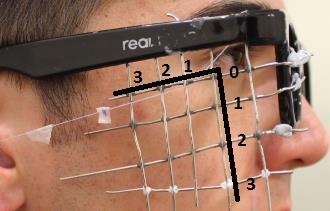
Comfort along various directions
It was expected that various closure directions would provide varying degrees of comfort. To test this, the string was passed through a grid prior to attachment to the actuator to constrain different directions.
The author graded the locations as most ideal, acceptable or uncomfortable. Ideal was defined as not noticeable, acceptable was defined as noticeable but not uncomfortable and unacceptable was defined as uncomfortable.
| 3 | 2 | 1 | 0 |
0 | unacceptable | unacceptable | unacceptable | acceptable |
1 | acceptable | ideal | ideal | acceptable |
2 | acceptable | ideal | acceptable | acceptable |
3 | Untested | Untested | acceptable | unacceptable |
The table coordinates correspond to the grid positions represented in the below Figure.
6mm displacement closure
Full closure could not be achieved without an uncomfortable level of pre-stress being applied to stretch the eyelid prior to actuator activation.
Test Method
1) Prepare electrical components
- The benchtop power supply should be tested with a potentiometer to ensure it is set at 10V.

Figure 3‑3: Benchtop power supply with push-button MAD controller attached.
- The power supply should be connected to the MAD controller through a good electrical connection
- The MAD controller should be connected to the actuator through a good electrical connection which is isolated and unable to contact human tissue.
2) Connect a string to the moving portion of the actuator.
- Tie a knot with the attachment string onto a cavity present on the metal surface of the moving component.
- Fix with the band-aid
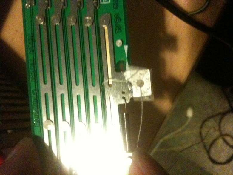
Figure 3‑4: Fixation of string to actuator using Band-Aid
3) Attach the string to the upper eyelid
- Wear the test glasses.
- Place a light amount of blu-tack onto the non-SMA containing (back) surface of the actuator.
- Lightly affix the actuator to some position on the glasses using the blu-tack, such that the attachment string on the actuator can easily reach the entirety of the upper eyelid. Take care to avoid excessively compressing the blu-tack, this will make the device more difficult to remove in subsequent steps.
- Prepare a cut, with approximately 2-3mm width and 10-15mm length, of transparent bandaid adhesive.
- Place the attachment string on the upper eyelid and affix it onto the lid using the clear bandaid adhesive. Take care that the “long side” of the bandaid follows the length of the string. Ensure that the string adheres to as much of the upper eyelid as possible.
4) Reposition the actuator so that the string is taut.
- Remove the actuator from the glasses, taking care to ensure that it still remains near the eyelid. Ensure that the blu-tack is still present on the back surface.
- Keep the eyelids fully open.
- While keeping the actuator near the handles of the glasses, increase its distance from the eyelid until the attachment string is taut.
i. Ensure that there is no stress on the eyelid in its fully “open” state.
ii. The line of action of the string to the eyelid should be approximately parallel to the horizontal plane of the body. This can be judged by whether the top of the actuator is approximately parallel to the handles of the glasses.
- Firmly affix the actuator to the glasses using blu-tack by compressing the blu-tack between the actuator and the glasses.
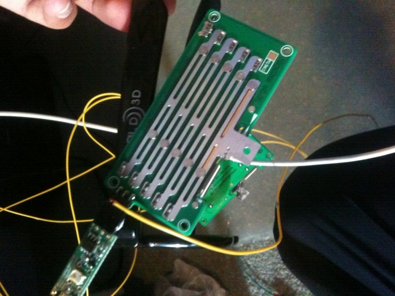
Figure 3‑5: Attachment of actuator to glasses.
5) Apply a voltage to the actuator to generate a closure motion.
- Press the button on the Miga Motors MAD controller to apply 10V from the standard bench top power supply.
6) Take note of effectiveness of closure
- Consider the degree of closure achieved. This can be measured through a visual approximation of the level of scleral exposure (in mm), or the rotation angle required to achieve closure (degrees).
- Consider other subjective factors based such as:
i. Adhesion or de-adhesion of the lid to the globe, based on visual observation or its “feeling”
ii. Any blurring of vision post-blink
iii. Comfort of the device (e.g. feelings of pre-stress) prior to the blink
iv. Overall feeling (comfort, similarity to natural blink) of closure motion
7) Adjust and repeat for different pre-stresses and lines of action
- The test has been carried out with conditions of no pre-stress and a horizontal line of action. The string was attached to the entirety of the eyelid. Repeat with
i. Increasing levels of prestress on the eyelid (corresponding to some degree of pre-closure due to the apparatus tension.
ii. Lines of action oriented at approximately 15, 30, 45 and 60 degrees to the horizontal.
iii. The string attached to only the lateral or nasal portions of the eyelid.
3. Evaluation of Device as per Design Specifications
Specifications
1) Full closure was achieved - this met specifications.
2) Closure was comfortable (or at least not uncomfortable) - this is considered to meet specifications.
3) The ease of use of the device does not meet specifications - it is difficult to take on and off and each application is not reproducible.
4) In terms of safety, the device does not meet specifications. While it is unlikely that damage will be caused during normal operation, it is unknown what harm will be caused during non-standard situations. For example - if the glasses fall off the user while being worn, there is potential for harm to the user (e.g. tissue damage).
Key future work involves:
1) Development of easy on/off mechanism (interface between glasses and patch system, also a simplification of the patch system) that can result in reproducible application of the device, within <30-60s, while also including a safety mechanism in case the glasses happen to be suddenly pulled off.
2) More reproducible and reliable fabrication processes and adhesive selection.
3) A systematic study outlining displacement ranges and comfortable position ranges required for the actuator displacement and constraint positions.
Obviously, integration of sensing and industrial design to include power and control in an ergonomic device are also required.
Summary:
In summary, the current device is unsuitable for patient usage and much work is required before it becomes viable. However, proof of concept has been demonstrated for a promising closure method which could form the basis of a device superior to current treatment methods for temporary lagopthalmos arising from facial nerve paralysis.