Soft Robotic Hand
Our project will be to create a soft robotic arm and hand using some of the pneumatic components from Soft Robotics Toolkit. The hand will be part of a larger system mounted on a remote controlled vehicle. The goal is to have a fully functional robotic arm and hand capable of picking up and manipulating an object near the vehicle. The entire system will be controlled remotely, including an onboard air system capable of supplying the necessary air to utilize the pneumatic components.
In the Background, we discuss the motivation behind the project. The world of robotics has been expanding into the realm of soft materials, and many new potential applications have arisen as a result. One such application is their use in a work area that could be dangerous or unsafe for people. This is the main driving force behind the project.
In the Design, we discuss the approach we took in coming up with ideas to make the project a reality. The Fabrication section shows how we went about building the robot itself and the potential issues we encountered along the way. Finally, we show the testing of the individual subsystems and the final integrated system in Testing.
The team working on this project is a Senior Design team at Rochester Institute of Technology. We are made up of mechanical engineers Travis Emery, Shehan Jayasekera, and Tim Kremers, biomedical engineer Andres Ulloa, electrical engineer Lucas Prilenski, and team guide Art North. The customer aiding and funding the project is RIT professor Dr. Lamkin-Kennard.
Background
Robotics is a field that is constantly pushing the boundaries on new technology. One of these new technologies is soft robotics. This field is dedicated to the science and engineering of soft materials in robotics. The project proposed here incorporates these concepts. Previous senior design projects at Rochester Institute of Technology have utilized air muscle technologies to create a functional robotic hand. This project will combine this new focus on soft robotics with the previously developed technologies in air muscle design to create an inflatable robotic hand. In addition to combining these technologies, this inflatable robotic hand will be mounted on an RC vehicle so that it can be mobile.
RIT professor Dr. Lamkin-Kennard has had a number of previous senior design teams create robotic hands controlled using artificial pneumatic muscles. They have varied with design specifics and use, but the use of soft robotics has been limited to just the muscles used to actuate the hands. Dr. Lamin-Kennards new vision was to create a fully inflatable system that utilizes soft robotics for the hand itself. The senior design team here was then employed to create such a system. This was the initial motivation behind the project, to expand more into the world of soft robotics and explore more potential capabilities.
One of the main problems this system is being designed to solve is how to work in a place that is unsafe for people. Of course there are other such system, like bomb disposal robots, that have provided solutions to this problem, but in the case where a softer touch is needed, the rigidity of previous robotic systems poses a problem. The system here could be a potential solution to this situation.
Design
The design process for this project was broken down into four different stages. First the customer requirements were attained through customer interviews, and these requirements were then translated into engineering requirements. A house of quality was used to ensure all the engineering requirements satisfied the customer requirements as well as any other requirements the team deemed necessary. This process is show in the Problem Definition. From there a functional decomposition was used to break down the project into its constituents. Benchmarking was performed to understand what current technologies were being used in similar applications. These technologies were combined in a morphological chart and then analyzed using a pugh chart to determine which combination of technologies would work best for our project. A feasibility analysis was performed to ensure all technologies would be applicable to our project. All of this is summarized in the System Design. From there, the project was broken down into three subsystems: Control, Navigation, and Force Actuation. Preliminary designs were worked up for each and a bill of materials was generated for the needed parts. This is shown in the Subsystem Design. The particulars of each subsystem were then designed and combined together to create out Detailed Design. This detailed design encompassed everything we planned on doing with this project. Although some modification were made as the project was built, the overall design remained fairly consistent.
Problem Definition & System Design
Team Vision for Problem Definition Phase
The project objectives were elaborated in detail to come up with a problem definition which satisfies all parties. Customer interviews were held, and engineering requirements were drafted. House of quality analysis was performed and use case scenarios were drafted.
Project Definition
An Inflatable Robotic Hand is a portable, mountable device that can inflate, manipulate an object, and deflate remotely. The system will be house in a container mounted on a RC car. This device will utilize some of the same principles, specifically the air muscles, used in previous RIT senior design projects P14253, P09023, P08023, and P08024. This project will add the ability of inflating out of a small container.
The goals of this project are to analyze previous air muscle designs, and other inflatable robot technologies, to identify an opportunity to combine these ideas into one product. The expected results is a functional prototype that can be applied to the task. The prototype must use air for generating actuation forces while resembling a hand with a minimum of three fingers.
Use Case

Project Goals & Key Deliverables
- The arm, hand, and vehicle can be remotely controlled by user
- Pick up a tennis ball
- Mounted on an RC vehicle
- Inflate out from a compartment
- Actuation force is produced by air muscles
Customer Requirements (Needs)
Purpose
To decompose the Problem Statement into functions of elements needed to satisfy the customer.
Customer Requirements
| Rqmt # | Importance | Description |
|---|---|---|
| C001 | 9 | Must use air for inflation and actuation forces |
| C002 | 9 | Must be able to pick up a tennis ball up to 2 in off the ground |
| C003 | 9 | Must resemble a hand or fingers |
| C004 | 9 | Must inflate from a container housed on an RC vehicle |
| C005 | 3 | Must deflate fully back into the container |
| C006 | 9 | Must be remote controlled |
| C007 | 9 | Material selection must withstand inflation/deflation cycles without popping or tearing |
| C008 | 3 | Use a single controller to control both the robotic arm and the RC vehicle |
| C009 | 3 | Prototype and final model must be built with a $750 budget |
| C010 | 3 | Move object (tennis ball) from one location to another |
| C011 | 1 | Mounted camera for targeting and navigation |
Inputs
- PRP
- Problem Statement
- Customer Interviews
- Art North & Dr. Lamkin-Kennard.
Outputs
Engineering Requirements (Metrics & Specifications)
Purpose
Create a contract between the engineer and the customer where indisputable satisfaction of the engineering requirements equates to customer satisfaction
Engineering Requirements:
| Rqmt # | Importance | Engineering Requirement | Unit | Target Value | Marginal Value |
|---|---|---|---|---|---|
| 001 | 1 | Air compressor power | psi | > 120 | 100 |
| 002 | 9 | Air compressor flow rate | scfm | > 0.88 | 0.3 |
| 003 | 9 | Inflation time | sec | < 2 | 5 |
| 004 | 3 | Deflation time | sec | < 10 | 15 |
| 005 | 3 | Inflation arm reach | in | > 6 | 4 |
| 006 | 1 | Object lift distance | in | > 6 | 4 |
| 007 | 9 | Hand grip strength | psi | > 20 | 15 |
| 008 | 3 | Stored air volume | ml | > 1200 | 200 |
| 009 | 3 | Stored air pressure | psi | < 100 | 80 |
| 010 | 9 | Number of fingers on robotic hand | units | = 3 | 3 |
| 011 | 9 | Battery life | min | > 90 | 30 |
| 012 | 3 | Chassis load weight capacity | lb | < 40 | 120 |
| 013 | 9 | Chassis surface mount area | in^2 | < 24x24 | 30x30 |
| 014 | 3 | Arm container cross-sectional area | in^2 | < 6x6 | 8x8 |
| 015 | 1 | Arm container height | in | < 8 | 10 |
Inputs and Source
- PRP
- Dr. Lamkin-Kennard
- Art North
Outputs and Destination
- HoQ
Constraints
From Customer Requirements
- Inflation mechanism must use air only
- Robotic arm and hand must fit inside a small container
From Engineering Requirements
- Weight of robotic arm, air compressor, tank, and control systems must not exceed chassis weight capacity
- Must have large enough power source to supply power to the motors, compressors, and control systems
House of Quality
Inputs and Source
- PRP
- Customer Requirements
- Engineering Requirements
- Benchmarking Data
Outputs and Destination
Design phase
Team Vision for System-Level Design Phase
Our plan was to develop the functional decomposition of our system, come up with possible solutions, and out line the system architecture. We also planned on benchmarking the different components and analyzing the feasibility.
We were able to complete all of the tasks we set forth to do for this phase.
Functional Decomposition
Benchmarking
Morphological Chart and Concept Development
Concept Selection
Concept Selection & Pugh Chart
Systems Architecture
Feasibility: Prototyping, Analysis, Simulation
Risk Assessment
Subsystem Design
Team Vision for Subsystem-Level Design Phase
Our primary objective in this phase was to prototype and analyze our 3 subsystems which were the Control, Navigation, and Force Actuation. For each subsystem, we came up with different proof-of-concepts for different designs, which we then benchmarked and chose the best design to move forward with.
Control: H-bridge, Motor drivers, Solenoid drivers,
Navigation: Motors, Chassis, Wheels, Gearbox, BOM
Force Actuation: Solenoid valves, Flow loop design, Arm designs, Hand, BOM
Sub-Subsystem Design & Engineering Requirements
Feasibility: Prototyping, Analysis, Simulation
Control:
Micro-controller:
- considered PWM requirements
- MSP430
Peripherals:
Power Regulators:
Navigation:
Locomotion:
- motors
- CIM
- Pololu 100:1 gear motor
- wheels
- Pololu wheels
- gearbox
- frame (2ft x 2ft)
Force Actuation:
Arm:
- 2 arm designs considered
- 4 Channel Arm (4ChA)
- Slinky Arm (SA)
- preliminary prototyping of 4 Channel Arm (4ChA)
Finger:
- 1 finger design considered
- PneuNets Bending Actuator (PNBA)
- preliminary prototyping of PNBA has begun
- prototype part made
Pressure Distribution:
- Flow loop designed (schematic below)
Inputs and Source
- Engineering Requirements
- Concept Selection
- System Architecture
Outputs and Destination
- A list of Design Parameters, Quantified Targets, and acceptable tolerances
- Sensitivity analysis
- Concept Selection
Drawings, Schematics, Flow Charts, etc.
Air System Schematic
- A, B, C, D, E - one-way solenoid valves
- F - two-way solenoid valve
Valve Positioning:
- 1 (power on - valve closed)
- 0 (power off - valve open)
| Valves | ||||||
|---|---|---|---|---|---|---|
| Task | A | B | C | D | E | F |
| Tank Fill | 0 | 0 | 0 | 1 | 0 | 0 |
| Arm Inflation | 0 | 1 | 0 | 0 | 1 | 0 |
| Finger Inflation | 0 | 1 | 1 | 0 | 0 | 0 |
| Finger Deflation | 1 | 0 | 1 | 1 | 0 | 1 |
| Arm Deflation | 1 | 0 | 0 | 1 | 1 | 1 |
| Pressure Release | 0 | 0 | 0 | 1 | 0 | 0 |
Bill of Materials (BOM)
Navigation:
| QTY | Description | Supplier | Cost ($) |
|---|---|---|---|
| ----- | ------------Structural------------ | ------------ | ---------- |
| 6 | 30” Aluminum C-Channel | Andymark | $18/ea |
| 8 | C-Base Aluminum Corner | Andymark | $4/ea |
| 42 | ¼” - 20 Hex Head Bolts | N/A | $14 |
| ----- | ------------Locomotion------------ | ------------ | ---------- |
| 2 | 2.5” CIM Motor | Andymark | $28/ea |
| 2 | Toughbox 14.88:1 Gear Box | Andymark | $75/ea |
| 4 | 4” Rubber Treaded Wheel | Andymark | $4/ea |
| 2 | ½” x 4” Free Axle | N/A | N/A |
| 2 | Direct Drive Collar | N/A | N/A |
| 2 | 3’ Drive Chain | N/A | N/A |
| 2 | Sprockets for Chain Drive | N/A | N/A |
Air System:
| QTY | Description | Supplier | Cost per Part($) | Link |
|---|---|---|---|---|
| 1 | Compressor | AndyMark | 69.00 | Link |
| 1 | Check Valve | McMaster | 17.03 | Link |
| 2 | Air Tank | AndyMark | 16.00 | Link |
| 8 | 1-Way Solenoid Valve | RIT | 0 | N/A |
| 1 | 2-way Soleniod Valve | RIT | 0 | N/A |
| 17 | Soleniod Valve Connector | RIT | 0 | N/A |
| 2 | Pressure Regulator | RIT | 0 | N/A |
| 2 | 2-Outlet Manifold | McMaster | 22.94 | Link |
| 6 | 1/4" NPT Compression Fitting | McMaster | 1.35 | Link |
| 4 | 1/8" NPT Compression Fitting | McMaster | 1.30 | Link |
| 25 ft. | 1/4" OD Polyethylene Tubing | McMaster | 0.10 per foot | Link |
| 25 ft. | 1/8" OD Polyethylene Tubing | McMaster | 0.05 per foot | Link |
Risk Assessment
Detailed Design
Team Vision for Detailed Design Phase
Our primary objectives for this phase were to:
- Update test plans
- Control: motor and solenoid drivers, power supplies, controller mapping, transmission range
- Navigation: motor/robot movement speed, battery life, frame weight and size
- Force Actuation: mock flow loop, arm and finger
- Acquire remaining parts necessary for test plans
- Update schematics and flow charts for each subsystem
- Come up with team and individual plans for MSD II
- Prepare for the gate review
Detailed Design Phase To-Do List
Prototyping, Engineering Analysis, Simulation
The following subsystems will be prototyped:
Control System
Solenoid Drivers
Force Actuation System
Arm
Fingers
Mock Flow Loop
Drawings, Schematics, Flow Charts, Simulations
Control System
Motor Driver:
Motor Driver Documentation
Power Supply:
5V Power Supply Documentation
24V Power Supply Documentation
Solenoid Driver:
Drive System
Priming of Air Flow System
Arm and Finger System
Controls Preliminary Code: Xbox controller Arduino code
Controls Risk Management: Bad User Input
Navigation System
Feasibility: Torque Analysis
Full Model Assembly:
Base Model Assembly:
Upper Model Assembly:
Force Actuation System
Feasibility: Air System
Detailed Flow Loop:
Mock Flow Loop:
Bill of Material (BOM)
We consolidated the BOM of each subsystem into one: Total BOM
Test Plans
Control System
Navigation System
Force Actuation System
Design and Flowcharts
Updated System Architecture
3 Subsystems:
- Control System
- Navigation System
- Force Actuation System
Risk Assessment
Fabrication
With the design of the project complete, all materials from the Total BOM were purchased to begin fabrication. Each of the five members focused on a single aspect of the project. These five aspects were control, power, navigation, air flow, and object manipulation. In the Subsystem Fabrication, each of these were created individually and tested individually. Once the individual testing was complete, the systems were combined piece by piece in the Integrated System Fabrication. Initially just the air air flow, power, and control system were combined. Once these were mostly working, the object manipulation system was integrated into the build. Extensive testing was done at this point to optimize the performance of the robot through various means. Finally, the navigation system was incorporated into the build to create the final product in Final Fabrication.
Subsystem Fabrication
Object Manipulation System
The object manipulation system contained two primary components: the arm and the fingers. As such, the fabrication was divided into each of these.
Arm
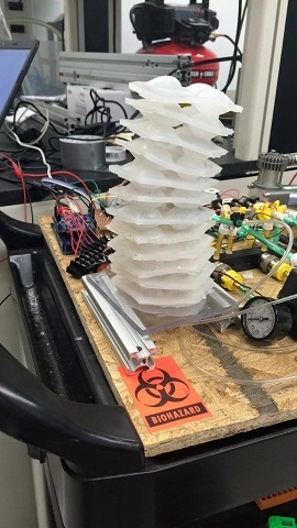
The arm consisted of a 4 channel design as shown in the subsystem design section. The process was very similar to another soft robot shown here. First a mold was created out of acrylic so that a liquid epoxy could be poured into it. The mold was made up of three layers of 6"x6"x1/16" acrylic glued together. The top layer had a hexagon with 2" sides cut out of the center. The middle layer had 4 1/2" diameter through holes where the layers would connect to one another and also had square holes cut out along the edges of the hexagon to act as standoffs. The bottom layer was solid. A fourth piece of acrylic was also cut with the same hexagonal shape in the center as the third layer, but not glued to the other three layers to simplify the building process. The mold can be seen here.
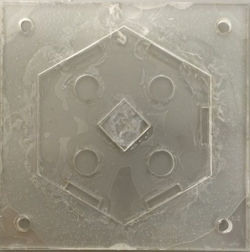
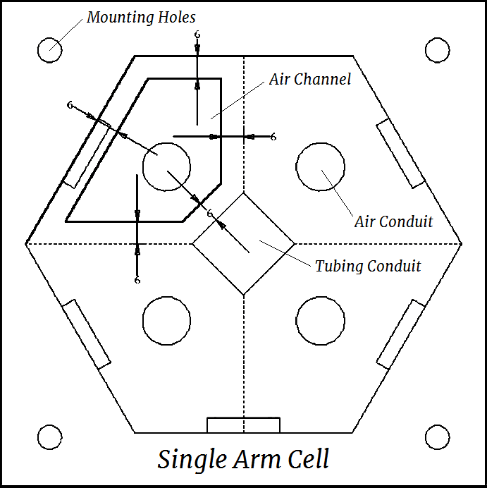
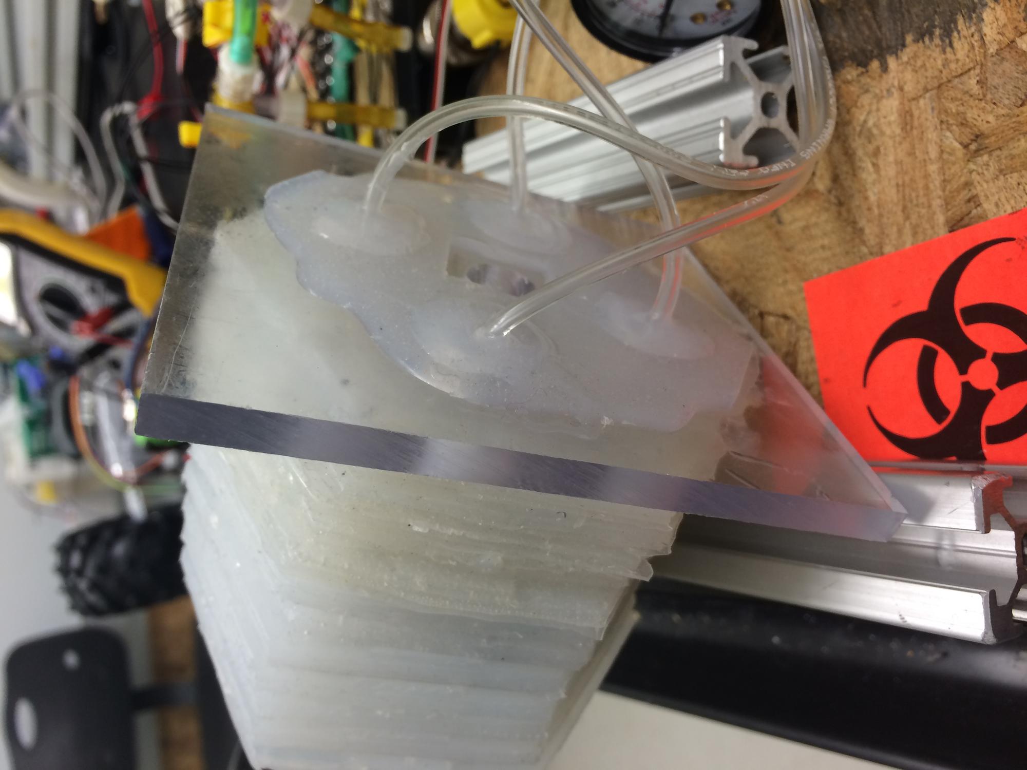
A two part epoxy was used to create the arm. Smooth-on Dragon Skin 10 was used with a Silicone Thinner. The thinner was only used to make the upper arm layers because the decrease the strength of the material and it was found that the lower layers needed to be stronger to withstand the strain caused by actuating the arm. The bottom five layer of the arm did not use the thinner. The upper layers used the thinner to help remove air bubbles which were common failure points in testing. The epoxy and thinner was mixed and then put into a vacuum chamber to remove all the air bubbles from the mixture. It was then poured slowly into the mold so no air bubbles were created. Plastic grocery bags were then cut into shape to create the four air pockets in the arm. Since the epoxy would not stick to the plastic bags, the pocket would inflate when pressurized with air. The shape can be seen in the image directly above. Approximately 6mm of space was left between the edges or center lines and the cavity edge. More epoxy was then mixed, the fourth layer of acrylic was placed over the mold, and the upper layer of epoxy was poured in. The epoxy cured in roughly 30 minutes. They layer could then be removed and holes were drilled through the layer where it would connect to the layers above and below it. A square hole was also cut in the center of each layer. This process was repeated to create 12 layers. To attach each layer to one another, a small amount of epoxy was place on the circular connecting pads and the layers were placed on top of one another. Once dry, four holes were drilled to create four continuous channels running the length of the arm. The bottom layer was attach to a 1/2" piece of plastic by drilling four holes in the plastic where the 1/2" diameter standoffs protruded from the bottom layer. More epoxy was used to secure the layer to the plastic base. Tubing was inserted into each of the four channels and glued with epoxy to later be connected to the flow system. This can be seen in the image below.
Fingers
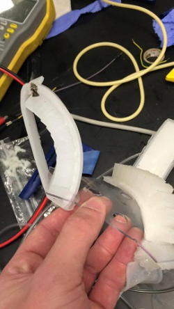
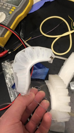
The PneuNets Bending Actuator was used to create the fingers. The molds were 3D printed and the process that is outlined on the website was used to create three fingers. The same Dragon Skin 10 material was used to create the fingers. The mold used can be seen below. Plastic tubing was then inserted into one end of the finger and glued using epoxy to later be attached to the flow system.
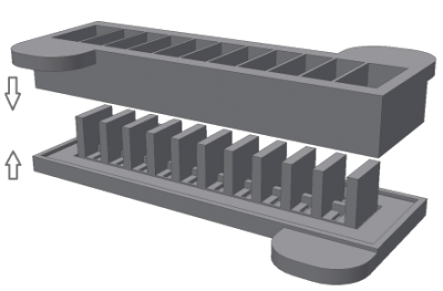
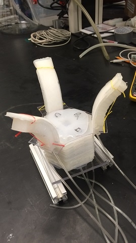
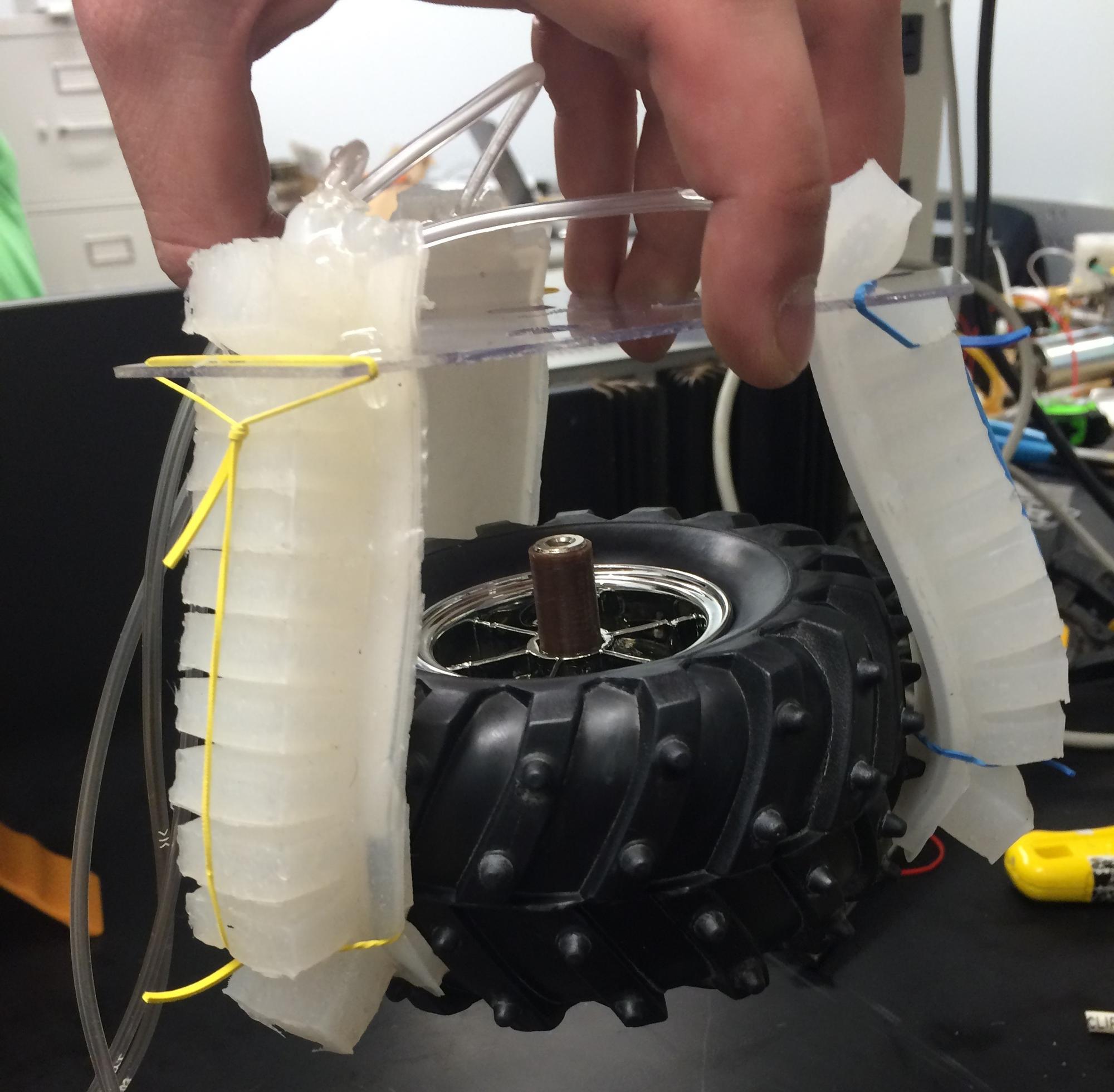
A 1/16" piece of plastic was cut into a hexagonal shape with extra room left on three of the six sides to mount the fingers. An image of the mounted fingers can be seen below. The three air lines from the fingers were tied into one so all the fingers would actuate at the same time. Rubber bands were attached to the fingers and finger base to keep them from falling inward during use.
The base of the fingers was then attached to the top layer of the arm using the same epoxy. The final product can be seen below.
Air Flow System
The air flow system was built on a 18"x24"x1/2" piece of plywood. The following schematic was used as the design for the flow system. Each part was held down to the plywood using bolts or zip ties wrapped through holes drilled in the plywood.
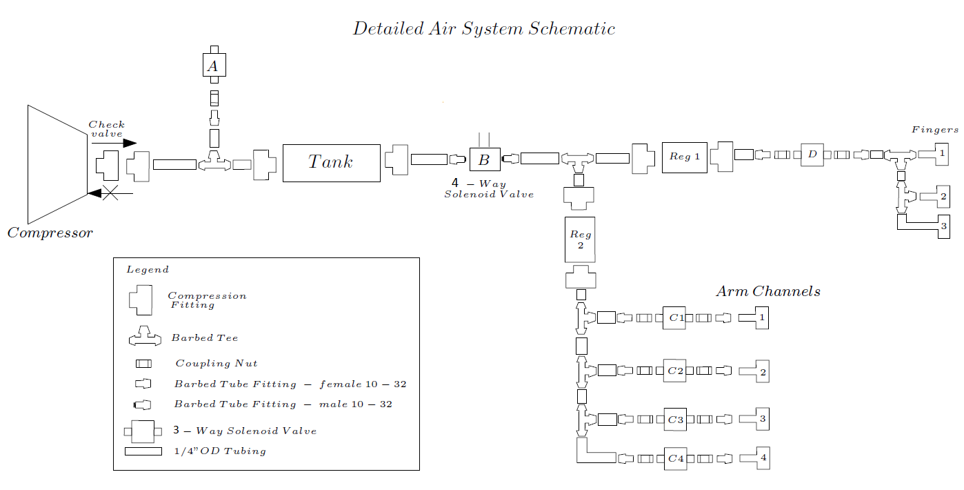
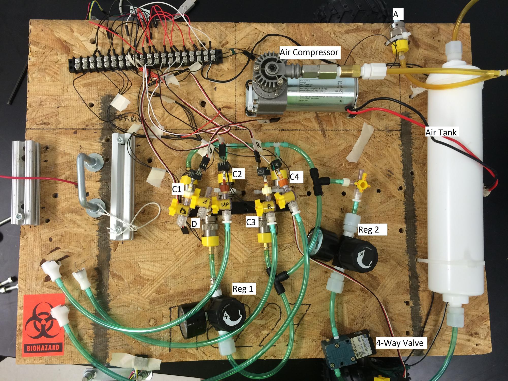
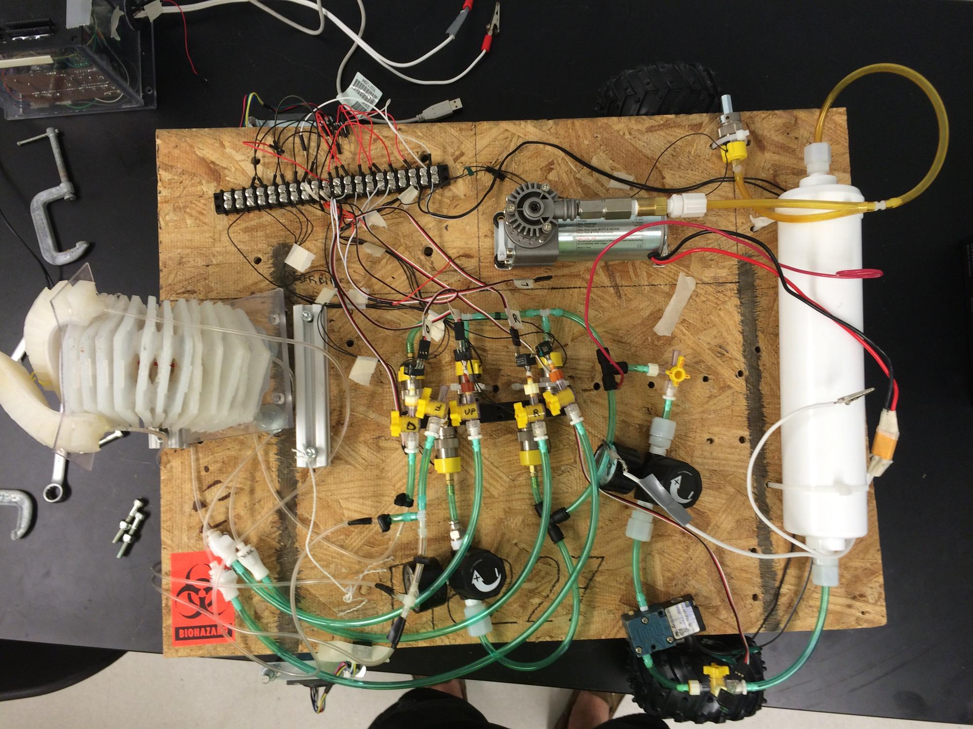
The final test loop was very similar to what is shown above with just a few small changes. For space saving reasons, the line split to the fingers was made after regulator 2 instead of before. Since the fingers were expected to operate at a much lower pressure than the fingers, this would not cause any issues. The other change was that solenoid valves C1-C4 and D were all tied into a manifold. This was down because the type of solenoid valves used here required a manifold to work properly. Those solenoid valves were also modified so no air could escape through the exhaust. If this modification had not been made, any compressed air in the arm or fingers would be released to the atmosphere when the valve was closed and the hand would not have been able to maintain a stationary position when pressurized. Teflon tape was used to seal any threaded connections to prevent air leaks. Compression fittings were also used when possible to prevent air leaks and ensure no connections would come loose at higher pressures. Additionally, a pressure feedback system was also added. Six pressure transducers were added into the system to relay pressure information to the control system. One transducer for each arm channel, one for the finers, and one for the tank were installed. The final flow loop can be seen below.
Control System
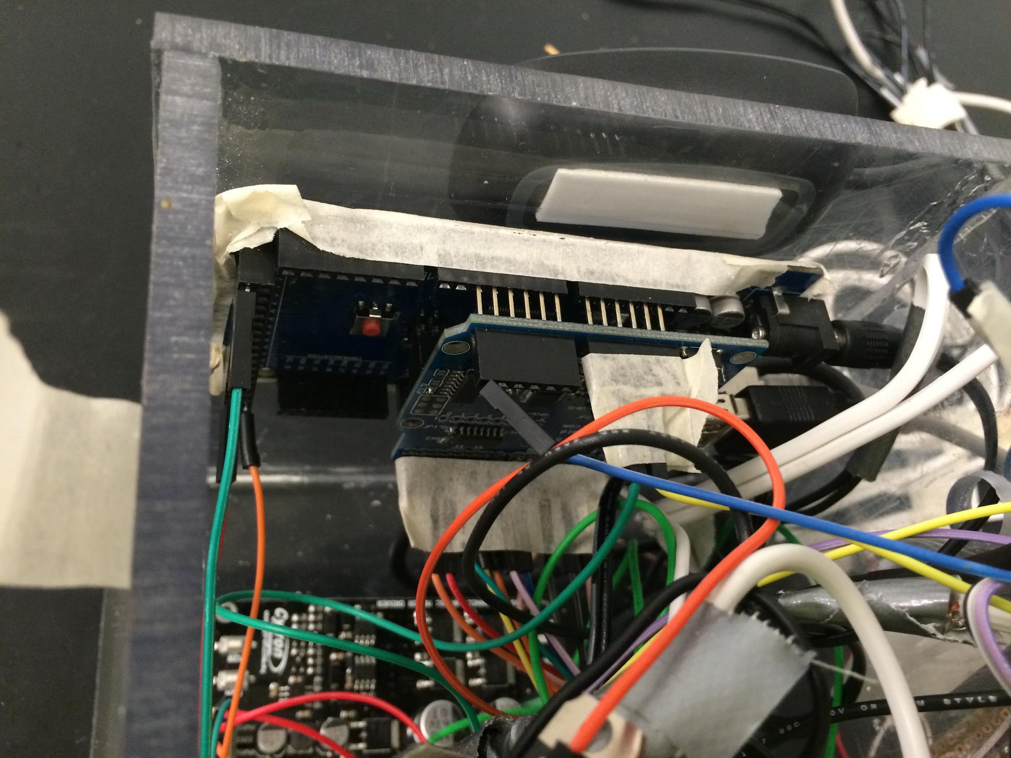
A USB Host shield is used to interface the Arduino Mega 2560 and the gaming receiver. A wireless Microsoft Xbox 360 remote controller is used to control the outputs from the arduino. The controls mapping is shown in the table below.
Button | Function |
Left Trigger (LT) | Drive Forward |
Right Trigger (RT) | Drive Backwards |
Left Joystick | Drive Steering |
D-Pad | Select Arm Direction |
A | Inflate Selected Channel |
B | Deflate Selected Channel |
Start | Inflate All Channels |
B + Start | Deflate All Channels |
Y | Inflate (Close) Fingers |
B + Y | Deflate (Open) Fingers |
Back | Activate Compressor |
Some automated control were also built into the controls as well. These incorporated the pressure feedback from the air flow loop. Their controls and function are shown in the table below.
Control | Limits | Action |
System Air Pressure Fail Safe | 100 psi | If pressure exceeds upper limit Release Valve A is opened to lower the system air pressure. |
Operating Pressure Control | 20 psi | If pressure drops below the limit during operation the compressor is turned on in order to maintain pressure at operating levels. |
Arm Pressure Control | Calibrated for each channel; nominally 2 psi | Each channel has variation in structure due to an imperfect fabrication system. This variation leads to each channel having a different movement response for any arbitrary pressure. To control this the pressure limits in each channel are calibrated in order to ensure full inflation leads to a completely vertical movement response. |
Arm Pressure Fail Safe | 2 psi | In case of a malfunction of a pressure sensor if any channel reaches 2 psi the valves will close for all channels. |
All software was developed in the Arduino IDE and written in Arduino C++.It runs a main loop which calls subsystem functions. The program is broken into subroutines that handle the different aspects of the robot. The code can be found here.
Navigation System
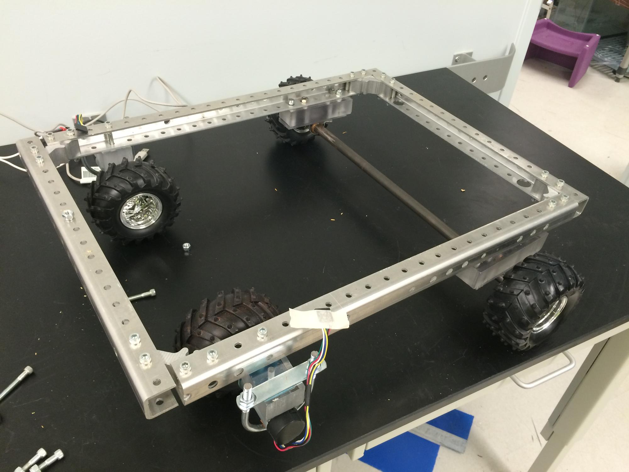
The navigation system consisted of a 18"x24" frame made of 80/20. The motors were mount on L-Brackets and then attached to plastic spacers which were attached to the frame using 1/4" bolts. The wheels were attached directly to the motors. The motorized wheels were placed at the front of the frame to make it front wheel drive. Since there was no built in turning capabilities, the hope was that a front wheel drive system might allow turning my spinning only a single wheel at a time. The back wheels were rigidly attached to an axle that was mounted to the frame using pillow blocks. Spacers were also used between the pillow blocks and frame to ensure the wheels had enough clearance and the frame would sit level with the ground. A picture of the complete frame can be seen below.
Power System
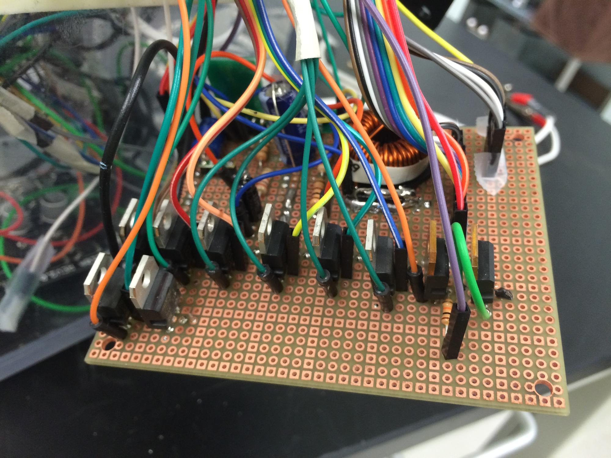
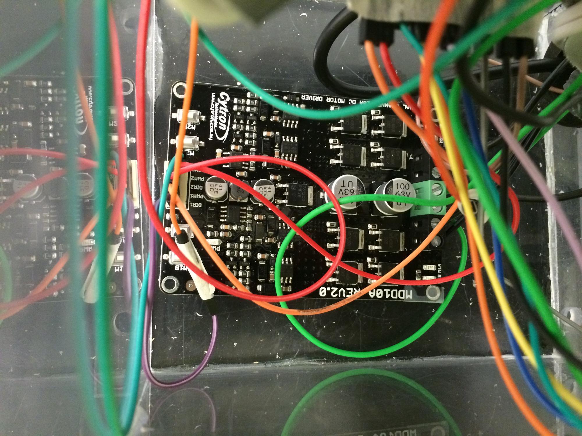
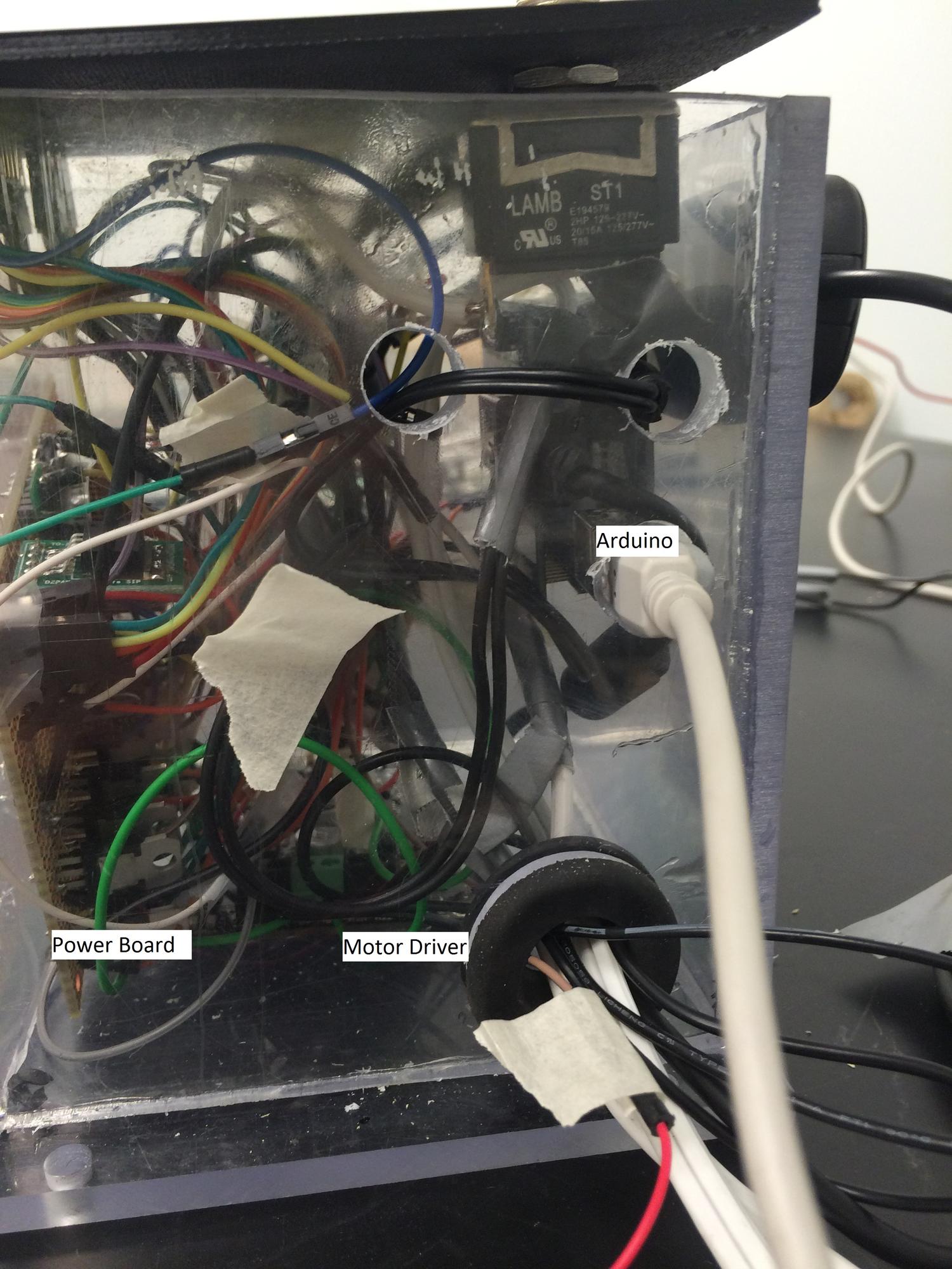
A custom board was made for the power system as outlined in the detailed design section. A 12V 18Ah lead acid battery would be used as the main power supply. The compressor and 4-way solenoid valve could both be run directly off this. The motors were also 12V but required 5A of current which is more than the arduino can supply, so a Cytron MDD10A was used as a dedicated motor control board. The board was still capable of being controlled by the Arduino. The 3-way solenoid valves used 24 volts and the the Arduino and pressure transducers used 5 volts. The input voltage from the battery was regulated to accommodate this using a boost converter circuit. MOSFETs were placed between the drain of the solenoid valves and compressor and the ground. The output from the Arduino was used to control the MOSFETs and actuate the each solenoid valves or compressor. The circuit boards can be seen below.
Boost Converter Circuit and MOSFETs:
Cytron MDD10A Board:
Arduino with Shield, and gaming receiver behind:
Integrated System Fabrication
Once all the subsystems were created, integrating them together was just a matter of making all the connection. The following process was used to do so.
Object Manipulation and Air Flow Loop
Simple T-Connectors with detachable fittings were used to split each outlet from the manifold to the pressure sensor and the arm or fingers. Barbed quick connectors were used to connect the 1/4" tubing leaving the manifold to the 1/16" tubing leaving the fingers and arms. The quick connectors allowed for easy removal of the arm in case any repairs were needed. The base of the arm was attach to a hinge and the hinge to a 1" x 1" piece of 80/20. The 80/20 was then attached to the plywood board. A square u-bolt was placed underneath the base of arm and secured using nuts. The height of this u-bolt could be adjusted so that the arm could sit flat or at an incline. The wires from each solenoid valve and the pressure sensors were all connected to a single rail to better organize the system. The wiring for the compressor and motors were kept separate as they would draw much more current than the valves and transducers and would require larger gauge wire.
Electrical Consolidation
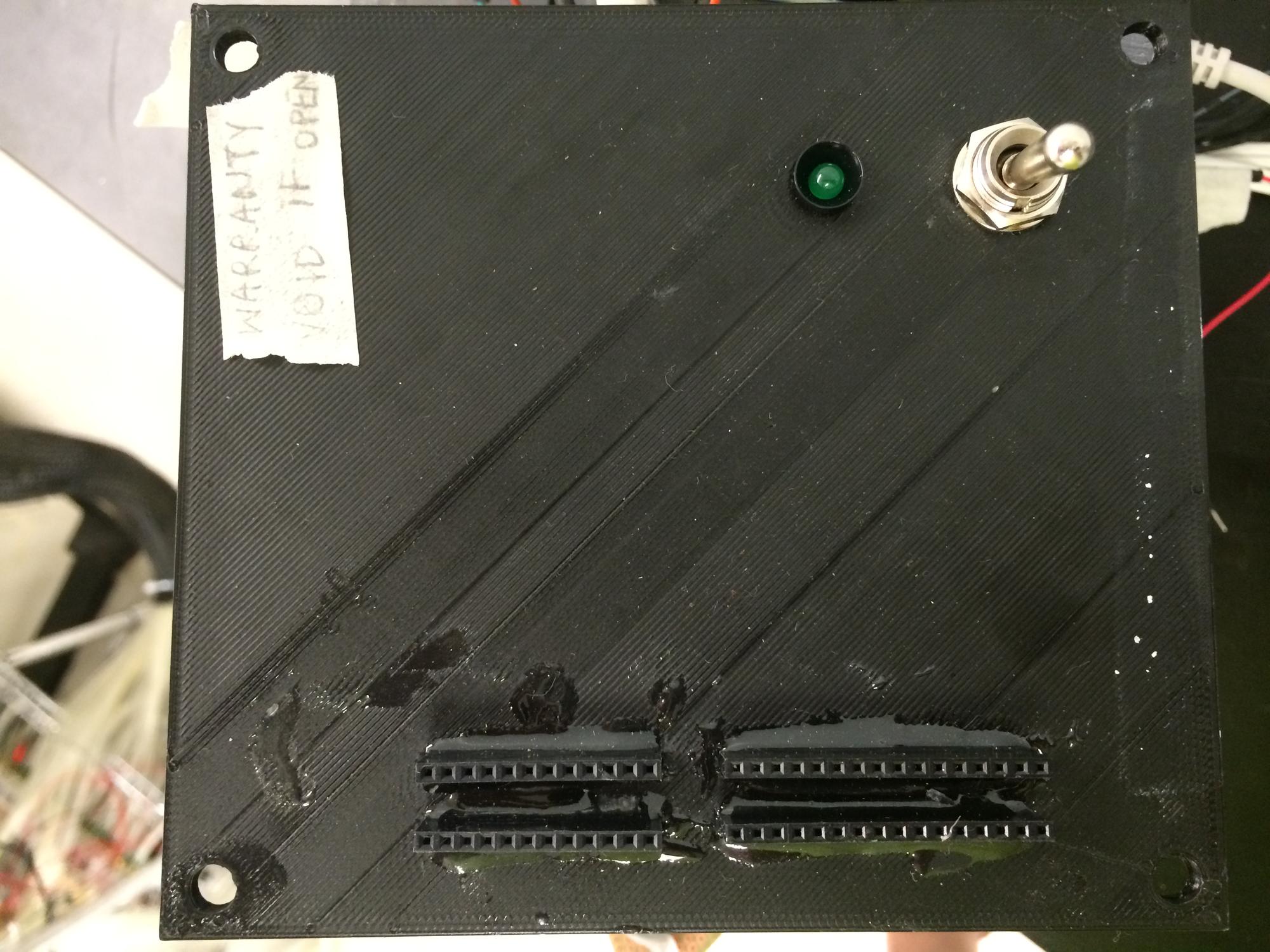
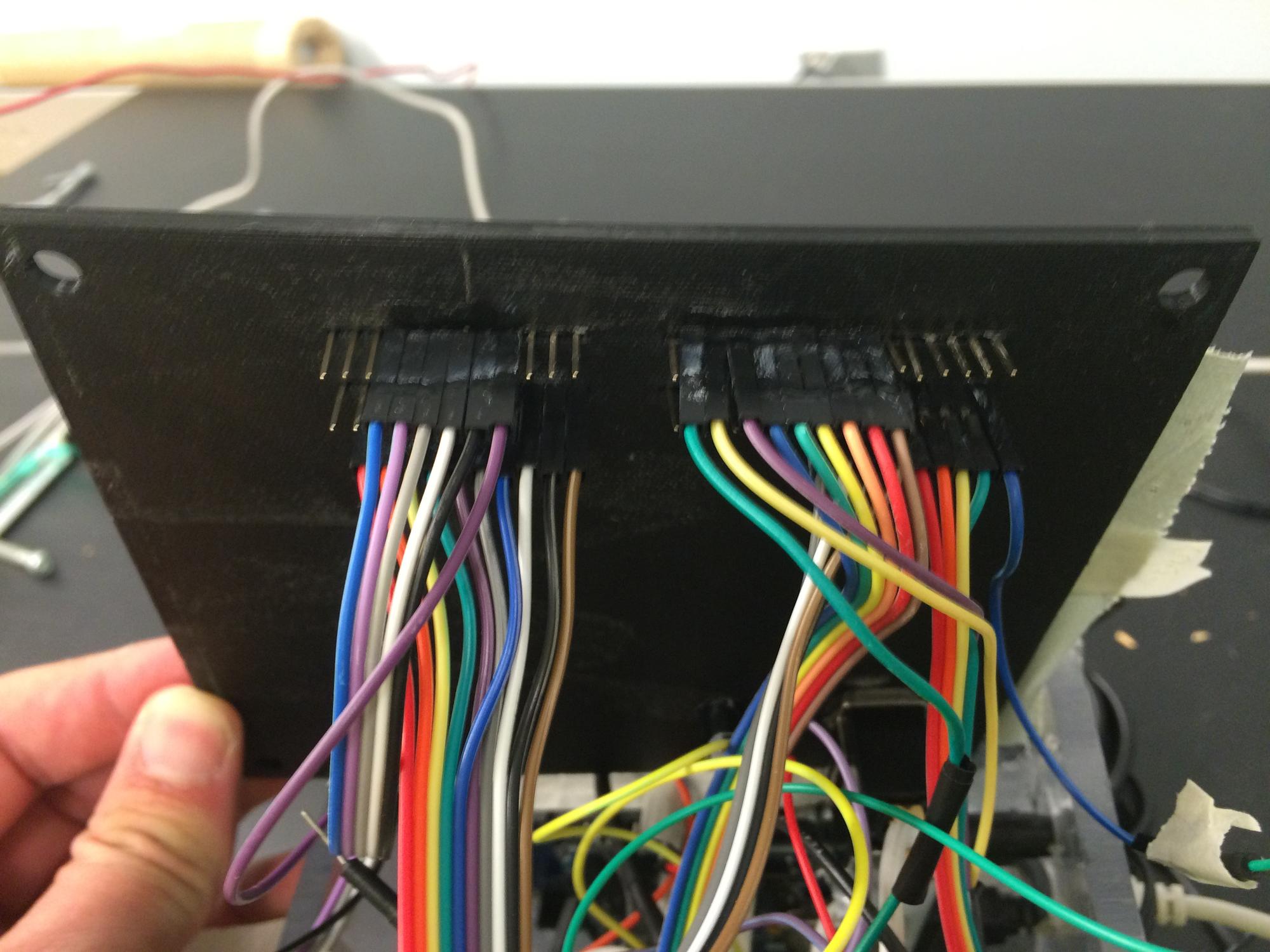
In order to protect the circuit boards, a box was made from acrylic to house them all. A lid was 3D printed to allow for a switch to turn the system on and off as well as to allow for headers to connect the solenoid valves and pressure transducers to their appropriate connection. The headers also had ground, 5V, 12V, and 24V outputs for accessories. Holes were made on the side of the box as shown below to allow for connections to the gaming receiver, the battery, the compressor and the motors. Again, since those components drew much larger currents they could not be run through the headers on the top. A hole was also made to attach the USB connector from the Arduino to a computer to make any updates necessary without having to remove the Arduino from the box.
Final Fabrication
Flow Loop, Object Manipulation, Power, and Controls
The electronics box was mounted on the board next to the compressor using 1/4" bolts to secure it to the plywood. The electrical rail from the flow loop was attached to the side of the electronics box and the connections were made to the appropriate headers. The battery was placed at next to the air tank near the center of the board to try to evenly distribute the weight. Alligator clips were used to attach the power board to the battery so it could easily be replaced if the battery dies.
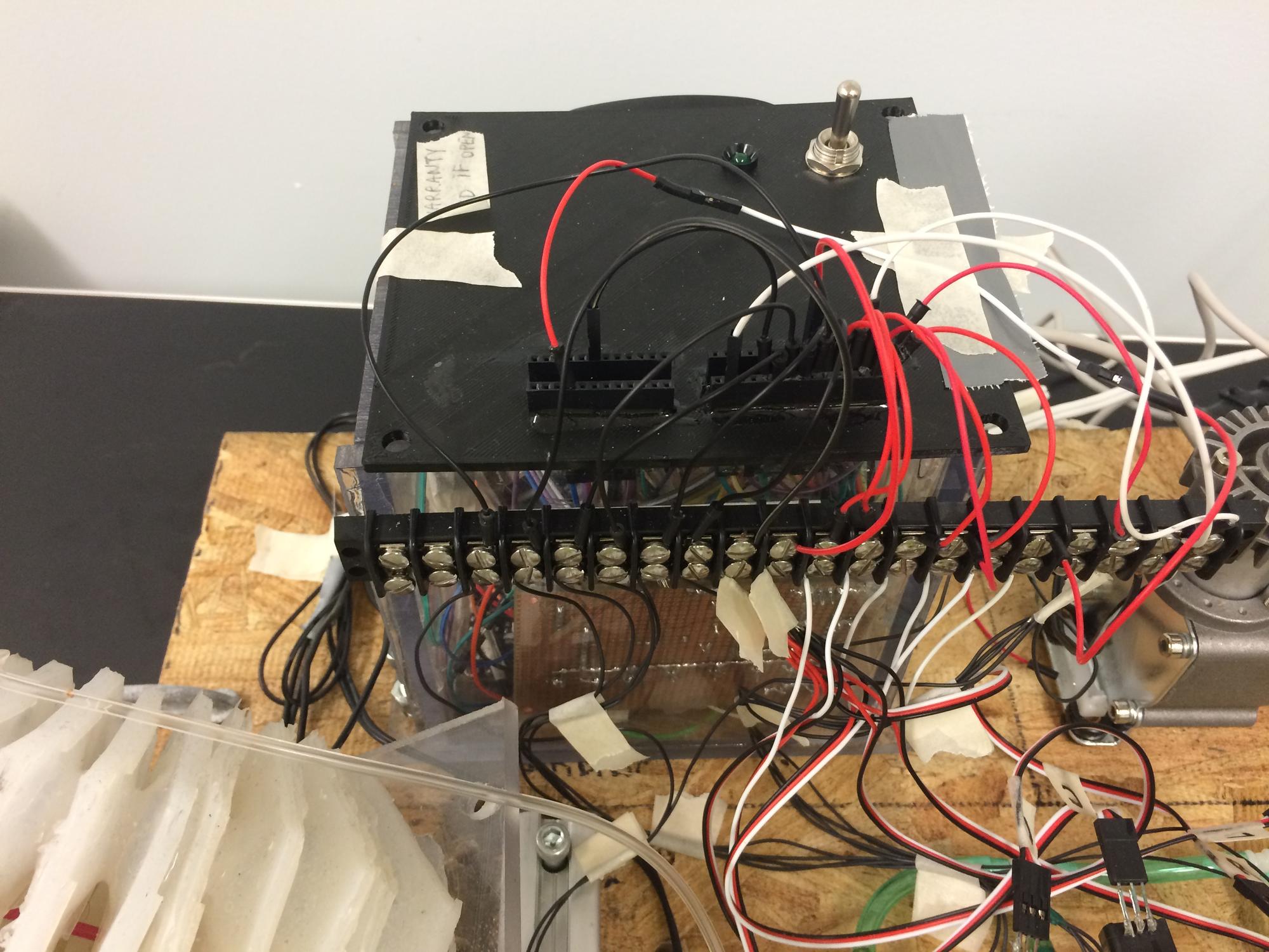
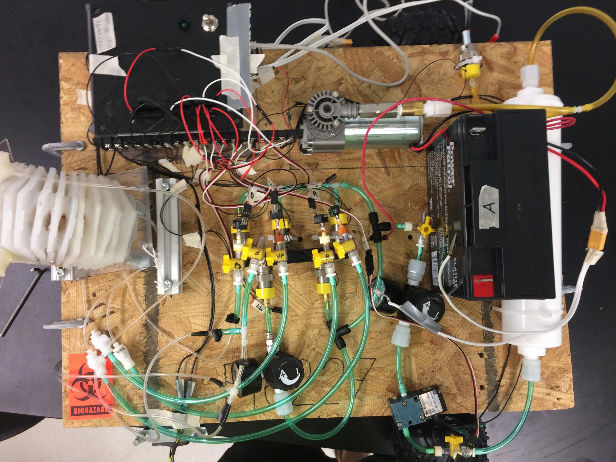
Navigation System Integration
The final part to assemble the project was to attach the plywood board to the frame. This was done using C-clamps. This was done so the board could easily be removed to make any frame repairs. Once finalized, bolts could be used to secure the plywood to the frame more permanently. The wires for the motors were attached and secured to the plywood to complete the build. The final product of the build can be seen below.
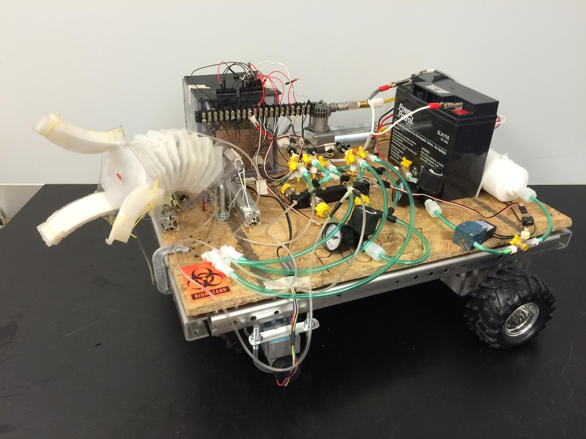
Testing
Testing was performed initially on each subsystem to ensure each part of the system was working as desired. From there, the systems were combined an tested. First the controls were integrated with the power system and tested. The flow loop was then integrated into testing, followed by the object manipulation system, and finally the navigation system. The details of the testing can be found in the subsequent pages.
Subsystem Testing
Object Manipulation System
Arm testing
Once a few layers of the arm were created they were testing using a lab air supply to measure the inflation time, deflation time, and how much each layer would expand. An external air compressor was used to inflate each channel individually by manually opening the flow paths to each arm channel. The final number of layer was then determined based of the expansion size to allow for the desired reach. The necessary air pressure to operate the arms was also determined. In testing, it was discovered that the lower layers would expand to their maximum capacity before the upper layers would fully inflate. To compensate for this, the silicone thinner was only used in the upper layers since it reduced to strength of the material. Doing so allowed for a more uniform inflation of the arm. Directional control was also tested to ensure this method would work as intended.
Finger Testing
Testing using the external air compressor was also performed on the finger to determine inflation time, deflation time, and maximum pressure. It was also used to determine the strength of the fingers when inflated. Once of the tires was used as a test object to ensure the fingers were strong enough to grasp a tennis ball.

Air Flow System
Once built, the air flow system was tested using an external air compressor. First testing was done to find any leaks. Soapy water was applied to all connection to determine if air was leaking from the connection. Any holes found were sealed closed. Each solenoid valve was tested using a DC power supply to open and close them when under pressure. The compressor was also tested to determine how long it would take to inflate the tank. The compressor was able to pressurize the air tank to 100 psi in under 30 seconds. Each part of the system was also tested at incrementally higher pressure to determine all connection were stable, even when pressurized beyond what the expected pressure would be. The entire system was tested up to 100 psi. The pressure transducers put out an analog voltage based on the pressure. A correlation between applied pressure and output voltage was created to later be used in the controls.
Control System
The controls for the system was tested as the subsystem were combined. Initial testing was performed to ensure the output voltages from the Arduino were functioning properly when connected to the gaming controller. Once the power system was complete, the outputs from the power system were checked to ensure they were functioning properly. Once combined with the flow loop and navigation systems, the functions were continuously tested to work out any bugs.
Navigation System
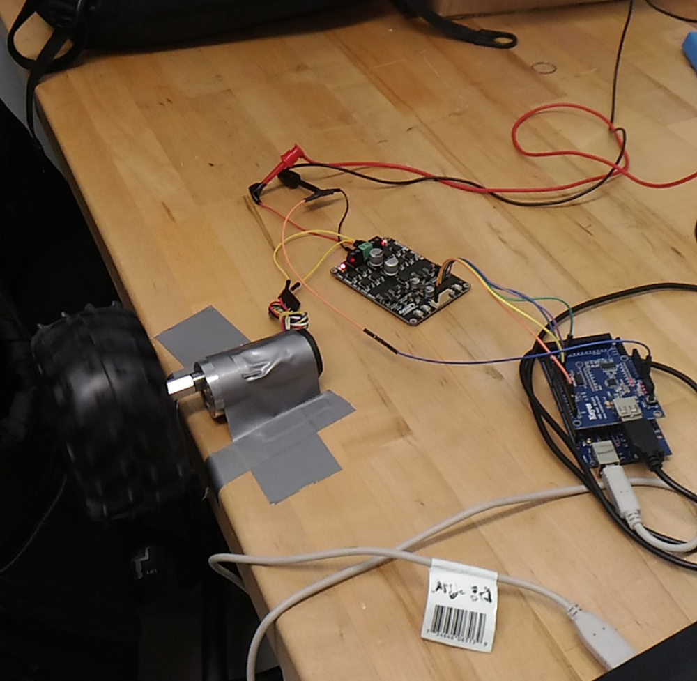
To test the navigation system, the motors were first hooked up to the driver board and the Arduino. Directional and speed control were tested to ensure proper functionality. Most testing on the navigation system occurred later once it was integrated into the rest of the system.
Power System
The circuit was first testing using Texas Instruments Webench design center. Once built the circuit was tested using a DC power supply and a multimeter to test the performance. Once integrated with the control, the MOSFET testing was also performed to ensure the functioned as required.
Integrated System Testing
Power and Control Systems
The power and control systems were integrated first since they work so closely with one another. A DC power supply was used to power the circuitry while testing. The gaming controller was operated while a multimeter was used to measure the output from the power board. Each function was tested and any issues were identified and corrected in this manner. Once it was confirmed that the controls were outputting the expected response, the power and control systems were integrated with the other subsystems.
Flow Loop, Power, and Controls
The power and controls were then integrated into the flow loop. The loop was pressurized using an external air compressor and then actuated using the various controls. Power loss testing was also performed to ensure the system would operate safely in the occurrence of sudden power loss. Since the tank was operating at much higher pressures than the arm or finger and the solenoid valves were normally open valves, it needed to be ensured that power loss would not cause the arm and fingers to rapidly inflate. To ensure this, the 4-way valve was setup so that in the even of a power loss, the arm and fingers would not be connected to the air tank. Instead both would release to the atmosphere. The next testing was performed to make use of the pressure transducers. The transducer were used as a feedback system to close off the solenoid valve if the pressure transducer reached a critical pressure. Doing so also allowed the pressure regulators to be used as a means of controlling the flow rate into the arm and fingers and the sensors to be used as a means of ensuring the arm and fingers weren't over-pressurized. The pressure transducer attached to the air tank was also used as a regulation system. Once the sensor reach 100psi, the compressor could be automatically turned off. Once it reach a minimum pressure it could also be turned on. Precautions were taken when programming the controls to ensure the arm and fingers could not be actuated when the compressor was running.
Object Manipulation Integration
Once the flow loop, controls, and power systems were combined, the object manipulation could also be integrated. Once the arm and fingers were mounted and the air tubes connected, the reach and strength of the arm was tested. An issue was found during testing in that the fingers made the arm top heavy and thus difficult to control. To overcome this, a 14 gauge solid copper wire was run down the center of the arm. The wire provided the added support needed to keep the arm upright when extended.
Final Testing
Once the navigation system was integrated, final testing was performed. This was done by simply operating all the controls as and determining the functionality of the robot. There were a few issues found during this final testing. The first issue was that the compressor would work once and then be on constantly even when not being controlled to do so. The issue found was that the high current spikes when turning the compressor on and off was burning out the MOSFETs and causing them to short. Even though the MOSFETs were rated for 60 amps and the compressor only drew 11 amps at a maximum, turning the compressor on and off caused large spikes that would cause the MOSFETs to fail. Multiple arrangements were tried with the same type of MOSFET but all results in the same failure. It was concluded that a stronger MOSFET capable of handling the current spikes was needed. In the mean time, the compressor was operated manually and the tank solenoid valve was reprogrammed so that it would open when the tank pressure transducer reached 100 psi. This allowed the group member to manually run the compressor until the tank valve opened and we then knew the tank was at 100 psi. Another issue was that the turning capabilities were very poor. The wheels were originally programmed so that only one would turn when the user wanted the robot to turn. Unfortunately, a single motor did not produce enough torque to do so. The motors were then reprogrammed so that one wheel would turn forward and the other backward in order to turn the robot. This still did not work though. This could very easily be fixed by using castor wheels in the back instead of a solid axle though. Since the primary focus of the project was the object manipulation system though, and not the navigation system, this was not of primary concern. The final product was exhibited at Imagine RIT. Some demonstrations can be seen below.


