In this step, we will create the elastomeric tube and fibers that make up the actuator. Make sure to download the file fibers.py, as we will use that to create the fibers later.
For a bending actuator, download the file fibers_bending.py.
Create tube
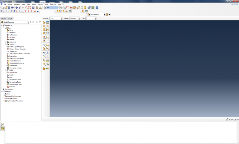
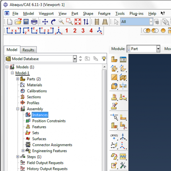
To begin, open a new project in Abaqus CAE. You should see a screen like below:
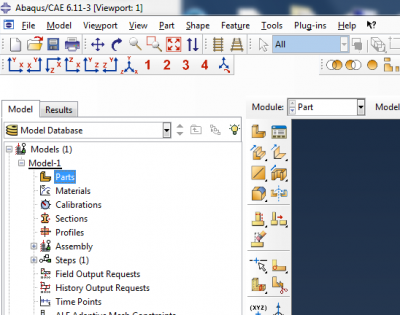
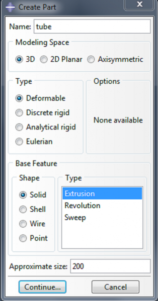
We form the main body of the actuator by creating a tube and then capping it at each end. To make the tube, double click on Parts. Name the part ‘tube’ and make it a 3d deformable solid extrusion.
  |
Now sketch the cross section of the tube. Click on Create Circle: Center and Perimeter.
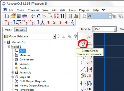
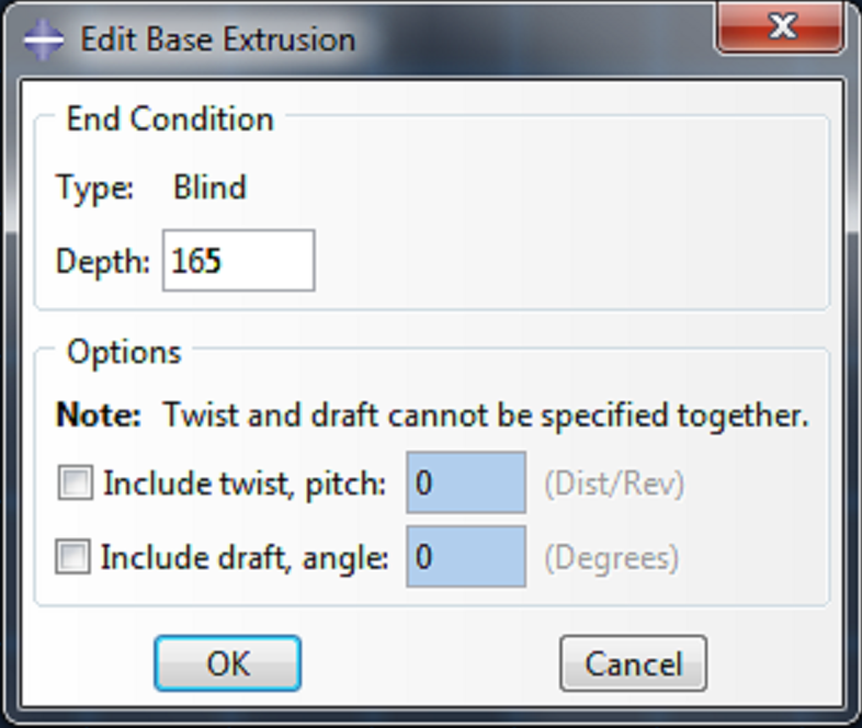 | Enter (0,0) as the center of the circle, and enter (6.35,0) as the perimeter point. Make a second circle with (0,0) as the center of the circle, and (8.35,0) as the perimeter point. Click cancel procedure and done. Enter 165 as the depth, and click OK. |
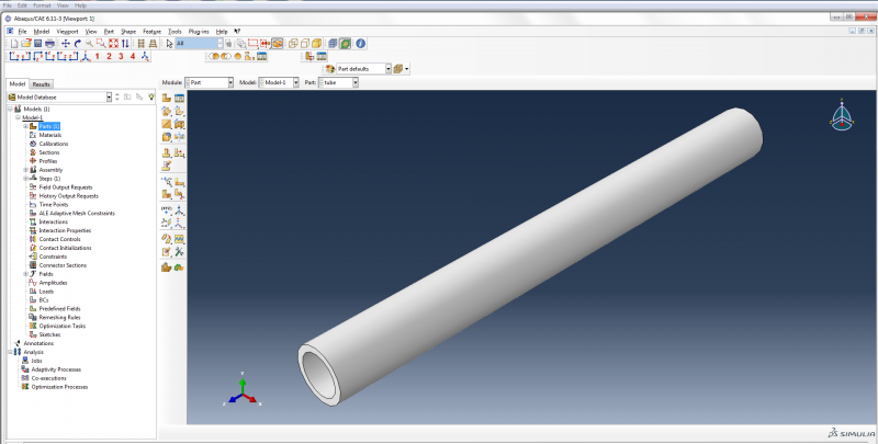
This gives us a tube with inner diameter 6.35mm, outer diameter 8.35mm, and length 165mm.
Create Caps
Next, create the geometry for the caps.
- Double click on Parts again.
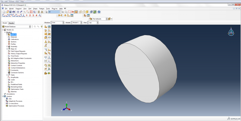
- Name the part ‘cap’ and make it a 3d deformable solid extrusion like the tube.
- Click on Create Circle: Center and Perimeter.
- Enter (0,0) as the center of the circle and (6.35,0) as the perimeter point.
- Click cancel procedure and done.
- Enter 5 as the depth, and click OK.
Add parts to assembly
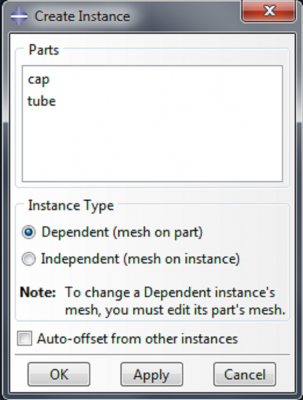
Now we need to merge the tube and the caps to make one part. To do this, we first need to add instances of each part to the assembly. Expand the assembly tree and double click on Instances.
 |
|
| Both of the caps are now positioned at the same end of the actuator, so we need to translate one of them to position it at the other end. In the main toolbar, click on Instance->Translate. |
Click on Instances in the bottom right corner of the screen.
Select ‘cap-2’ and click OK in the instance selection box.
![]()
Enter (0,0,0) as the start point for the translation vector and hit enter. Enter (0,0,160) as the end point, hit enter and then click OK to confirm the position of the instance.
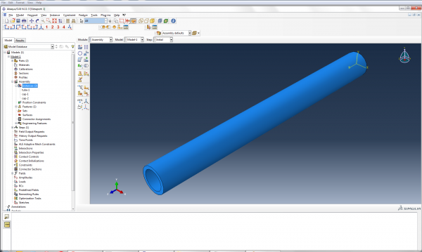
Now there is a cap positioned at each end of the actuator.
Merge parts
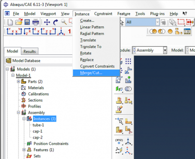
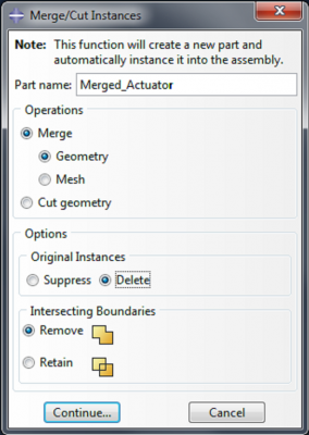
To merge the caps and the tube, go to Instance->Merge/Cut.
Name the new part ‘Merged_Actuator’, select Original Instances: Delete, and click Continue.
When prompted to choose which instances to merge, click on Instances in the bottom right corner. Hold the ctrl key, select the three instances and click OK.
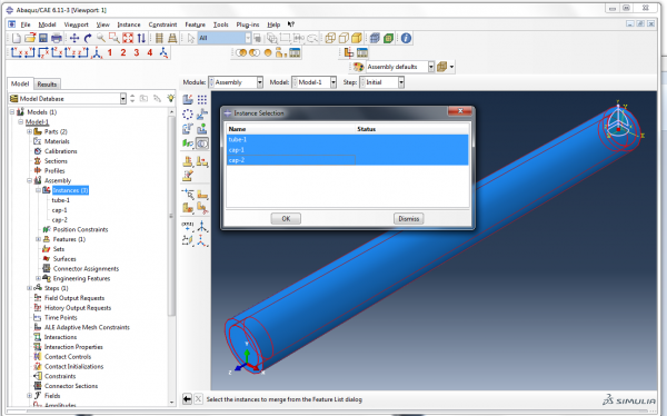
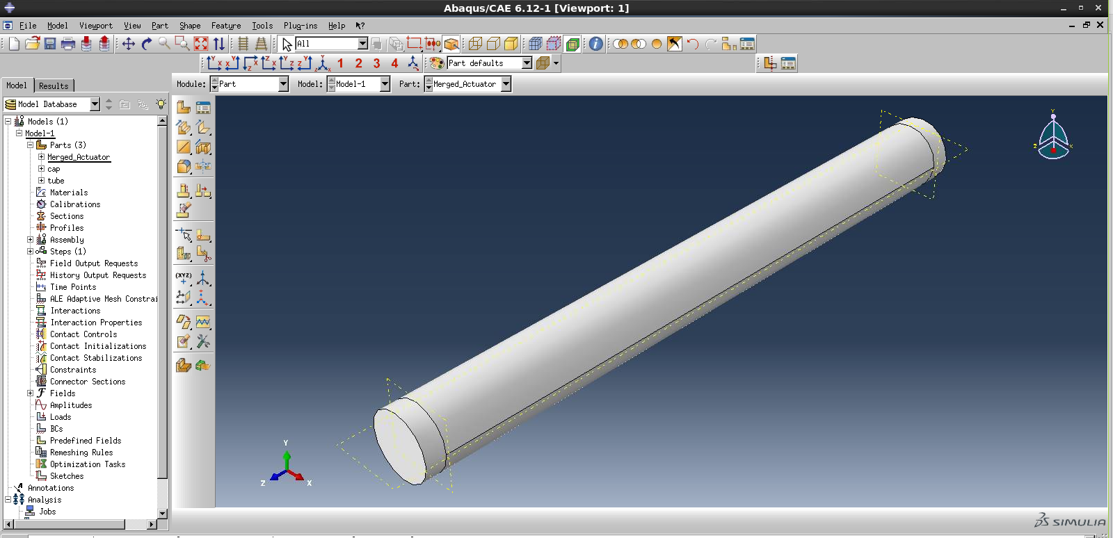
Now we have created a new part called ‘Merged_Actuator’, and an instance of this part has been added to the assembly.
For a bending actuator, we need to partition the actuator so we can assign different materials to the top half and bottom half of the actuator.
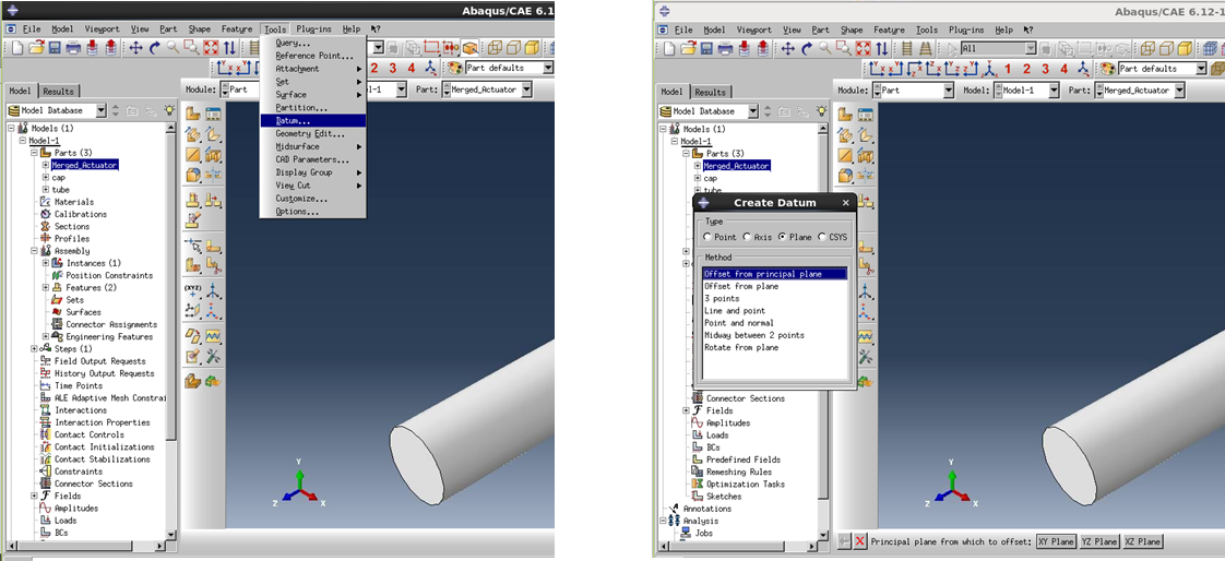
Double click on 'Merged_Actuator' under ‘Parts’ in the model tree. This will allow you to edit the part.
In the main toolbar, go to Tools->Datum. Select Plane, Offset from principal plane. Choose the X-Y plane, and enter 5 (the cap thickness) as the offset amount. Repeat, choosing 160 as the offset amount.
Now go to Tools->Partition. Select Cell and Use datum plane. Click on the first datum plane you created, and click Create partition, to complete the partition definition.
Now click on the main body of the actuator (the cell to be partitioned), click ‘Done’, select the second plane you created and click Create Partition.
Now the caps have been partitioned from the rest of the actuator.
To partition the actuator into its top and bottom halves, define another datum plane: go to Tools->Datum. Select Plane, Offset from principal plane. Choose the X-Z plane, and enter 0 as the offset amount.
Again, go to Tools->Partition. Select Cell and Use datum plane. Select the middle portion of the actuator as the cell to be partitioned, and select the datum plane you just created, and click Create partition, to complete the partition definition.
Now we can assign different materials to the top, bottom and caps of the actuator.