
Create surface for applying pressure
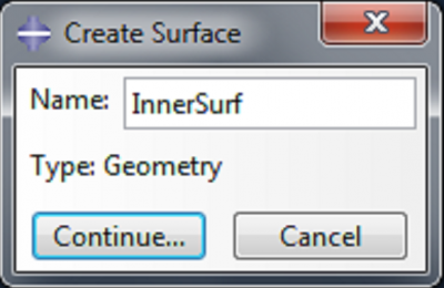
We will want to apply a pressure load to the internal surface of the actuator, so we first need to create this surface. Expand Merged_Actuator under Parts, and double click on Surfaces. Name the surface ‘InnerSurf’.
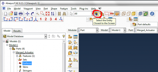
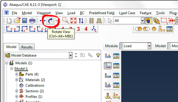
In order to access the inner surfaces, we need to deselect the Select Entity Closest to Screen icon.
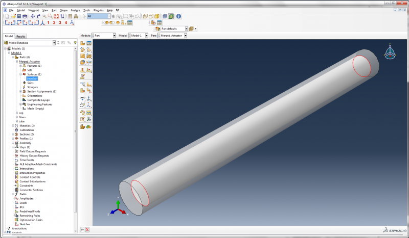
Now hold the shift key and select the inner surfaces of the actuator (the curved surfaces and the two flat surfaces) and click Done. To check that the new surface has been defined correctly, you can go to Surfaces and click once on ‘InnerSurf’, and check that the correct surfaces are highlighted.
Later, we will also need to refer to the outer surface of the actuator, so under Parts->Merged_Actuator, double click on Surfaces again. Reselect Select Entity Closest to Screen. Name the surface ‘OuterSurf’. Select the outer curved surface of the actuator and click Done.
Create Step
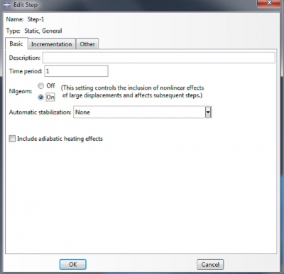
In the model tree, double click on Steps, to create the step in which we will apply the pressure load. Accept the default options of a static general step.
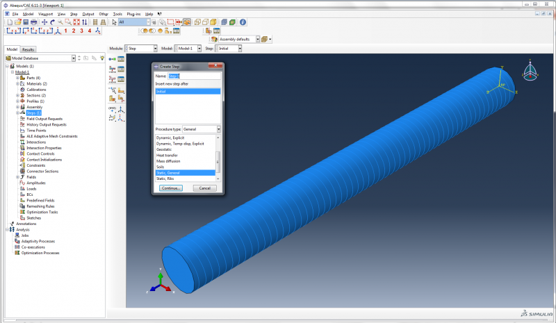
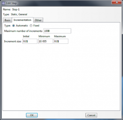
In the ‘Edit Step’ dialog box, select Nlgeom ‘On’ under the Basic tab. Under the Incrementation tab, set 1000 as the Maximum number of increments, 0.01 as the Initial increment size, 1E-5 as the Minimum increment size, and 0.01 as the Maximum increment size. Click OK.
 |
 |
Define Boundary Conditions
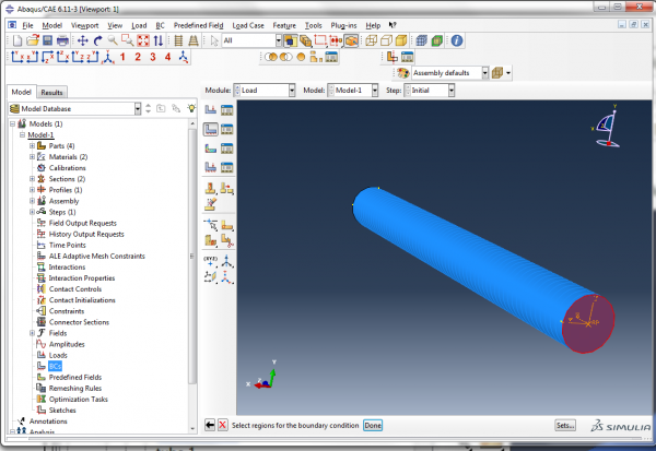
For our boundary condition, we will fix the actuator completely at one end. Double click on BCs in the model tree. Choose Displacement/Rotation as the type of boundary condition and click Continue.
 |
|
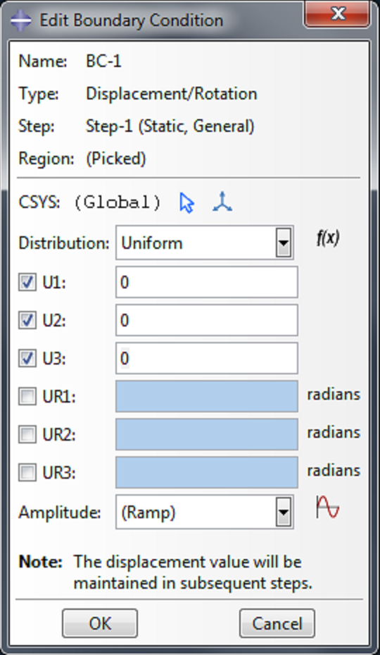 |
We want to impose zero displacement on this actuator face, so check the boxes next to U1, U2 and U3, and accept the default displacement values of 0.0. |
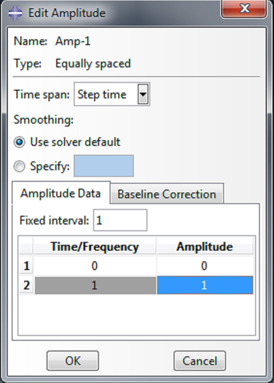
To control the rate at which the pressure load is applied, we create an amplitude. Double click on Amplitudes, and select ‘Equally spaced’. In the ‘Edit Amplitude’ dialog box, enter [0,1] in the coumn under ‘Amplitude’. This will apply the load linearly as a function of time.
 |
 |
Apply load
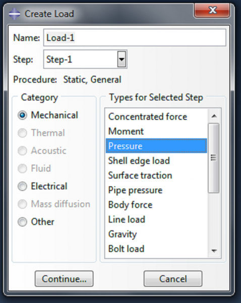 |
Now we define the pressure load, by double clicking on Loads. Select ‘Pressure’ as the load type, and click Continue. |
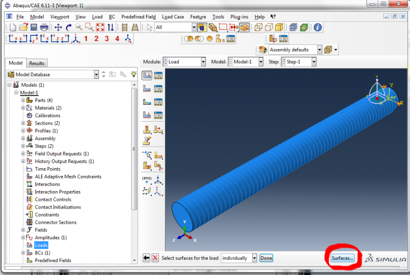
When prompted to select a surface for the load, click on the Surfaces button at the bottom right of the screen.
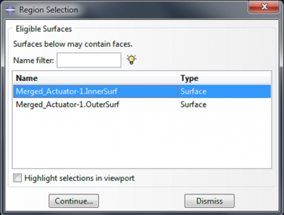 |
Select ‘Merged_Actuator-1.InnerSurf’. |
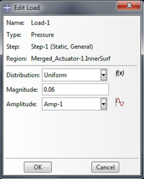 |
Enter 0.06 as the magnitude in the ‘Edit Load’ dialog box, and select ‘Amp-1’ as the amplitude. |