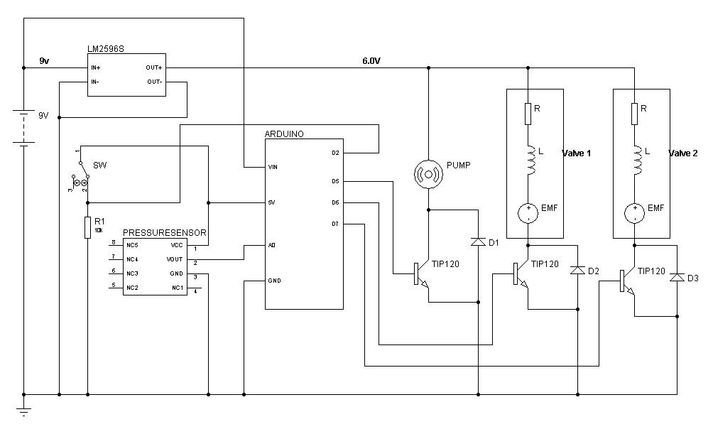
The schematic circuit arrangement for the actuation is shown below

The functions of each of the circuit component are explained below:
Arduino: The Arduino microcontroller is the brain of the regulator system. Here, control commands are written to inflate/deflate the robot, read the system pressure from the pressure sensor to be used as an appropriate feedback.
Transistors: TIP120 which is an NPN Darlington transistors is required to interface the high current external devices to the microcontroller. The pump and solenoid valves make use of high current and cannot be directly connected to the digital I/O pins of the microcontroller. One transistor is required for each of the two the solenoid valves and air pump to drive them at their appropriate current while ensuring that they are controlled by the MCU. When the output pin of the MCU to which the valve/pump is connected to is high (5V), the transistor is active and current is able to flow into the base turning on the TIP120 transistor. When the output pin is low (0V), the collector current, IC, will be zero therefore the transistor is off. In general, the transistor is used to switch current on and off to the solenoid valves and pump; through the transistor, a small current supplied by the microcontroller will switch on a large current that drives the valves and pump. A 1Kohms resistor can be placed between the microcontroller output and the base. This resistor controls the maximum current that can flow from collector to emitter. The circuit is designed to make sure that large currents needed by the dc pump and valves are not supplied by the microcontroller but by the external circuitry. Furthermore, the current should flow from the 6V source, across the pump/valves, through the TIP120 from collector to emitter, and back to the source (without flowing through the microcontroller).
Diodes: The 1N4001 diodes are used as flyback diodes for the valves and pump. Three diodes are required for the pump and valves. When the pump or valve is subjected to a large change in current, such as when the transistor switches, the inductor in the pump and valves presents a large back-emf (back-electromotive force or voltage). This large voltage spike could be harmful, so flyback diodes were required to dissipate this spike. For the air pump, the diode can be soldered across its terminals instead.
Switching Voltage Regulator: The switching voltage regulator is needed to produce a 6V DC output from the 12V power supply in order to power up the valves and pump at the appropriate voltage. The LM2596 DC-DC Switching Adjustable Step Down Voltage Regulator Buck Converter is used to achieve this. It is more efficient to use a switching voltage regulator compared to using a linear voltage regulator because a current of about 800mA is required for the pumps and valves when the circuit is in operation which results in significant amount of heat.
Power supply: The current drawn by the pump is about 150mA and the current drawn by the each of the valves are about 180mA each. Therefore, the power supply should be able to supply at least 800mA of current. A NiMH rechargeable battery can be used or any power supply with at least 800mA of output current and 8V-12V DC output.
