
Initial Design Considerations
To begin the design process, the size of robot had to be decided. Matching the true scale of the adult oceanic manta ray was not an attainable goal since they generally achieve a 240in wingspan. Therefore, a small scale version with a wingspan of 66in was agreed upon. Using anatomical ratios shown in Figure 3.1.1, a body length of 33in was calculated. These dimensions led to a rigid body structure that is approximately 19in wide.
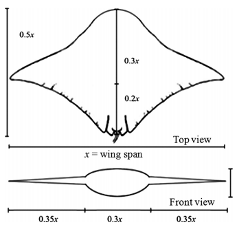
Anatomical Ratios
The central “body” provided several necessary features for the robot. The first was acting as a watertight housing for the batteries, electronics, pumps, and valves that were be necessary for the robot’s operation. The body is also a rigid structure that acts as the ground for the flapping mechanisms. The structure was initially designed in two pieces made up of a bottom tub and a detachable cover with a waterproof seal between the sections. This configuration would allow for easy access for internal assembly, maintenance, and battery exchange/charging. Initial considerations for building the chassis structure consisted of rapid prototyping, milling metal, or injection molding plastic.
The initial design included the fins directly attached to each side of the rigid chassis structure. There were many options that needed to be considered, necessitating the implementation of some small prototypes, before the decision could be made for the hull structure and design of the fins.
Actuation Comparison
Actuation was highly important to the success of the project. Being able to achieve a functional range of motion with a reliable mechanism was paramount in achieving the project’s goals. Desired actuation was based on the nature of the movement of actual manta rays. Achieving a similar magnitude of fin deflection, about 35 degrees, would provide the closest representation of the manta’s motion. Additionally, the design of the sub-systems depended on the method of actuation. Considerations for several types of actuation are explained in more detail below.
Electroactive Polymer Actuation
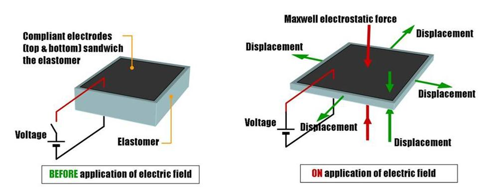
Electroactive Polymer
Artificial muscles refers to use of an electroactive polymer that contracts when electricity is passed through it. One benefit to this method is that the actuation and assembly are one unit. This means the artificial muscle will reach the length of the fin as well as provide the mechanical force to move the fin. This combination results in fewer parts required for the system to function. However, this technology is still relatively new and is prohibitively expensive. Furthermore, other biomimetic projects have cited the electroactive polymers as having a limited range of motion compared to other actuation systems.
Conventional Hydraulic Actuation
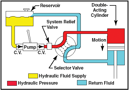
Fluid Actuation System
Fluid driven systems are often used in soft robotics. These systems involve pressurization of a cylinder to move a piston, which applies a force. These systems are generally very reliable and offer uniform loading. Additionally, pumps required for a fluid driven system can be selected for energy efficiency without sacrificing much function in the actuation system. However, due to limited space for the piston to move based on the cylinder’s length, a fluidic system would have significantly limited range of motion.
Geometry Driven Actuation
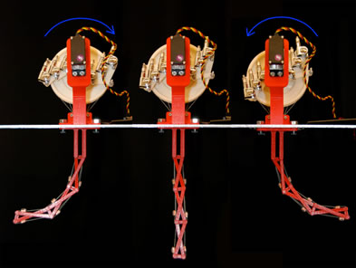
Geometry Driven Actuation
Geometry driven systems use linkages and geometric structures to transfer loads. This allows for wide range of motion and complex motion depending on the configuration of the system. Although these systems are versatile, they can become very complex, making design and fabrication difficult. Additionally, many large geometry driven systems require multiple motors per assembly, making the energy cost relatively high.
Wire Driven Actuation
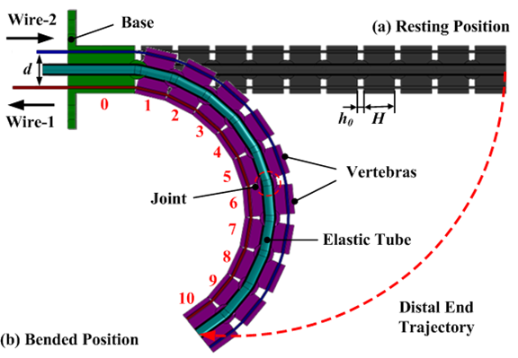
Wire Driven Actuation Cross Section
Wire driven systems use inextensible cables to transfer force along the length of an assembly. These can be paired to offer directional control of the contraction on either side of an assembly, mimicking muscles. Due to space limitations, wire driven systems in submersibles have very limited motion, generally yielding basic two dimensional motion.
PneuNet Actuation
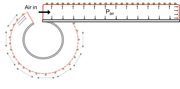
PneuNet Actuation with Restricted Motion
A pneumatic network (PneuNet) actuation system combines the concepts of geometry actuation and fluid driven actuation, allowing the pressurization of tubes or channels to work with geometric structures, yielding a hybrid method of actuation. This system allows a wide range of complex motion due to the ability of the geometric system to bend in multiple directions, and the ability of the fluid system to create equalized pressure throughout the actuation tubes. Fluid systems also use less energy than a mechanical system would, due to the reduced number of actuation devices needed per assembly.
Preliminary Testing
In the decision matrix below, several actuation methods were scored according to whether they hindered, did not meet, met, or exceeded relevant criteria. Based on the results of that decision matrix, two types of actuation were tested for possible implementation. The first was a fiber-reinforced elastomeric tube, derived from the work done by Bishop-Mosher et al. This method was able to produce complex motions including bending and torsion, however, it was difficult to fabricate. The second method involved molding channels directly into the silicone fins. Rows of channels were molded along the top and a row along the bottom of the fin. The flapping motion was created by pressurizing either the top or bottom row of channels.
| Weight | Artificial Muscles | Fluid Driven System | Geometry Driven System | Wire Driven System | Combination of Fluid and Geometry Driven System | |||||
Capable of Complex Motion | 2 | 1 | 1 | 1 | 0 | 2 | |||||
Range of Motion | 2 | 0 | 1 | 1 | 0 | 2 | |||||
Energy Efficient | 2 | 2 | 1 | 1 | 0 | 1 | |||||
Reliable (low failure rate) | 1.5 | 2 | 1 | 2 | 1 | 1 | |||||
Cost Effective | 1 | -1 | 1 | 1 | 2 | 1 | |||||
Low Risk of Leaking | 1 | 2 | 1 | 2 | 2 | 1 | |||||
Proven Results | 1 | 0 | 1 | 2 | 1 | 2 | |||||
Unweighted Totals | 6 | 7 | 10 | 6 | 10 | ||||||
Weighted Totals | 10 | 10.5 | 14 | 6.5 | 15.5 | ||||||
Key: -1 - hinders criteria; 0 - does not meet criteria; 1 - meets criteria; 2 - exceeds criteria
Propulsion System Decision Matrix
Combinations of Fluid and Geometry Driven Systems
Fiber Reinforced Elastomeric Tube System
Fiber reinforced elastomeric tube actuation relies on the interaction between the expansion of the tube and the rigidity of the fiber surrounding it. As the tube expands horizontally, the fibers limit the movement of the tube in certain directions based on how it is configured. With proper design, exact motion can be achieved with this system. Combining multiple tubes yields a larger range of complex motion. Multiple systems of these tubes in a sequence would theoretically have allowed for the motion desired for a manta ray fin.
Multi-Elastomer Actuation System
To implement fiber-reinforced elastomeric tubes, they would have needed to be pre-fabricated. The silicone fins would then be poured around the tubes. This guarantees the tubes to be perfectly fitted inside the fin, allowing all generated forces to be applied directly to the fin.
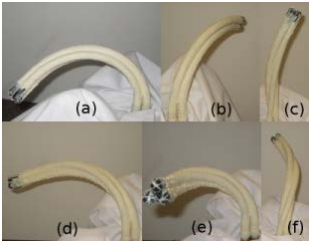
Several of these actuators were fabricated using latex tubes wrapped with different configurations of sewing thread that were bonded using rubber cement. These tubes were difficult and time consuming to construct because the threads needed to be placed precisely. The prototypes were tested by pressurizing the tube with air from a bike pump. It was found that the prototypes had very limited and erratic motion. In addition, there were problems effectively sealing the free end of the tubes. Ultimately, the complexity in the fiber placement, the length of the process and low output deflection made it impractical to move forward with this design.
Silicone Pneumatic Network Bending System
After the failures with the fiber reinforced elastomeric tube actuators, some more research was done for the pneumatic network bending system. One excellent resource was the Soft Robotics Toolkit, a well-respected Harvard research website. This included many small scale example actuators that used the pneumatic network method, including step-by-step instructions for manufacturing them. The WPI Soft Robotic Fish paper was another useful resource that implemented this type of molded silicone actuator to create a successful biomimetic robot that mirrored the flexibility and movement of a fish. Due to the similarities in application to the manta ray, this became the chosen type of actuator to move forward with in prototyping.
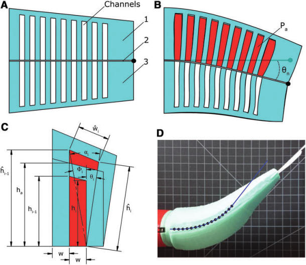
Soft Robotic Fish Actuation
Small Scale Fin Prototypes
There were several iterations of small scale fin prototypes consisting of different designs and materials to determine which combination would be the best option for scaled prototyping and, ultimately, full sized fins. Some simple simulations were conducted in SolidWorks to try to predict the response. Later, these simulations were compared to the results of the small prototype tests to verify the validity of the models. Although initial simulations proved promising, more complex models resulted in large discrepancies between projections and actual results.
Full Fin - Oomoo
The first set of prototypes was modeled as a small scale full fin cast in silicone. Oomoo was the silicone chosen for the properties of 240 psi tensile strength and 250% elongation at break. The mold was created as a two part model in SolidWorks then 3D printed. The size of the mold allowed for a fin that was approximately ¼ scale of the final design choice.
The full fin mold had an open top to allow polystyrene foam channel inserts to be suspended in the mold and for the uncured silicone to be poured. The foam was carved by hand into two half cylinders and then wrapped in string to create strategic inextensibility as shown by the Fiber Reinforced Actuators in the Soft Robotics Toolkit. The string wrapped around the outside of the foam was to prevent the channel from expanding outward in all directions, constraining deformations to the axial direction. Another set of strings lying against the flat face of the half cylinder in the root-to-tip direction created the inextensible layer across the chord line of the fin that would cause it to curl rather than stretch linearly. For this to actually be implemented, the foam channels were set in the silicone then melted out with acetone. The strings on the outside of the foam stayed embedded in the silicone to provide the structure for the movement once the channels were filled with fluid. The two channels for the small scale fin were placed on either side of a laterally oriented center plane to allow movement in both directions depending on which channel was filled.
Two Channel Full Fin Mold and Oomoo Positive
To test it, a manual bike pump was attached to the inlet hole of one channel and pressurized air was pumped in. This prototype fin failed to actuate because the channels did not provide sufficient area for the length and thickness of the silicone.
Another small full fin was cast with the same foam and string concept, but one large channel was created with the intent of decreasing the amount of silicone that needed to be actuated. The channel followed the same shape as the fin, keeping a consistent edge size. The inextensible string was along one side, which meant the fin would theoretically only bend in one direction when filled air.
There was a minimal amount of actuation when this was tested because the silicone proved to be too thick. Cutting down the edges improved deflection slightly, but after some more testing the strings began to fall out of the silicone. They were unable to be completely embedded in the silicone during the curing because of the way it was laid against the foam. This method was determined to be unreliable and inexact in implementation, so other methods were pursued.
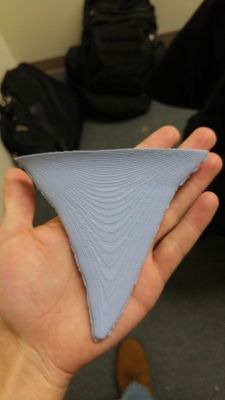
Half Fin - Oomoo
The next method used to create the fin drew inspiration from the manufacturing techniques used for the WPI Soft Robotic Fish. Instead of making one mold for one fin, the fin would be constructed of two symmetrical halves with an inextensible layer between them. Rather than embedding polystyrene or other materials for the channels fully in the silicone, the mold for half the fin utilized a panel that molded the channels directly into the silicone. This allowed for more precisely made channels and consistent models.
The new printed mold was slightly larger than the first, but maintained the shape and proportions of the first small scale fin, which had been modeled extensively in SolidWorks. The set of channels was designed with one main channel running from the fin root toward the tip of the fin. Four perpendicular channels were spaced equally across approximately one third of the fin. This way the outer two thirds of the fin remained passive, allowing for more natural motion. Additionally, this passive tip was intended to create beneficial vortices, providing greater thrust. The channels were half cylinder shaped with a constant radius. The widths of the channels across the fin varied in an attempt to keep the distances to the leading and trailing edges the same.
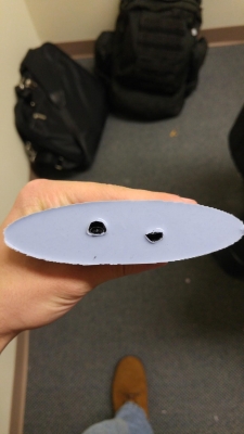
An inextensible layer was created separately by laying a section of tulle mesh on a flat surface and pouring silicone over it. The mesh allowed the inextensible layer to bend and twist, but not stretch in any direction. Once the silicone half fin was set, the two parts were bonded together with more silicone. A small opening to the main channel allowed the connection to the bike pump.
The first test was promising, however, very quickly the bond around the channels started to fail. This resulted in essentially one large channel, but there was still some actuation in one direction which indicated that the inextensible layer was functioning properly. Attempts to cut open the fin and fix the bond around the channels with high strength adhesive failed, but did prove that super glue does not adhere well to silicone.
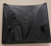
Half Fin - Dragon Skin
Once the Oomoo had been used up, the decision was made to switch to Dragon Skin 10 for its increased compressibility, flexibility and elasticity. Dragon Skin 10 has a tensile strength of 475 psi, over twice that of Oomoo, and 1000% elongation at break. The same half mold was cast once more with the new silicone. Using the old inextensible layer did not work because Oomoo does not bond to Dragon Skin. A new inextensible layer was created the same way as before, but with the Dragon Skin, and the two parts were bonded together.
Dragon Skin Upper Fin Section
During the bonding process, some of the channels filled in with the extra silicone, but there was still significant performance improvement using the Dragon Skin over the Oomoo. The material properties of the Dragon Skin allowed for more deflection from the fin root to tip. Because of the increased compressibility and elasticity, the fin was able to bend much more easily. Once again, after repeated testing the bonding between the channel walls and the inextensible layer started to weaken and eventually failed, separating the layers
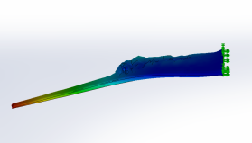
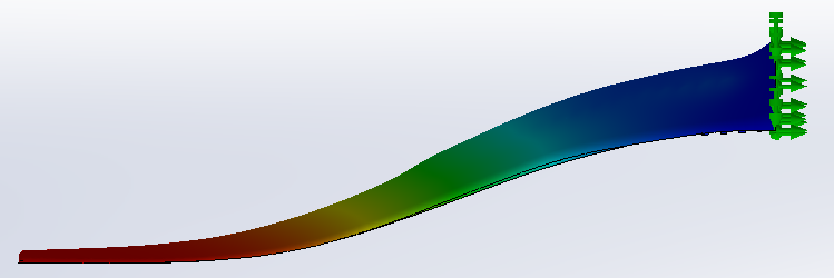
Comparison of SolidWorks Simulation with Actual Results
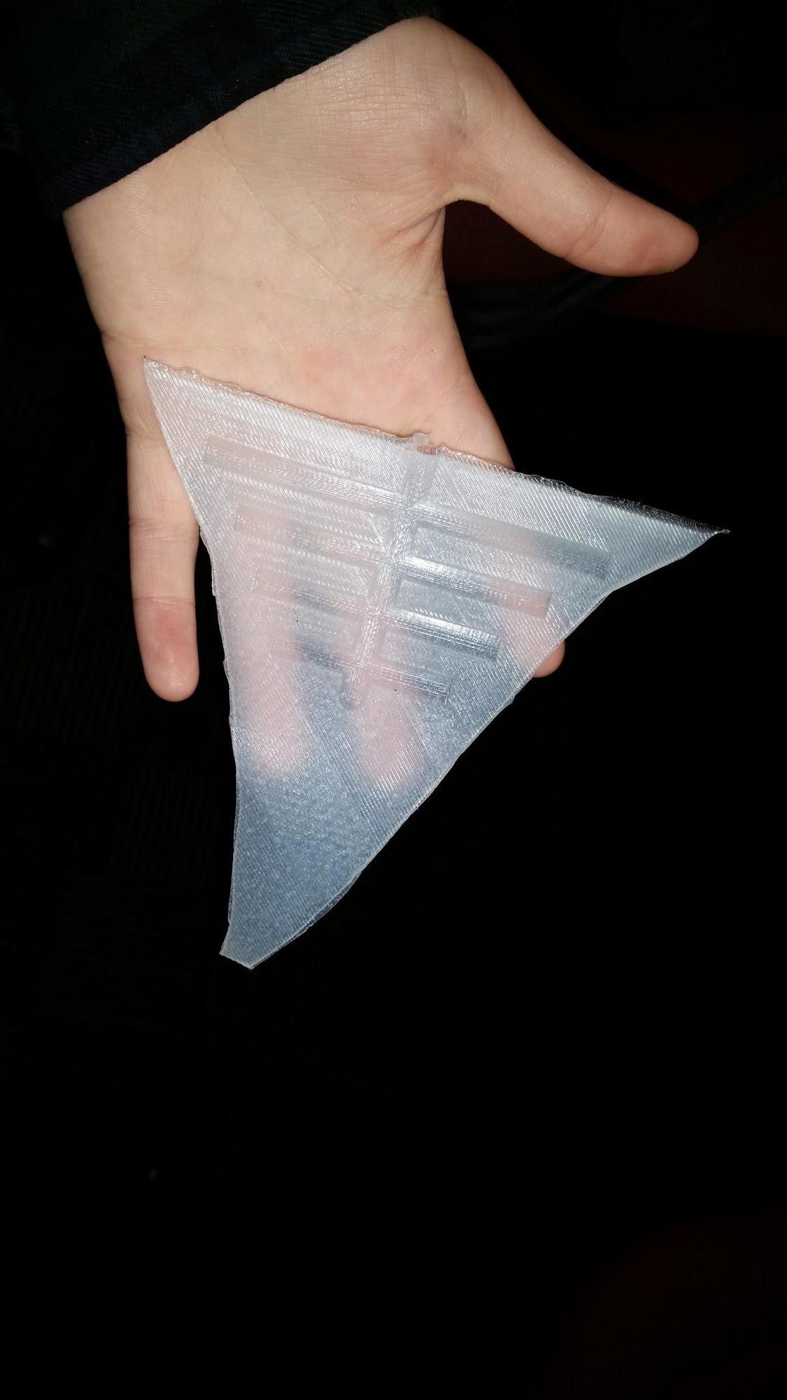
Dragon Skin Half-Fin Iteration 1
A new design was simulated in SolidWorks for the channel configuration of the same fin. A simple static simulation was conducted. The data sheet for the DragonSkin did not include all of the material properties required, so certain aspects needed to be derived. To complete a full half wing and allow it to actuate, a very thin layer was added to close the channels. This layer had the material properties of Delrin acetal plastic, which is flexible but inelastic. The thick end of the fin was fixed and a pressure of 50 psi was added uniformly to the inner surfaces of the channels and areas of the inextensible layer that were covering the channels.
The semi-cylindrical channels were replaced with rectangular channels of varying depths such that their distances from the top of the fin were each the same. They were also much thinner and closer together. The simulations showed that this allowed more actuation with less bulging because the forces were more equally distributed and there was less material per channel to deform.
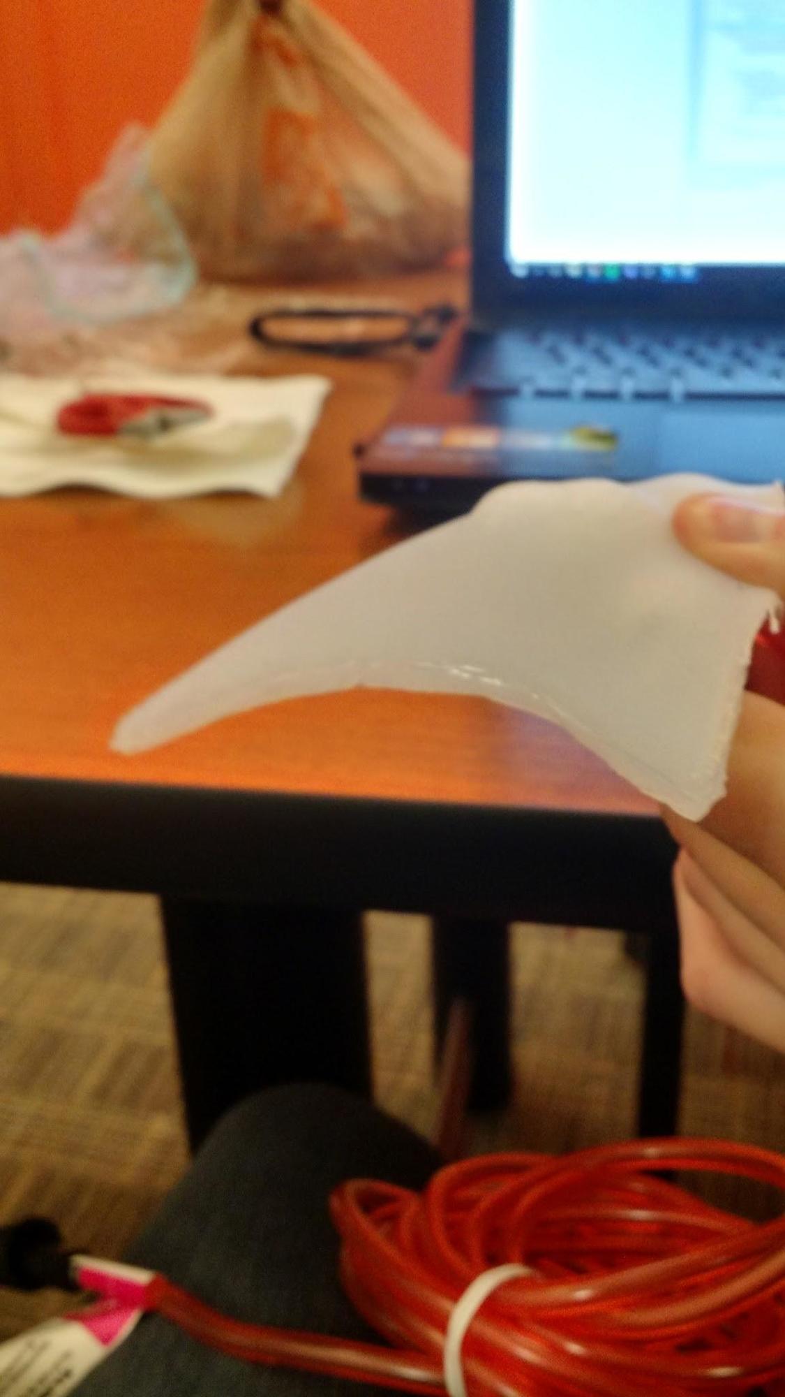
To try to avoid issues with the bonding failing between the fin and the inextensible layer, the silicone was poured onto the mesh and the fin was placed immediately on top of it. The intention was that the new silicone would bond well to the fin rather than depending on a very small amount of silicone to bond two separate pieces. With this method, channel loss was significantly reduced; only the last, smallest channel filled in.
This prototype was the most successful of the small scale tests with almost 90 degrees of actuation. There were a few places where the fin expanded perpendicular to the desired direction, with bulges where the material was thinner, which shows the consistency needs to be increased in future prototypes. With this improvement, this design was chosen for the final design.
While the 90 degrees of actuation was promising for the project, this was a result that deviated a significant from the SolidWorks simulation. This was most likely due to a more complex model than the previous fin and over-simplistic choice of simulation. In addition, the derived material properties for the DragonSkin represent a potential source for error. The confluence of factors likely resulted in the inaccurate simulation. Given the unreliability, the decision was made to discontinue simulating the models.
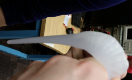
Comparison of SolidWorks Simulation with Actual Results
Dragon Skin Half-Fin Iteration 2
Fin Manufacturing Process
Due to limitations on rapid prototype molding, namely the build area of available 3D printers (approximately 10in x 6in with the Makerbot 2), it was not an appropriate production method for larger fins. Therefore, in order to create an 18in fin, a new production method had to be devised. In order to save on materials costs for testing iterations, before going directly to full scale from the small scale, it was decided to develop production methods with a medium scale fin.
In order to make a negative mold of an object, a positive is required. A small test was done with the high density foam, previously used to create channels, to see how difficult it would be to carve a fin positive. Two pieces of foam were glued together to create a cube. From this point, using knives and rasps, a rough 6in foam fin was shaped by hand.
Once the positive was created, plaster was mixed as the mold material. Plaster is inexpensive, cures quickly and is a common material for making reusable molds. As proof of concept, the foam fin was suspended in a paper cup and the plaster was poured around it. Once set, the plaster block was cut in half to remove the fin.
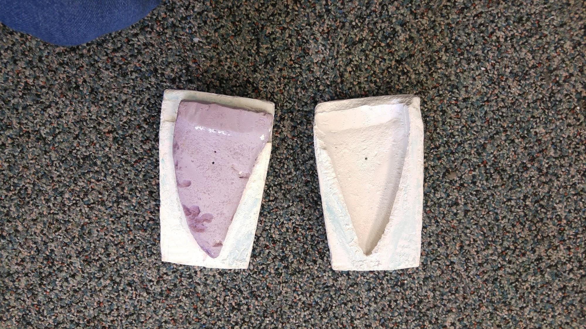
Small Scale Plaster Test
This process demonstrated that plaster could be used for a mold for a larger scale design. There were, however, a few things that needed to be improved. For instance, cutting the mold introduced potential for failure, as the plaster was prone to crumbling. To avoid cutting, the decision was made that the molds would be created for one half of the fin at a time, similar to the methodology employed for the small scale mold. Another place for improvement was the interface between the foam and the plaster. The foam was slightly pitted and porous, creating an imperfect mold.
With this new knowledge, it was decided the medium scale fin would be more feasible as the final prototype. This was based on the manufacturing time expected with each fin pour, and the cost of volume of silicone needed for the project.