
The initial testing of the soft robot was tethered and used a breadboard. This allowed for any changes to be made to the circuit before switching to PCB. Although a breadboard could have been used inside the untethered robot, the PCB offered a much cleaner alternative that also saved space which proved to be valuable in layout of the internal components.
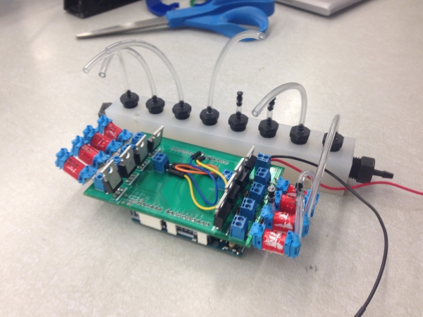
Printed Circuit Board with manifold
One of the goals of this project was to create a soft robot that was untethered, containing all components inside the robot. In order to do this, the team designed a printed circuit board (PCB) with all necessary elements soldered on. The purpose of having the robot untethered was to allow more freedom and maneuverability. By printing a custom control board, they were able to reduce the size of the circuit which made it possible to house everything on the robot. The PCB was also attached to an Arduino Uno microcontroller which performed all necessary commands to make the robot roll.
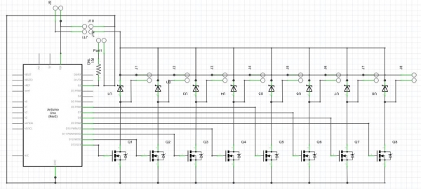
Schematic of the circuit that was printed on the control board.
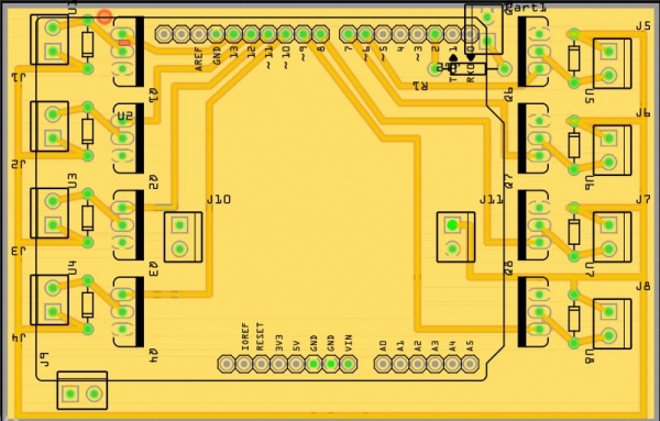
PCB layout
The circuit designed for the robot was used to actuate the different channels in the mold. Elements on the circuit diagram include N-type MOSFETs, Zener diodes, resistors, and screw terminals to connect solenoid valves. The circuit itself is designed to receive a signal from the Arduino microcontroller that will open and close each valve at different times. The team used MOSFETs in order to improve the response time between each valve and the microcontroller. Zener diodes were used to prevent high voltage spikes in the MOSFETs, reducing the risk of frying a transistor.
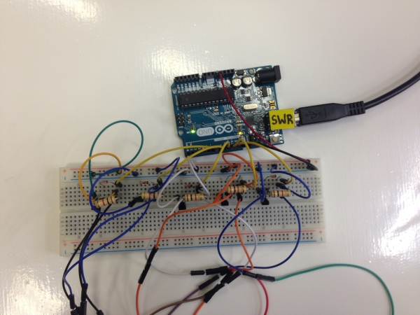
Initial testing was done using a breadboard.
The distribution of weight of components housed inside the cylinder was important to the motion of the robot. The team needed a center of mass that was as close to the center of the robot as possible because the robot’s inertia would cause a non-uniform roll. To keep all the internal components intact, they laser cut acrylic rings each with cutouts that would support all necessary elements.
With the first set of acrylic rings, all components were positioned without any adjustability. The team quickly realized that the regulator and CO2 cartridge were by far the heaviest of the internal components. With the positioning of the original rings, the center of mass of the cylinder was drastically off-center. As can be seen in the video below, the inflating channels on the robot were not able to overcome the extra mass. It could roll through most areas, but would get stuck at the point where the heavy components sat at the bottom of the cylinder.
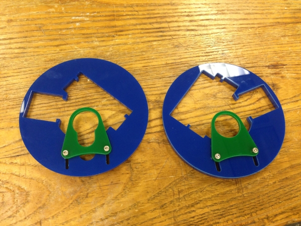
Rings with slider to adjust location of regulator and CO2 cartridge to balance robot.
To accommodate the regulator and CO2 cartridge, the team designed rings with the cutout for the regulator and cartridges on a slider which could be moved closer or further away from the center of the cylinder. This feature allowed for testing those components at different positions, and finding the location along the slider where the robot was best balanced.
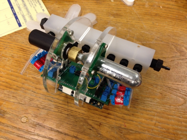
Acrylic rings holding the internal components
The internal components of the soft robot include one Arduino Uno microcontroller, one printed control board, an 8-valve manifold, a regulator, a 16 gram air cartridge, a 9V battery, 1 switch, 4 acrylic rings to support everything, and several tubes to inflate the soft robot. The air cartridge served as the robot’s air supply. The size of the cartridge was small enough to fit inside the robot, allowing for the robot to be untethered. The air cartridge was connected to a regulator, which helped maintain a certain pressure in the robot and kept the air cartridge from exhausting quickly. The air cartridge/regulator combination was the heaviest part inside the robot. In order to adjust for the weight, the team laser cut the acrylic rings to hold a slider that attached to the cartridge/regulator. This made for an easy solution to adjusting the center of mass of the robot. The regulator connected to the 8-valve manifold, with each valve connected to the PCB. This allowed for equal pressure to be distributed in each channel of the robot. The manifold was the largest component of the robot; therefore it was important that other components such as the PCB be located opposite of the manifold. The microcontroller and PCB controlled the timing of when each valve opened and closed, allowing for proper inflation and deflation time in each channel. The 9V battery and switch were made accessible by attaching them to an acrylic ring at the edge of the robot.-
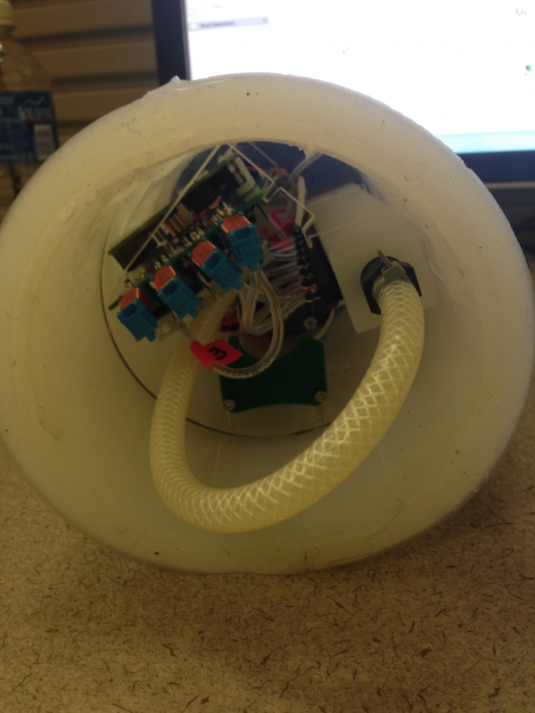
Soft Robot with all internal components inside