
PCB
The printed circuit board was designed to accommodate 8 solenoid valves, with each controlled via a zener diode and MOSFET connected to the Arduino Uno's digital pins. Screw terminals were used to connect the leads from the valves to the PCB. The files to print the board are attached, and the components were soldered on according that schematic. Heat sinks were used when soldering the MOSFETs to reduce the risk of frying them.
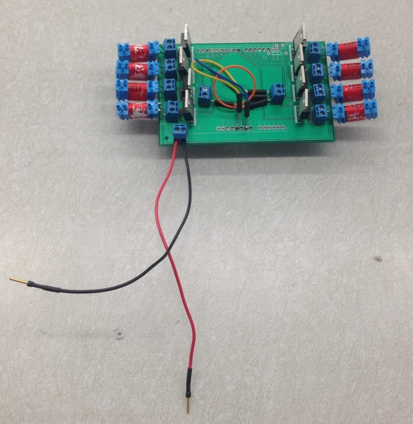
PCB with components soldered on.
Code
The code to control the actuation sequence of the solenoid valves is very simple. Each valve is assigned a digital pin number, and then by setting that pin high, the valve opens the port from the manifold to the silicone channel. By setting the pin low, the connection from the silicone channel to the exhaust port is opened. A variable is set for the time to leave a pin high to inflate it, which we found to work best at 250 msec. Another variable is set for the time to allow the channels to deflate, which we set to 500 msec. The driving channels are called in a for loop so that they actuate in sequence around the perimeter of the cylinder.
Files
| PCB Layout Files for Printing | 211 KB | |
| Arduino Code Text | 1 KB |