
|
The PneuNet actuator documented here consists of a series of chambers arranged in a row, where the thinnest wall sections are those between each chamber and the next. The strain-limiting layer is a piece of paper embedded in the base. When the device is inflated, the chambers expand, and the thin walls between the chambers bulge out the most. This would cause the actuator to expand in the axial direction, but since the strain-limiting layer does not expand, the actuator bends instead. |
|
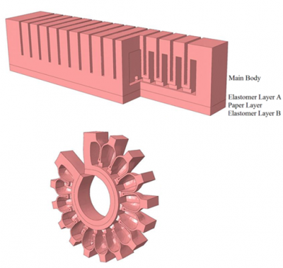
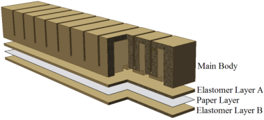
| The actuator consists of two parts: the main body, which expands when inflated, and a base containing the inextensible paper layer embedded in elastomer. |
|
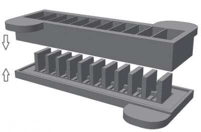
| To build this actuator, the main body and the base are cast separately and then glued together. The base of the actuator is a simple rectangular plate. The more complex main body is cast in the two-part mold shown here. |
|
The behavior of the actuator is determined by the materials from which it is made and the shape of the chambers. The next two sections provide some guidelines for selecting materials and designing the shape (or "morphology") of the actuator.
The following section contains a detailed tutorial on making solid models of the actuator and molds using SolidWorks. The resulting SolidWorks files can be downloaded here, and the .stl files for 3-D printing the molds can be downloaded here.
