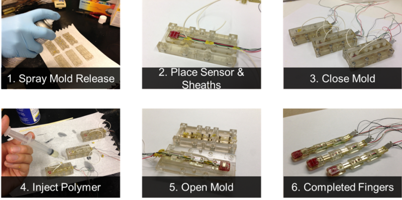
For fingers with more complex cross-sections that cannot be achieved with open-top molding, we can 3-D print two-part, closed-top molds. A complication of the closed-mold approach is the inability to machine the pocket for the flexible joint material. As such, a separate molding process must be performed to mold the flexible joints independently. This section does not provide a definitive guide to mold design; however it does present a case study and describes factors of the closed molding process that must be taken into consideration.
Considerations for closed-top molding
The fabrication process for closed-top molds is slightly different from that for open-top molds:
1. Mold Release: Apply liberally. This is very important. Unlike wax, 3D-printed resin cannot be broken and easily separated from the molded finger. Also spray on the clamping surface so any elastomer leakage doesn’t lock the mold shut once cured.
2. Component Placement: Your molds should contain features to align any components you want to embed in the finger.
3. Closing the Mold: Clamp tightly with socket-head cap screws.
4. Degassing: In contrast to the open-top mold, it is best to degas the elastomer before injecting into the mold. Limited exposure to the air makes it difficult for bubbles to escape once the fluid is injected into the mold, creating voids in the finished part.
5. Filling: As the mold is closed, you will likely need to use a syringe to inject fluid into the segment cavity. This must be done very carefully and slowly so you don’t introduce bubbles into the mold. If possible, use a translucent material as your mold material so you can visually inspect the quality of the injection. Depending on the viscosity of the fluid, gravity might not be enough to adequately fill tight spaces within the cavity. A good technique is to design inflow and outflow sprues into the mold, wherein the fluid is injected into the segment cavity at one location, and allowed to eject from the cavity at another location. This allows the fluid to circulate and leverages the pressure differential to fill the cavity.
Closed-top mold design
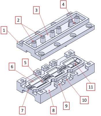
The following image shows the features of a closed mold used to fabricate a 3-jointed SDM finger with an embedded pressure sensor.
|
|
|
Closed-top molding steps
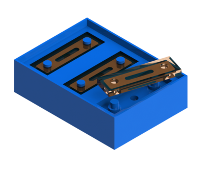
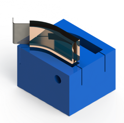
Step 1: Mold the individual flexural components first. This can be done using an open-top molding process.
  |
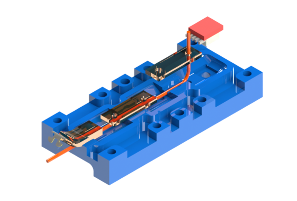 |
Step 2: Place the various flexural components, as well as the cable sheath and any sensors/wiring, into the master mold. |
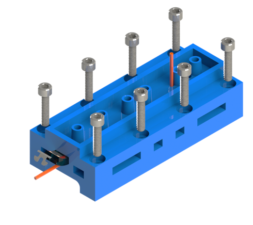 |
Step 3: Close the master mold and tighten securely with screws. |
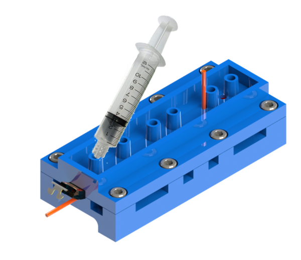 |
Step 4: Carefully introduce high-modulus elastomer into each compartment using a syringe. |
