3D printing soft gripper stiffened by passive particle jamming
Introduction
A variety different kinds of soft actuators based on different working principles have been developed. Most soft grippers do not allow stiffness modulation when grasping, these actuators cannot provide very high stiffness and large grasp force, thus the weight that such a soft gripper can hold is limited.
Researchers have proposed some ways to increase the stiffness of a soft gripper. For stiffness modulation of soft grippers, current methods need dedicated design and control, complicating both the actuator geometric configuration and the control process. Fabrication of multi-functional soft grippers is time-consuming and its processes are complex.
The proposed 3D printing soft robotic gripper is stiffened by passive particle jamming, shown as in Fig. 1. We aim to design a soft gripper that can achieve higher stiffness as well as simplify the design process. The objectives and significance of the proposed gripper are:
- To stiffen a pneumatic soft actuator in object grasping without the need of any control process.
- To increase the stiffness variation band so that both soft and hard objects could be grasped.
- To 3D print the soft actuator without the need of additional assembly processes.
This research is a revision and upgrade according to a published paper: Li, Y. T., Chen, Y. H., Yang, Y., & Wei, Y. (2017). Passive Particle Jamming and Its Stiffening of Soft Robotic Grippers. IEEE Transactions on Robotics.
 |
Mechanism of Proposed Finger
Related Literature Review on particle jamming
Soft grippers based on particle jamming have exhibited some promising properties in variable stiffness and shape conformity.
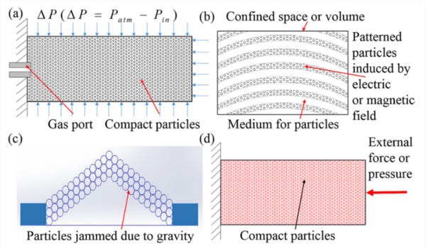
The soft gripper reported by Eric Brown, et al. utilized the mechanism of vacuum particle jamming whose fundamental working principle is shown in Fig. 1 (a). A bag of particle is forced to conform to an object shape, and the vacuum is turned on to jam the particles so that the stiffness of the gripper can be significantly increased. In the vacuum jamming condition, the pressure difference between outer atmosphere pressure and the inner air pressure results in a continuous and evenly distributed pressure jam the granular materials inside. By controlling the vacuum pressure, the gripper’s stiffness can be increased and changed instantly.
This gripper is suitable for grabbing objects with irregular shapes, but it cannot be deformed or bent actively and all the geometry changes lie on the target object it is going to grab. Another weakness for this gripper is that it cannot respond to active environment like the general elastomer grippers.
Similar works utilizing the vacuum particle jamming for robotic hand design were also reported by Jiang, et al. Apart from vacuum based particle jamming, there are alternative ways for particle jamming. In rheology based jamming, particles capable of responding to specific inductions are evenly distributed in material medium inside a confined space or volume, such as air, fluid, emulsion, foam or elastomer. By applying external electric or magnetic fields, particles will rearrange following the patterns of induced fields. The interaction force between particles induced by fields will force them to squeeze to each other, thus increasing the stiffness of the confined volume.
An illustrative diagram for this theory is shown in Fig. 2 (b). This method had some applications in robotics such as the ER (electrorheological) robots [4-6] and MR (magnetorheological) robots. All these methods require huge electric or magnetic fields, meaning that they will need many extra auxiliary devices, thus complicating the design of robots. Another possible method in increasing the stiffness of particles is to use gravity as shown in Fig. 2 (c), even though no researchers have ever utilized this method to design robots. Li, et al. observed that particles will jam by exerting an external pressure/force to a compact volume of particles as in Fig. 2 (d).
 |
Mechanism of The Proposed Design (passive particle jamming)
For our design, the mechanism causing the passive jamming is totally different from above-mentioned vacuum jamming or rheology jamming. Instead of jamming under inner and outer pressure difference or external fields inductions, the particles will squeeze to each other and rearrange in a more compact form under an externally applied load.
The working mechanism is illustrated in Fig. 3. When the actuator is under original state, the particles are loosely arranged in the soft sheath. As soon as the pressured gas are given into the actuator, particles in the soft sheath will be squeezed due to the expansion of the actuator. Main pressure comes from the interface of the jammed chamber and the air chamber. These squeezed particles are proven to be able to provide certain stiffness as they are jammed in certain space. This mechanism of particle jamming is promising for stiffness modulation in pneumatic soft actuator design. This is the key principle we utilized in this work.
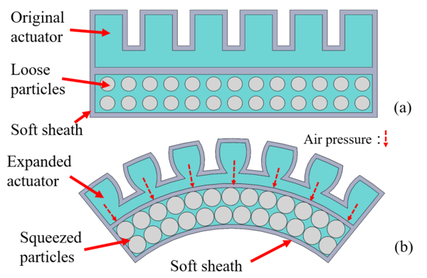 |
| Fig. 3. Passive particle jamming mechanism: (a) Original state. (b) Particles jammed due to expansion of the soft actuator. |
Design
3D Model Design
The proposed finger is pneumatic actuated. The 3D model of the proposed finger is shown in the Fig. 4. It can be seen that the finger is designed into two parts, the air channels and the jamming chamber. The air channels are designed in a way that the actuator will mainly bend around two joints. The jamming chamber will be filled with particles after fabrication. It should be noted that there is a cuboid support designed for the air inlet as there will be no support when 3d printing. And for the jamming chamber, a small notch with width about 1mm is designed for filling in the particles. This notch will be sealed with hot glue gun afterwards. Basic designing parameters are shown in the Fig. 5. There are some key parameters that makers should pay attention: thickness of the air channels are 1.6mm, and the diameter of the air inlet is 3.2mm (4mm air tube can be directly insert).
 |
 |
Fabrication
The soft actuators were fabricated using NinjaFlex® flexible 3D printing filament, which was produced by NinjaTek and fabricated by a 3D printer Makerbot Replicator 2X. Properties of the NinjaFlex® is listed in Table 1. This material can be bought from the website: https://ninjatek.com/products/filaments/ninjaflex/.
With reference to work by Yap, et al, the 3D printing process parameters are set as in Table 2. The diameter of the extruder we used is 0.4mm, and that’s the reason for designing the wall thickness to be 1.6mm as we want 4 layers of material are printed to ensure the air-tightness of air chambers.
H. K. Yap, H. Y. Ng, and C.-H. Yeow, "High-Force Soft Printable Pneumatics for Soft Robotic Applications," Soft Robotics, vol. 3, pp. 144-158, 2016.
| Properties | Materials |
| Density/g∙cm-3 | 1.19 |
| Tensile strength (Yield) /MPa | 4 |
| Tensile modulus /MPa | 12 |
| Hardness | Shore 85A |
Table 2 Main parameters of the 3D printing process
|
Parameters |
Values |
|
Extruder temperature for NinjaFlex filament (℃) |
245 |
|
Extruder temperature for Conductive filament (℃) |
220 |
|
Build platform temperature (℃) |
40 |
|
Nozzle size (mm) |
0.4 |
|
Layer thickness (mm) |
0.1 |
|
Shell thickness (mm) |
1.6 |
|
Print speed (mm/s) |
30 |
|
Print infill |
100% |
Fig. 6 shows the 3d printing direction of the finger. It should be noted that although the air chamber and jamming chamber are hollow, no support structures are required for 3d printing process as the elastic material itself can keep the upper surface from collapsing. 3d printing process of the finger is shown in Fig. 7. After the finger is printed, particles will be pouring into the jamming part. The particles that we used to fill in the finger is plastic balls with diameter 4mm. And as shown in Fig. 8a, there is a small notch designed for pouring in the particles. The entire process is shown as Fig. 8. After the finger is full of plastic balls, the notch will be sealed.
 |
 |
 |
Testing
Definition of Rotational stiffness
The stiffness of the gripper is defined as rotational stiffness, whose definition formula is expressed as:
\(S = M/\theta=Fl_{F}/\theta\) (1)
where \(S\) is the gripper’s rotational stiffness, \(M\) is an applied moment and \(\theta\) is the gripper’s rotation angle. In (1), \(M\) is expressed as an applied force \(F\) parallel to the \(Y\) axis times its length of force’s arm. To simplify calculation, we make a reasonable assumption that under a small displacement at the gripper’s endpoint, \(l_F\) remains the same value. The definition of stiffness and the associated parameters are shown in Fig. 9.
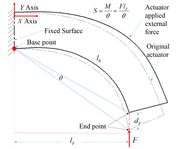 |
| Fig. 9. Definition of rotational stiffness and its associated parameters. |
Experiment Study
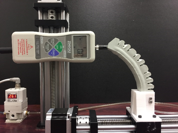
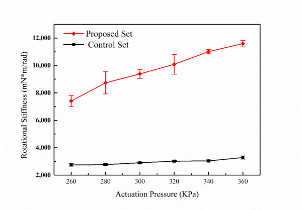
To measure the gripper’s rotational stiffness, a two axis measurement platform (controlled by stepper motors) is designed and assembled as in Fig. 10. At different air pressure, the gripper is moved forward 5mm and the force gauge value is read. At each actuation pressure, the test is repeated 10 times and the results are plotted in Fig. 11. The vertical bars represent the standard deviation. The red line shows the results of the proposed actuator while the black line shows the same actuator without passive particle jamming. It can be seen from the overall trend that the rotational stiffness value of the proposed actuator is about as much as four times of the gripper without particles.
 |
 |
Case Study
Design of robotic gripper
In this project, we design a three-finger robotic gripper. The three soft actuators (fingers) are assembled into a gripper base as in Fig. 12.
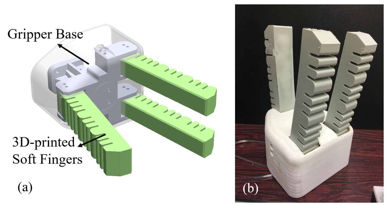 |
| Fig. 12. 3D model and prototype of the proposed robotic hand |
Detailed dimensions of the gripper are presented in Fig. 13. The workspace can be calculated from the opening angle of the fingers (20°): the opening distance is 105mm, and the effective length of the gripper is 128mm. The entire robotic gripper is 211mm (height)* 115mm (width)* 159 mm (length) in dimension.
 |
Grasping demostration
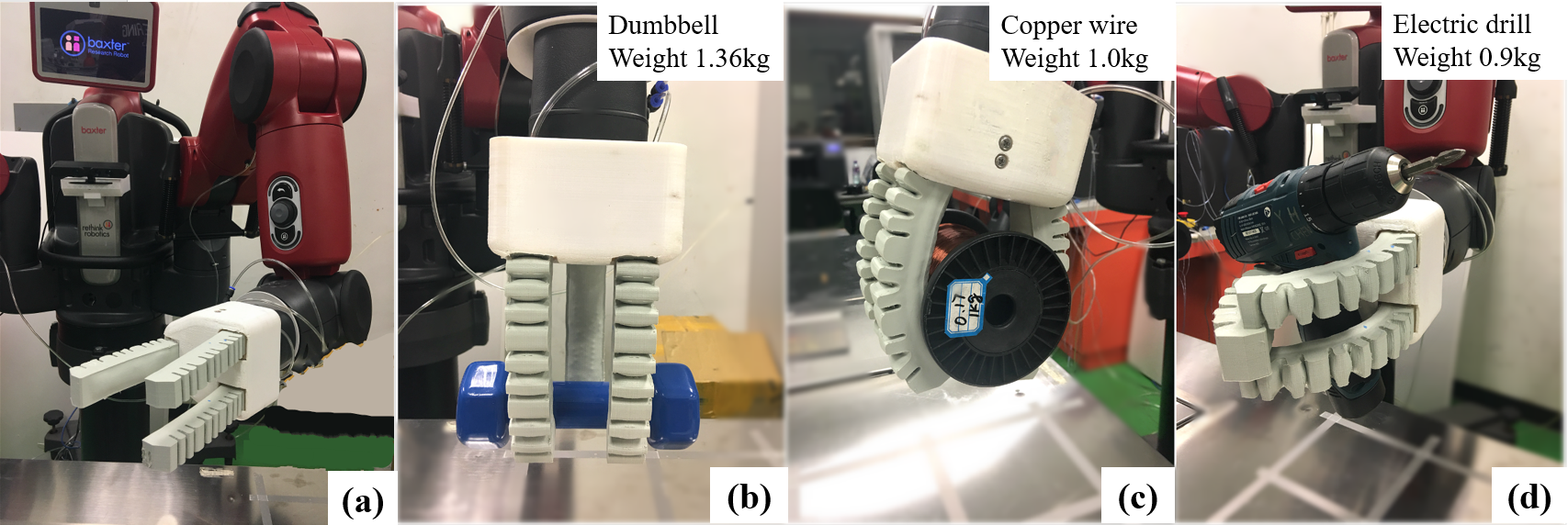
As described in the previous section, the proposed finger design is able to provide appreciable stiffness compared with the normal design. Due to the passive jamming of particles when the soft actuator bends, the gripper has good load bearing ability. We conducted grasping experiments to display the gripper’s grasping capability. The robotic gripper was installed to the left arm of Baxter, as shown in Fig. 14 (a). Three objects were grasped for testing the gripper’s load bearing ability. They are a dumbbell, a roll of copper wire and an electric drill, as illustrated in Fig. 14. The pneumatic pressure for the actuator is about 0.36 MPa (above standard air pressure). A video has been recorded to show more of the grasping tests, and it is submitted together with the proposal.
 |
|
|