Testing
Definition of Rotational stiffness
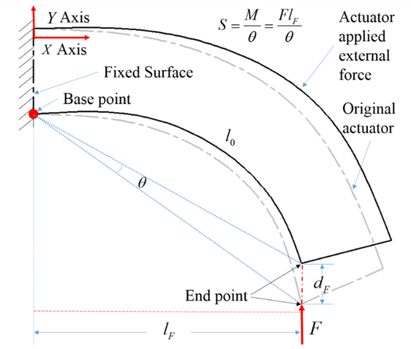
The stiffness of the gripper is defined as rotational stiffness, whose definition formula is expressed as:
\(S = M/\theta=Fl_{F}/\theta\) (1)
where \(S\) is the gripper’s rotational stiffness, \(M\) is an applied moment and \(\theta\) is the gripper’s rotation angle. In (1), \(M\) is expressed as an applied force \(F\) parallel to the \(Y\) axis times its length of force’s arm. To simplify calculation, we make a reasonable assumption that under a small displacement at the gripper’s endpoint, \(l_F\) remains the same value. The definition of stiffness and the associated parameters are shown in Fig. 9.
 |
| Fig. 9. Definition of rotational stiffness and its associated parameters. |
Experiment Study
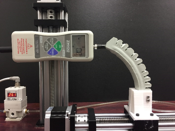
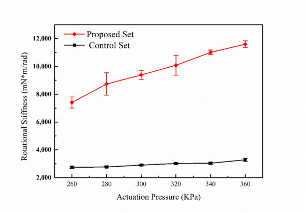
To measure the gripper’s rotational stiffness, a two axis measurement platform (controlled by stepper motors) is designed and assembled as in Fig. 10. At different air pressure, the gripper is moved forward 5mm and the force gauge value is read. At each actuation pressure, the test is repeated 10 times and the results are plotted in Fig. 11. The vertical bars represent the standard deviation. The red line shows the results of the proposed actuator while the black line shows the same actuator without passive particle jamming. It can be seen from the overall trend that the rotational stiffness value of the proposed actuator is about as much as four times of the gripper without particles.
 |
 |