Design of robotic gripper
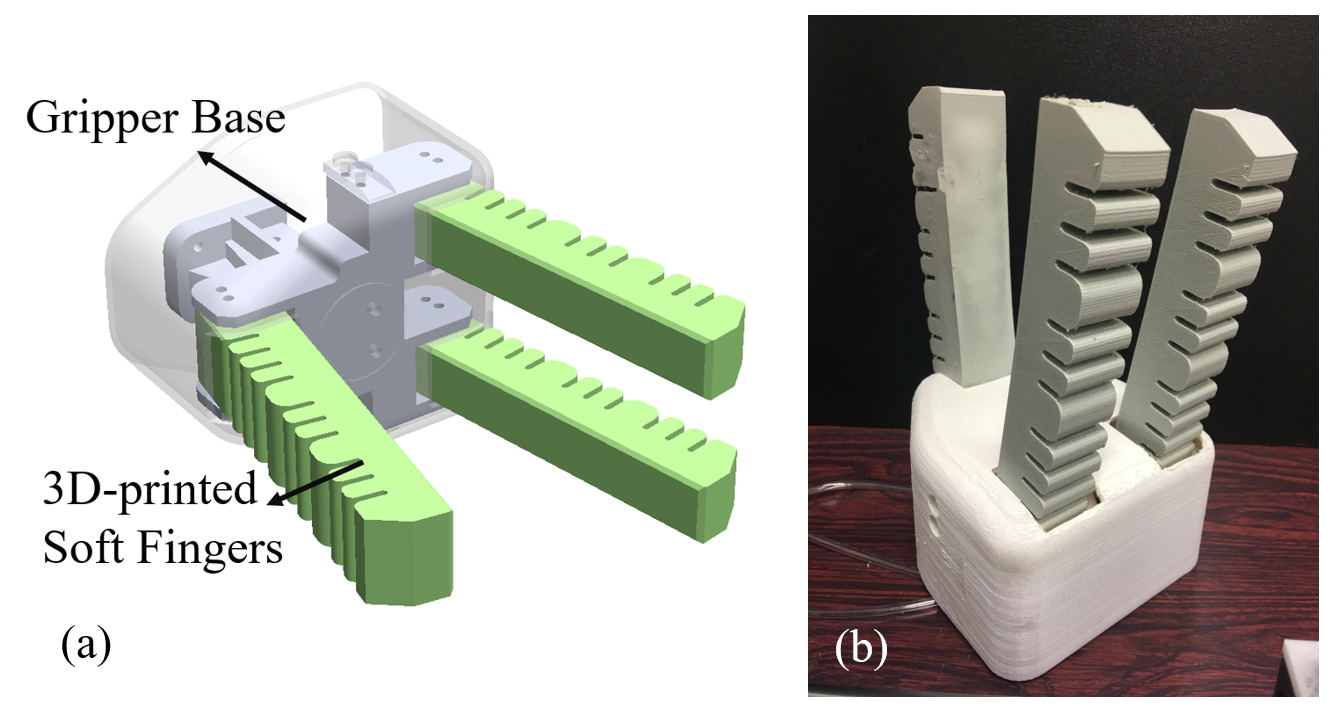
In this project, we design a three-finger robotic gripper. The three soft actuators (fingers) are assembled into a gripper base as in Fig. 12.
|
|
|
Fig. 12. 3D model and prototype of the proposed robotic hand
|
Detailed dimensions of the gripper are presented in Fig. 13. The workspace can be calculated from the opening angle of the fingers (20°): the opening distance is 105mm, and the effective length of the gripper is 128mm. The entire robotic gripper is 211mm (height)* 115mm (width)* 159 mm (length) in dimension.
Grasping demostration
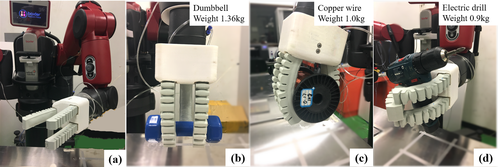
As described in the previous section, the proposed finger design is able to provide appreciable stiffness compared with the normal design. Due to the passive jamming of particles when the soft actuator bends, the gripper has good load bearing ability. We conducted grasping experiments to display the gripper’s grasping capability. The robotic gripper was installed to the left arm of Baxter, as shown in Fig. 14 (a). Three objects were grasped for testing the gripper’s load bearing ability. They are a dumbbell, a roll of copper wire and an electric drill, as illustrated in Fig. 14. The pneumatic pressure for the actuator is about 0.36 MPa (above standard air pressure). A video has been recorded to show more of the grasping tests, and it is submitted together with the proposal.


