Design
Inspiration
Honeycomb structures are masses of regularly arranged hexagonal prismatic wax cells constructed by honey bees in their nests for containing their larvae and storing honey and pollen.
| A honeycomb shaped structure can provide a material with minimal density and relative high out-of-plane compression and shear properties. Engineers have applied the honeycomb structure to numerous engineering and scientific applications. |

|
Inspired by the honeycomb, a novel structure coined 'honeycomb pneumatic network' was esablished as part of this actuator. Honeycomb has the property of high elongation rate and crush resistance, while the pneumatic networks system is lightweight, rapidly responsive and environmentally benign. HPN combines these properties by placing pneumatic units inside the honeycomb-shaped structure.
Design overview
|
The HPN manipulator documented here consists of a honeycomb-shaped frame and a series of pneumatic networks arranged within. The manipulator can be constructed upon several segments with different parameters. Each segment contains four pneumatic network groups, each consisting of 8 chambers connected consecutively. These pictures show an overview of single segment of HPN manipulator and it's deformation in two different directions.
|
|


Honeycomb Structure
Design parameter
For the same material, different structures can make vast difference on mechanical properties.

Specifically, for a single honeycomb chamber, the figure above illustrates the difference of deformation about different wall thickness and with the addition of grooves under the same pressure and cross section area. The structure with a thicker wall appears are more stable however the addition of the inner grooves imparts additional flexibility to the structure.
Thus, we use flexibility and load bearing capacity as the evaluation metrics of mechanical property of the HPN manipulator. Flexibility is defined as the ratio of the reachable area of the manipulator's tip to the square of manipulator's original length. And load bearing capacity is defined as the maximum load moment under the condition that the manipulator's tip can hold stably at the same height with its fixed end. The definitions have relations with the original length of the manipulator, however, the connection can be approximately omitted.
Later, we will illustrate the model design procedure and use FEM simulations to estimate the relationship between flexibility, load bearing capacity and wall thickness, as well as groove depth. The result can be viewed on the testing page.
Honeycomb structure
|
The honeycomb structure we use to make manipulators consists of compressed hexagonal chambers. This structure has many advantages, such as a high elongation rate and crush resistance, When airbags inside pressurize, some of the chambers deform, so the structure elongates or bends.
Before making our model we must determine the design parameters. There are several dimensions that affect the actuator’s behavior: wall thickness, and groove depth.
|
|


Model design CAD tutorial
This tutorial contains step-by-step instructions for making a solid model of a Honeycomb structure in SolidWorks 2015. The SolidWorks part files can be downloaded here. If you prefer to use a different software package, you should be able to apply the general tutorial steps to most solid modeling environments or you can refer to the dimensioned figures below.
In addition, there are other design parameters to be determined: chamber height, and overall number of chambers.
In this tutorial we will make an honeycomb structure with 2 columns, each column have 8 chambers. Each chamber is 3.5 mm long, 39 mm wide, 60 mm high, with 2 mm wall thickness. Of course, you can alter these parameters to change the morphology of your actuator yet general steps covered in the tutorial should still apply.

Design Individual Chamber
There are many ways to make the honeycomb structure, in order to make it easy we will introduce it here step-by-step.
The general overview of steps entails first creating a fragment of one chamber, and complete it using symmetry operations. After that, the whole manipulator can be achieved by replication based on one chamber and patterning to achieve the network.
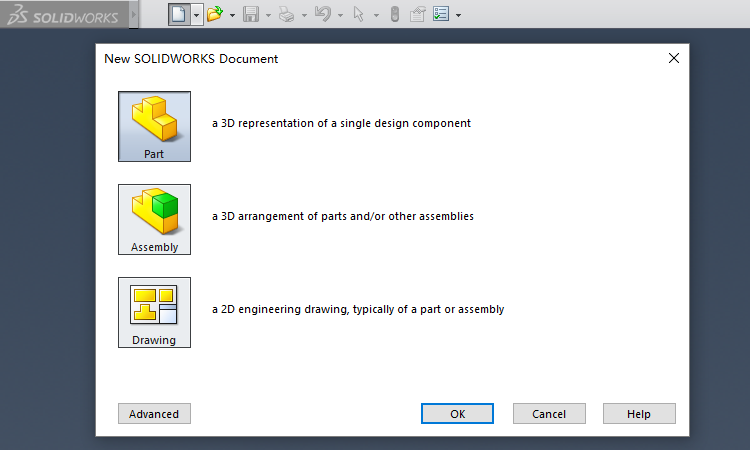
First step, launch Solidworks and create a new Part.
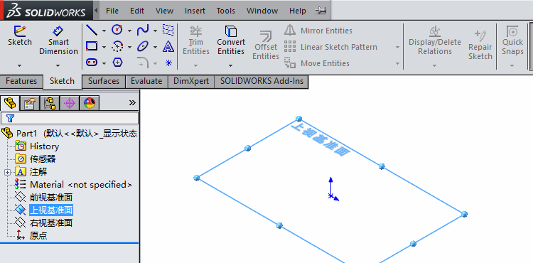
Next, select a datum plane and begin to sketch.
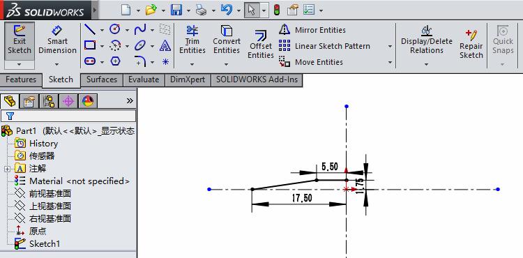
Next, we draw the sketch of a single honeycomb chamber. Because the chamber is a symmetrical hexagon, we only draw its quarter and then mirror it twice (using the Mirror Entities operator).
Now it's the sketch of one quarter of the hexagon shown below.
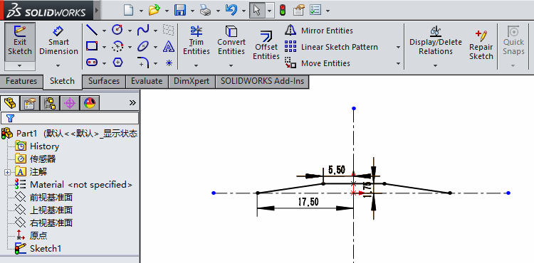
Mirror it for the first time, and we get the upper half of the hexagon.
Mirror again, and we get the whole hexagon.
Then, we use the Offset Entities operator, with the distance of 2 mm, to get the chamber with desired thickness.
Groove on the Corner
As discussed before, there are two parameters affecting the mechanical property of the manipulator: wall thickness and groove depth of the honeycomb structure. In this step, we will implement 2 mm depth grooves in sketch.
Below is the single chamber finished in last step.
We draw a rectangle with a depth of 2 mm and a width of 0.4 mm at the inner acute angle.
Then we obtain grooves on two sides using the Mirror Entities operator.
Pattern Sketch
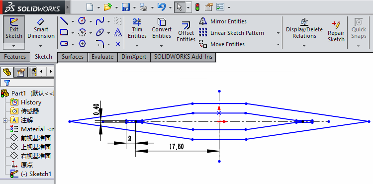
The manipulator frame is composed of two lines, with 8 chambers on each line. In this page, we show how to sketch that using Linear Sketch Pattern and Move Entities operators.
Here is the sketch of a single chamber with inner grooves finished in last step.

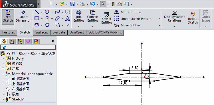
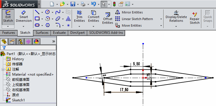
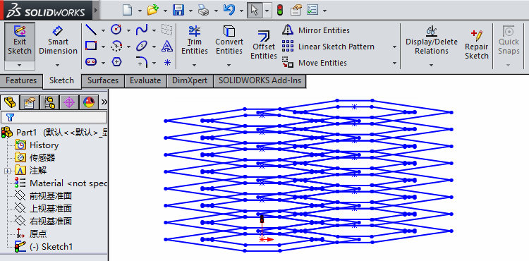
We use Linear Sketch Pattern operator and pattern it as below, with instances as 8 and spacing as 5.5 mm.

Click Accept (green check mark on the left), and finish the pattern. The result is shown below.

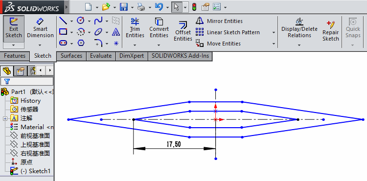
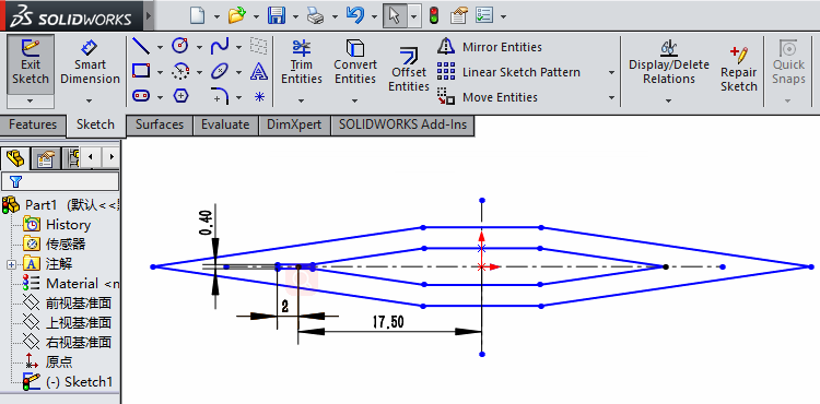
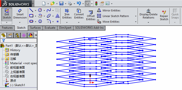
Then, enable Move Entities operator, and select start point and end point at the red points shown below.


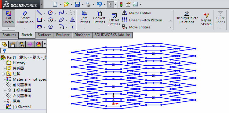
Click Accept, and get the sketch below.

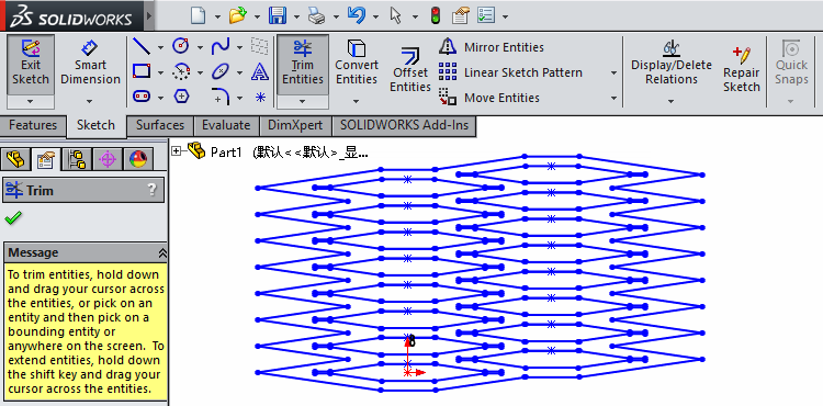
Trim
In this page, we trim the sketch using the Trim Entities operator based on last step. The result will be used for extrusion later.
As shown below, we have drawn the sketch of the whole honeycomb structure.
First, select redundant lines and delete them by clicking delete button on the keyboard. We need mention that the two lines on the upper and lower boundaries cannot be directly handled in this way.
So we use Trim Entities operator to cut the extended area on the two lines at boundary.
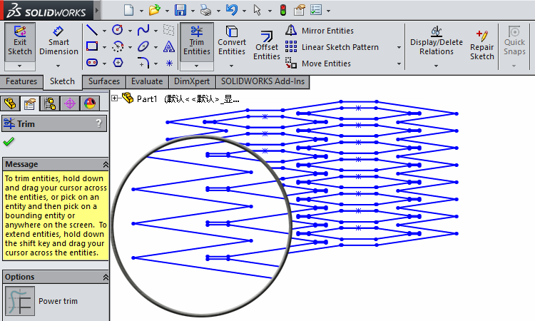
Then, we also use Trim Entities operator in order to cut the redundant lines at the inner grooves, which can be observed in a magnified view.

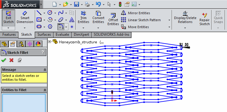
At last, we use Fillet operator and smooth the structure's two edges as seen below.
Extrude
In this page, we illustrate the procedure of obtaining a 3D structure using the Extrude command.
The figure below is the trimmed sketch from last step.
We select Extruded Boss/Base command in 'Features' panel, and select the colored area in the figure below.
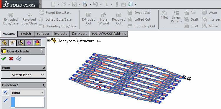
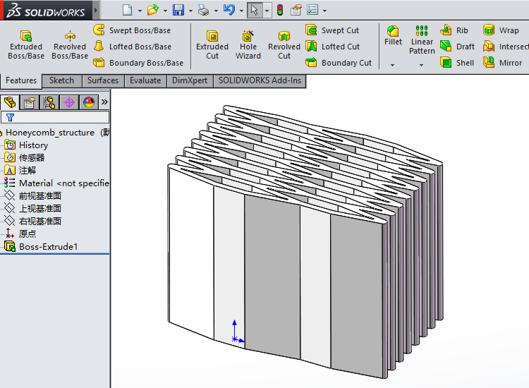
Set the height as 60 mm.
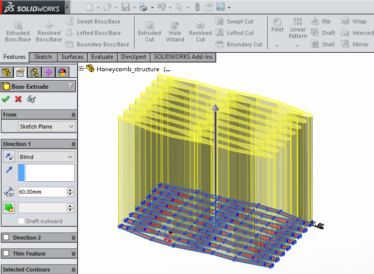
Click Accept (green check mark) and get the final 3D honeycomb structure.
Pneumatic Networks
|
The pneumatic network is an important part of HPN manipulator. In this section, we will introduce an innovative design of this proposed pneumatic network. |

|
|
Conventionally, when we talk about the pneumatic network, the first idea is a series of chambers connected together through specific designed channels (click here to see an example). This is a bottom-up way to build the whole structure from fragments. In the following paragraph, we will introduce the method in which to construct the pneumatic network, which is low cost and durable. The main part of pneumatic network we put here is air columns bag made of PA/PE, which has many advantages listed as follows:
In order to make it easy to assemble the pneumatic network with the honeycomb structure, a column of airbags is divided into 16 individual chambers (as shown in the picture) by heat-sealed tortuous channels. Picture (B) shows the details of measurement and the design of two ends. 16 chambers can be divided into 8 segments, with every two adjacent segments connected through a long tortuous channel with a long air tube inside. Similarly, every two chambers in the same segment can be connected by a shorter tortuous channel with an air tube inside. For the air inlet, we use a straight connector to make it easy to inflate the pneumatic network. When assembling this pneumatic network with honeycomb structure, we can fold the pneumatic network from every short tortuous and plug it into every single chamber of honeycomb structure. The resulting AutoCAD files can be downloaded here. |
|
|


