Fabrication
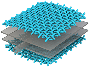
This section contains detailed step-by-step instructions for making a HPN manipulator. As explained in previous sections, the HPN manipulator consists of two parts: the main body consisting of 5 segments of honeycomb structure which were designed with different parameters, and pneumatic networks containing a mass of air chambers arranged regularly. The two parts are fabricated separately and then assembled together.
Process overview

|
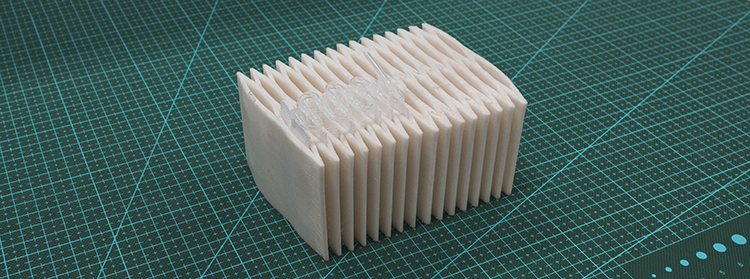
The fabrication method of the honeycomb structure was accomplised with the technology of 3D-printing, however, limited by the work space of 3D printer, the honeycomb structure of HPN manipulator was divided into 2 parts, each part was printed individually. The material we used to print is PolyFlex which is a kind of TPU that has good features of highly flexibility and a large strain-to-failure, is easy to be print by almost all desktop FDM/FFF printers. |

|
Pneumatic networks are fabricated manually. With the help of bag sealer machine, we can put Air Column Bag into pneumatic network. |

|
When finished with the fabrication of honeycomb structure and pneumatic networks, we can assemble them together easily. This is a single segment of HPN manipulator which consist of one segment of honeycomb structure and 4 pneumatic networks. When inflated with different pressure, the manipulator can deform in different directions as well as enlongate. |
Honeycomb Structure
As we discussed before, the whole manipulator consists five parts, in order to achieve a balance between flexibility and load bearing capacity, the frame of each part was designed with different parameters. This is a tutorial about the fabrication of a single segment.
Honeycomb structure was build with the technology of 3D-printing, The STL file for 3D-printing can be download here.
3D printer
MakerBot Replicator 2X Experimental 3D Printer
Cilck here to buy.

Material
PolyFlex (1.75 mm; 750g) White
Click here to buy.

Honeycomb structure

limited by the workspace of the 3D Printer, we divide the honeycomb structure into two sections and printed them independently. After that, we connected the two parts with clips. Here is an video shows the process.
|
|
Pneumatic Networks
This section contains detailed step-by-step instructions for making a pneumatic networks manually.
|
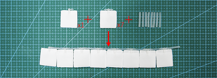
As explained in the design of pneumatic network section, the pneumatic network consists of 8 segments. The two adjacent segments are connected by a long silicone tube that is round. Further more, each segment has two airbag chambers which are connected by a short silicone tube. |

|
Process overview

|
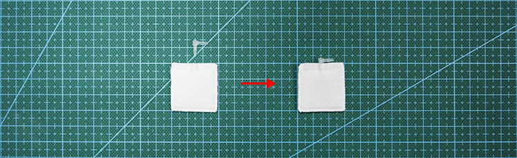
Prepare air bags The main body of pneumatic network is Air Column Bags whose material is PA/PE. The first setp to fabricate pneumatic network is cut a single column of air bag off.
|

|
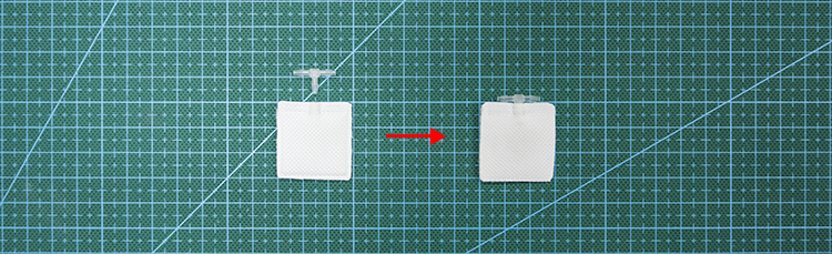
Prepare silicone tubes Silicone tubes is used inside of pneumatic network to make it inflate fast. In this step, we cut silicone tube into 2 sizes.
|

|
Heat sealing Using the technology of heat sealing, we can divide a long air column bag into a series of air chambers. In this step, silicone tubes were put inside of channels when sealing.
|

|
Seal This is the last step to finish the fabrication of pneumatic network. In this step, a plastics straight through connector was sealed inside of the channels with hot glue. |
Bill of Materials
Airbag
Air Inflatable Rolls Bag
Click here to buy.

Connector
Value Plastics Straight Thru Connector , 400 Series Barbs, 1/16"ID Tube
Click here to buy.

Silicone Tube
uxcell 1mm x 2mm Silicone Translucent Tube Water Air Pump Hose Pipe
Click here to buy.

Syringes
Syringes
Click here to buy.

Scissors
Scissors
Click here to buy.

Knife
Utility knife
Click here to buy.

Tweezers
Tweezers
Click here to buy.

Clips
Binder clips
Click here to buy.

Ruler
Steel Ruler 1m
Click here to buy.

Hot Glue
Hot glue gun and hot glue
Click here to buy.

Sealer
Cellophane bag sealer
Click here to buy.

Step 1: Prepare Airbags
Cut off a line of PA-PE to make airbags between two sealing lines.


Mark the points to be heat sealed. The rules can be detailed in here.

After finishing all the marks, draw a solid line at the position to seal the whole airbag.

Cut at the point 5mm outside from that solid line.

Thus, we get a marked line to make airbags.

Silicone tubes inside

Firstly, get 8 silicone tubes, 4.5 mm each: directly cut off those bits at the length of 4.5 mm,

Similarly, prepare 7 tubes of 9.5 mm in the same way.


Step 2: Prepare Silicone Tubes
Silicone tubes inside
Firstly, get 8 silicone tubes, 4.5 mm each: directly cut off those bits at the length of 4.5 mm,
Similarly, prepare 7 tubes of 9.5 mm in the same way.
Step 3: Heat Sealing
This page illustrates the main step in fabricating the pneumatic networks. In this step, the design scheme is implemented by heat sealing the marked points on the airbag column in last step. Notice that the sealer should be configured with a proper heat-up time in one press to ensure the quality of airbags produced.

Firstly, put all the silicone tubes into the airbag column.

Inflate some air into the airbag column to ensure the tubes' free movements inside.

Temporarily seal up the airbag column by a clip.

Next, we begin the heat-sealing from the inside end.

Select a 4.5 mm tube and move it towards the end.

Fix the tube along one side of the airbag column, and heat-seal it at the red-dotted line shown in the figure below.

Seal it again at the other red-dotted line. The result is shown below.

Then, successively heat-seal the 9.5 mm tube at the four dotted lines in the figure below, and we finish a loop of airbag pairs. Then, the loop is repeated 6 times, and we seal another 4.5 mm tube at the opening end.

Now, we finish the heat sealing of the pneumatic network composed of 7 long tubes (9.5 mm) and 8 short tubes (4.5 mm). The heat-sealed airbag column can be separated into 16 chambers, and each two adjacent chambers divided by a short tube forms a pair of airbags. The two pairs in this airbag column are divided by a long tube, and each pair is to be put inside a chamber of the manipulator's frame. Thus, one airbag column containing 8 pairs in total can be just put into one line of a manipulator segment (each segment has four lines and need four airbag columns).

Step 4: Seal
In this page we will finish the last step of making pneumatic networks: sealing.
Prepare the following materials and tools: a heat-sealed airbag column, connectors, a tweezer, heat sealer and a hot glue gun.

Below is the unsealed pneumatic network.

Use heat sealer to seal the airbag along the two red dotted lines. Notice that this needs two sealing operations with a 5 mm gap at center for air inlet.

Fetch a connector using a tweezer.

Evenly smear the hot glue around a side of the connector. Notice that we need a quick finish or the glue will cool down and become undeformable and incohesive.

Insert the connector into the prepared air inlet, with the smeared side towards the inlet.

Press the connection area using fingers to ensure air tightness, and wait seconds for the glue to coagulate.

Thus, we have finished a column of pneumatic networks. It can be inflated using syringes and its air tightness can be examined by inflation under water.

Another Implementation of Air bags
In this paper, we use another implementation of air bags, as shown below.
|
Assemble
This section contains detailed instructions for assembling honeycomb structure and pneumatic networks together to finish the fabrication of HPN manipulator.

|
|

|

|

|

|
When assembling pneumatic networks with honeycomb structure, we can fold the pneumatic network from every short tortuous and plug it into every single chamber of honeycomb structure. The GIF below shows the process of assembly.

The GIF below shows the deformation of HPN manipulator when inflated.
