Foam-based Soft Actuators
Foam actuators are a type of soft actuator that were originally developed in the Organic Robotics Lab at Cornell University. They are composed of an open-celled elastomer foam which is sealed with a nonporous elastomer.
The main advantage of these actuators is that they can easily be cast, cut, and even sculpted into 3D shapes, allowing simple fabrication of 3D soft machines. Examples of foam shapes are shown in the figure below.
Open channels and chambers for inflation are a requirement for fluidic actuators. Using other fluidic actuator fabrication methods often requires either difficult molding methods (such as lost wax casting) or complex assemblies of small actuators to form these channels. With foam actuators, the fluidic channels are already present in the form of the interconnected pore network.


Design
Actuator Components
Foam actuators are typically made of 3 components:
- an open-celled elastomer foam
- a strain-limiting layer
-
a nonporous sealing layer
Elastomer Foam
The elastomer foam can be custom fabricated or purchased as as finished product from a manufacturer. The key property is that the foam be open-celled (that is, contains an interconnected pore network) so that fluid may be transported throughout.
Custom foams can be made using any variety of foam-forming processes; however we had the most success using either a lost salt process or castable polyurethane foams.
The lost salt process involves mixing salt particles into a liquid elastomer (that is, before the elastomer has cured). After the elastomer has cured, the salt is removed leaving a porous elastomer. Castable polyurethane foams generate pores without any additives. These materials can be purchased as a two-part liquid systems. Once the two parts have been thoroughly mixed, they can be cast into a mold. As the polyurethane cures, it generate gas which forms the pores within the final cured elastomer.
Because foams of many different materials can be formed through the lost salt process, this method allows greater control of the foam mechanical properties and porosity. Polyurethane foams can be easier and faster to use as they require less processing.
Strain-Limiting Layer
Similar to other soft actuators, foam actuators require some form of regional strain constraint to direct the motion of actuation. The strain-limiting materials can often be embedded with the foam or the sealing layer.
Several materials can be used to locally limit strain including plastic mesh, wound fibers, or even just a stiffer elastomer. So long as the strain limiting material forms a region with a higher stiffness than the rest of the actuator, its motion upon inflation will be directed. This is explained in more detail below.
Sealing Layer
The final component of the foam actuator is the sealing layer. The seal should be a nonporous rubber and serves to make the actuator airtight (often, with the exception of an inlet port for pressurization). For foams made using a lost salt process, the seal can be composed of the same elastomer as the foam ensuring chemical compatibility between the materials.
Directed Actuation
The location and orientation of the strain-limiting layer directly determines the type of the resulting actuator. For example, a bending rectangular actuator is formed when a plastic mesh is embedded on one surface of the sealing layer. An extending cylindrical actuator is formed when the mesh is embedded in circumferential strips around the foam.


|
|
Fabrication
Elastomer foams can be made by any variety of foam-forming process, though to date, the lost salt process and castable polyurethane foams have shown the most promise.
When using the lost salt process, this tool is useful to calculate amounts of elastomer and salt to combine. By inputting the desired elastomer amount and volume fraction of salt (which is approximately equal to the subsequent porosity of the foam) as well as the elastomer and salt density, this tool outputs the mass and volume amounts of each component.

Formulation Tool (download link)
Below, two methods to fabricate foams using lost salt processes are described. The first uses ammonium bicarbonate, the second uses table salt. Whereas the ammonium bicarbonate foam-forming process is faster, the table salt process requires no hazardous chemicals.
Ammonium Bicarbonate in Silicone
This method of producing foams uses ammonium bicarbonate, (NH4)HCO3 (also known as ammonium hydrogen carbonate). Ammonium bicarbonate is useful as a porogen because it i) thermally decomposes readily and entirely above 50 °C, ii) yields easily managed products (water, CO2, and NH3) leaving the PDMS foam residue free, and iii) is inexpensive and readily available.
Of the decomposition byproducts, water is the highest boiling. Considering this, if ammonium bicarbonate is decomposed above 100 C, all of the byproducts will be removed as gases. We used a vacuum oven to remove the salt quickly. Depending on the part size, the ammonium bicarbonate was removed within 2-8 hours.
We selected Mold Max 10 PDMS (MM10; Smooth-On, Inc.) as the elastomer due to its low tensile modulus ( E ≈ 500 kPa) and large ultimate strain, which enables large deformations at low inflation pressures (typically Δ P < 70 kPa). Additionally, MM10 is beneficial as it exhibits a short room temperature cure (≈3 h) and is compatible with ammonium bicarbonate porogen since it cures via an organotin-catalyzed condensation reaction.
One important consideration when using ammonium bicarbonate is that it will significantly inhibit the platinum catalyst in addition-cured PDMS resins. This means that it should primarily be used with tin-cured PDMS resins.
Table salt soft foams manufacturing process
Materials:
- Ecoflex 00-10 Part A + Part B
- Table salt
- THI-VEX thickener (optional)

Manufacturing steps:
- Mix Ecoflex 00-10 Part A and part B 1:1 ratio, by weight;
- Add the table salt to the EcoFlex mixture according to the desired porosity;
Open cells porosity can be described as follows:
\(ϕ_p=V_S/(V_E+V_S )=(M_S/d_S )/(M_E/d_S +M_S/d_S )\)
Where:
VS is the table salt volume, [cm3]
VE is the total Ecoflex volume (Part A + Part B), [cm3]
MS is the table salt weight [g]
ME is the total Ecoflex weight (Part A + Part B), [g]
dS = 2.17 is the table salt density, [g/cm3]
dE = 1.04 is the Ecoflex density, [g/cm3]
- Manually stir the mixture to obtain an homogenous compound;
- Wait for 15-20 minutes;
- Sculpt or cast the soft foam;
To sculpt the desired shape, an additional of THI-VEX (Smooth-On) thickener (4% weight of part A) is needed, in order to increase the mixture viscosity. Directly add it once the salt crystals are homogeneously distributed in the mixture. Otherwise, it is also possible to partially cure the mixture for 20-25 minutes before sculpting. To cast the soft foam, just pour the mixture in the desired mold and wait until the mixture is cured (about 15-20 minutes). To speed up the curing, it is also possible to put the sculpted/casted mixture in the oven (15 minutes at 80°C).
Table salt soft foam casting:
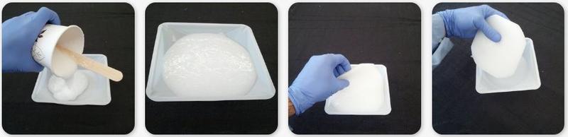
Table salt soft foam sculpting:

- Remove the salt particles after curing.
Once the mixture cured fully, it is necessary to dissolve the salt in warm water (~50°C) overnight. To speed up dissolution, an ultrasonic bath could be useful. In addition, it is also possible to periodically stretch the foams under water to increase salt-to-water contact. After drying the foam, we used compressed air (at flow rates accessible by computer keyboard air dusters) to remove any residual salt, which ensured an interconnected fluid pathway by breaking thin walls between closed cells (see also the following video)
|
|


Strain Limiting Layer insertion
The strain limiting layer allows the actuator to bend in a precise direction when the actuator is pressurized. We add a paper sheet (with the desired shape) as inextensible layer. We used paper because it is easily accessible, low cost, and can be cut to any shape using a laser cutter or scissors. As paper is porous, this layer merges completely with the sealeant elastomer while curing. Thanks to this manufacturing technique, the inextensible layer can be directly added while sealing the soft foam (see next step).
Foam Sealing
We used two different methods to form the external seal: painting and molding. Painting can be faster (especially for complex shapes) by eliminating the need to design a mold; however, it can result in an uneven seal. Molding enables a precisely designed, reproducible seal and thus was our preferred technique for blocking force test samples. This one-step seal cure avoids bonding issues between asynchronously cured seal layers, as opposed to the multi-step cure often used in traditional approaches. Though the foam and seal cure at different times, the bond is sufficiently strong for inflation due to the large bonding area available on the foam's porous surface.

Some examples of manufactured actuators with different sealings are shown in the following picture:

Castable Polyurethane Foams
It is also possible to form foam actuators using castable polyurethane foams. Unlike foams made from the lost salt process, these foams do not require additives to form pores. These polyurethanes are formulated to generate and retain gas during their cure which results in a porous elastomer foam. The advantages of using these materials is that they can be cast as a very low viscosity liquid (prior to foam formation) and that they generally attain high porosity foams (leading to rapid actuation). The Flexfoam-It series of foams (available from Smooth-On) are a great basis for these actuators. As with all of the foams described on this page, these foams can be combined with a sealing elastomer and a strain-limiting layer to form a foam-based actuator
Modeling
Modeling Airflow
We compared our experimental airflow measurements through the foam (described in the Testing page) to an Kozeny-Carman (KC) model for fluid flow through a packed particulate bed. The KC model relates fluid flow to key parameters as displayed in the equation below.
\(Q = {\Delta P \Psi^2 D_p^2 \phi^3A \over 180 L \eta (1-\phi)^2}\)
where Q is flow rate, ΔP is pressure drop across the sample, Ψ is PDMS spherical, Dp is the spacing between pores, Φ is sample porosity, A is sample cross-sectional area, L is sample length, and η is viscosity of the fluid.
Of these parameters, we directly measured Q, ΔP, A, and L from the airflow experiment measurements and sample geometry.
We used X-ray μCT to extract Ψ, Dp , and Φ for each of the tested foams. Using the freely available ImageJ image processing software with the BoneJ plugin (version 1.4.0), we determined the porosity, pore surface area, and average spacing between pores from the scans using the Volume Fraction, Isosurface, and Thickness functions, respectively. Since the foam microstructure is relatively similar to that of cancellous bone, the BoneJ plugin is a particularly useful software package.
From these measurements, we calculated the sphericity (Ψ) of PDMS from the following equation with measured values of PDMS volume (V) and surface area (S.A.) from BoneJ.
\(\psi = {\pi^{1/3} (6V)^{2/3}\over S.A.}\)
When input into the KC model, using no free parameters, the predicted flow rates are in close agreement with the measured rates through rigid foams. The soft foams, however, exhibited much higher flow rates than both the rigid foams and the flow rate predicted using the KC model. To determine the cause of this discrepancy, we compared µCT scans of the sample with and without air flowing through it. Visually, when air flowed through the foam samples, we noted that the foam cylinder deformed to create hemispherical surfaces in the direction of airflow. The µCT scans were consistent with this behavior in that they showed an apparent 12% increase in porosity when permeating at a 7 L min−1 flow rate relative to the porosity at 0 L min−1. We attribute the apparent increase in porosity to the expansion of pores in accommodating the strain of the hemispherical macroscopic deformation. Further verifying this phenomenon, our calculations showed that the porosity was highest in the center of the sample (the region furthest from fixed edges) and became incrementally less porous in regions closer to the perimeter. As the porosity is a heavily weighted parameter in the KC equation, we attribute the increase in flow through soft foams to this strain-induced porosity increase.
Testing
This sections describes testing that was performed on two material systems: ammonium bicarbonate with MoldMax60 silicone (available from Smooth-On) and the table salt with several silicones.
Ammonium bicarbonate foams: tensile tests and blocked force measurements
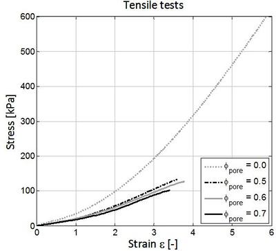
 To characterize the mechanical properties of the foam, we performed uniaxial tensile tests on samples of φ = 0, 0.5, 0.6, and 0.7 porosity (i.e., pore volume fraction) and measured the forces applied by the sealed actuators via blocked force measurements.
Tensile tests on the unsealed foams show a trend of decreasing elastic modulus as porosity increases (Adjacent Figure a). The average tensile moduli, measured at ε = 1, of the φ = 0, 0.5, 0.6, and 0.7 porous foams were E ≈ 508 kPa ± 28, 200 kPa ± 31, 83 kPa ± 6, and 48 kPa ± 19, respectively. The average ultimate tensile stresses and strains were σUTS ≈ 2.22 MPa ± 0.09, 0.40 MPa ± 0.02, 0.24 MPa ± 0.02, and 0.064 MPa ± 0.04 and εult ≈ 3.56 ± 0.22, 1.97 ± 0.10, 2.35 ± 0.09, and 1.58 ± 0.16 for the φ = 0, 0.5, 0.6, and 0.7 porous foams, respectively. The low variation within these samples (n = 3 for each porosity tested) indicates good repeatability even though the foams are stochastically structured. The data also show that all foams can stretch to ε >> 2 before failure; this elongation is essential to obtain large actuation amplitudes. Within the data, we also note that the pure ( φ = 0) PDMS has a higher ultimate strain, ε ULT ≈ 3.3, than the foam materials.
To characterize the performance of the actuators, we performed blocked force measurements on φ = 0.6 and φ = 0.7 porous samples. This measurement constrains bending actuators to a specific curvature (Adjacent Figure b) and measures applied force as a function of inflation pressure (Adjacent Figure c). Due to its lower modulus, the φ = 0.7 porous foam actuates at lower pressures however it also fails at ΔP ≈ 50 kPa. The φ = 0.6 porous actuator inflates to higher pressures (ΔP ≈ 80 kPa) without developing an aneurysm, and therefore applies a larger force.
Ammonium bicarbonate foams: air flow measurements
 Additionally, we characterized the airflow rate through foam samples, since this parameter dictates actuation speed. We measured the input and output pressures across a foam disc (radius, r = 1.25 cm and thickness, d = 1.25 cm) while measuring the air flow rate through the system.
To record airflow measurements through the foam, we used a custom-built acrylic cell to bond a cylindrical foam sample within rigid tubing (Adjacent Figure a). We then hermetically sealed the tubing using bolted end plates and rubber o-ring gaskets. We designed this mount to contain the applied pressure and ensure air permeated a constant foam cross-section. We then increased the pressure differential across the foam from 0 to 104 kPa (0 to 15 psi) while measuring the flow rate downstream of the sample. We fabricated both soft and rigid foam samples for this measurement: the soft, elastomeric foam was silicone (MoldMax60, Smooth-On; E = 2 MPa, reported) and the rigid foam an epoxy (System 3000, FibreGlast; E = 16 GPa, reported). Due to the detection limits of our instruments, we required the higher modulus MoldMax60 over MoldMax10 to attain sufficient flow rates for measurement. All foam-fabrication parameters and procedures were unchanged when using MM60 and System 3000 epoxy. As seen in the Adjacent Figure b, the soft foams exhibited considerably higher flow than the rigid foams. We also observed the expected behavior that for a given material, a higher porosity resulted in a higher flow rate for all applied pressures.
From these results, we attempted to model the airflow through the foam using established theory. Discussion of this model is located in the Modeling section.
Table salt foams mechanical tests: tensile tests and air flow measurements
To characterize the mechanical properties of the cured foams three different porosities samples have been molded: ϕpore=0.5, 0.6, 0.7. Then uniaxial, monotonic tensile tests (3 samples per porosity) were performed, according to the ASTM D412 standard (Zwick & Roell Z010, elongation rate of 50 mm min-1). As a reference, uniaxial tensile tests on pure elastomer (ϕpore=0.0) have been performed.
Towards predicting actuator inflation rates, flow rate measurements through foams with three different porosities have been performed. We molded 150 mm long cylindrical samples of diameter 25 mm and cut them into 15 mm lengths. We then glued the samples to the inner surface of rigid acrylic tubes with length and inner diameter of 25 mm using Sil-Poxy silicone rubber adhesive (Smooth-On, Inc.), leaving 5 mm of space above and below the sample. Next, we mounted each tube between two 3D printed caps and rubber O-rings to make the tube air-tight. The mount connected the encased sample to a pressurized air source with controllable flow rate. We measured the output flow rate as well as the pressures upstream and downstream of the foam to calculate the pressure drop (using H271A-005, Hedland Inc. and FLDA3422G, Omega Inc., respectively).

The flow rate measurements (in the pressures range of 0<∆P<100 kPa) demonstrate that ϕpore=0.7 foam has the highest flow rate, which we attribute to its higher porosity. The results show a nearly linear relationship between airflow rate and differential pressure. The sample-to-sample variability is likely due to the stochastic nature of the pore network and foam fabrication variables (salt crystal size, degree of foam stretching, and amount of air pumping to remove residual table salt). All porosities tested had a suitable flow rate for fluidic actuation, but foams with ϕpore=0.7 porosity seem to be the most suitable for soft machines because of their higher flow rate and greater ease of sculpting (due to their larger salt-to-elastomer ratio).
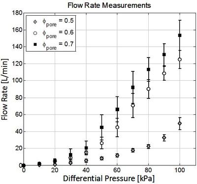
Table salt Soft Foam actuators tests: Blocked force measurement and Bending tests
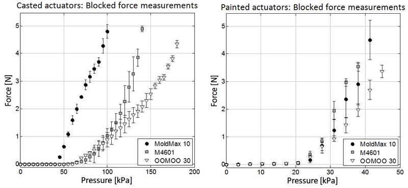
Blocked force measurements to characterize the actuators' applied force as a function of inflation pressure have been performed, for casted and painted actuators both. We tested ϕ pore =0.7 foams with three sealing elastomers, (Mold Max 10, M4601, and OOMOO 30) each of which has a higher hardness than Ecoflex 00-10. We used an acrylic sample mount to constrain the bending actuator (30x105x8 mm size) to a constant curvature and a balance to record applied force. We increased inflation pressure from until the actuator failed (i.e., sealing rupture or bursting). The experimental setup and the results of these tests are reported in the figure below.

In addition, using Elastosil M4601 as sealant, we were able to lift different weights by inflating a similar actuator in accordance with the actuation force measurements for the selected elastomer, as shown in the Video "M4601 Actuator force".
Through the blocked force tests, we observed that actuation force is related to the mechanical properties of the sealing elastomer, as expected. Specifically, higher hardness seals required greater inflation pressures to initiate actuation and to attain a given endpoint force. We recorded actuation initiation pressures of 45 kPa, 55 kPa, and 65 kPa and maximum actuation forces of 4.79N, 4.88N, and 4.34N for Mold Max 10, M4601, and OOMOO 30, respectively.
Using the actuator sealed with Ecoflex 00-10, we measured the curvature as a function of the inflation pressure. By using a very soft foam and seal, we obtained high bending (curvature radius r = 25mm) with low pressures (27.5kPa), as reported in the figure.

Case Study
Bioinspired Soft Fluid Pump
To demonstrate the utility of foam-based soft actuators, we fabricated a functional fluid pump with a biologically inspired external geometry, the heart.
|
|

|

|
The pump was designed from a digital heart model. We used this model to cast a shell of MoldMax10 (MM10; available from Smooth-On) elastomer foam surrounding the heart geometry (Below Figure a,b). After casting and adhering a nonporous PDMS top, we sliced the device in half (Below Figure c). We then bonded these two halves with woven kevlar/MoldMax60(MM60) composite to form two foam chambers and two liquid chambers (all isolated from each other) within the device. To finalize the device, we painted a MM60/chopped carbon fiber layer on the exterior of the device which directed all foam expansion inwards.

This pump is actuated pneumatically and is composed entirely of soft materials. As shown in the schematic below, the pump is composed of a pure MM10 top [A], pneumatic foam chambers composed of MM10 foam [B], a MM60/woven Kevlar barrier separating the left and right halves [C], pneumatic inputs [D], water-transporting tubing [E], and water chambers [F]. Green represents an inflated foam chamber while red represents an uninflated chamber. W1 and W2 represent valves in water transporting tubing; A1 and A2 represent valves in air transporting tubing. A red “X” indicates a closed valve.

The pump generates water flow using only a single air source and the timed control of four solenoid valves via a microcontroller (Arduino Uno). We used the microcontroller to attain a wide range of pumping frequencies.
The pump attains water flow by alternating between two states: (State 1) valves A1 and W1 are open, valve A2 is venting, and valve W2 is closed; (State 2) valves A2 and W2 are open, valve A1 is venting, and valve W1 is closed. In State 1, air travels from the source through A1 to inflate the left foam chamber. This inflation pressurizes the adjacent left water chamber generating water flow through W1 into the right water chamber. In this state, valve A2 is venting to accommodate compression of the right foam chamber as the right water chamber inflates. The microcontroller then switches all valves to State 2, causing the right foam chamber to inflate, pressurizing the right water chamber and causing water flow through W2 back to the left water chamber.
When pumping water at frequencies of 2, 1, and 0.1 Hz, we observed sustained output flow rates of 190 mL min −1, 370 mL min−1, and 430 mL min−1 at pressures of 20, 14, and 12 kPa, respectively. At the time of publication, the 430 mL min−1 flow rate is 80% faster than the previously highest reported rate from a soft pump.
While pumping, the water flow is pulsatile due to the alternating inflation and venting of each foam chamber; however,throughout each inflation step, the flow is sustained.
Similar to other reported soft pumps, our design is a displacement pump that relies on compliant diaphragms. Unlike other pumps, however, our design does not employ combustion for inflation. Although combustion is a powerful energy source, the complexity in managing the safety and timing is complicated.
Soft Gripper Manufacturing
We manufactured a Y-shaped soft gripper with the table salt foam technique. The soft internal core was fabricated using table salt and Ecoflex 00-30 (available from Smooth-On) with a porosity of 70%. The strain-limiting layer was obtained by placing a Y-shaped paper sheet (cut with scissors). the gripper was sealed with Ecoflex 00-10 and an additional painted thin (about 2mm) OOMOO 30 layer. In this video an example gripper performs a pick and place test.
|
|

Soft Block Actuators examples
With this technique, soft actuators can easily manufactured with different shapes and sizes, just cutting a unique soft foam in different parts. In the picture below there are some examples of different size block actuators while bending.

Downloads
| silicone_foam_formulation_tool.xlsx | 10 KB |