Integrating Fibers in Robotics Using Automation
Motivation: Fibers are important for robotic articulation, actuation and sensing, but adding fibers is a bottleneck. When small numbers of robots are produced for research or by experimenters, the job is usually done by hand.

(examples of running fibers in robotics by hand bottleneck)
(a) Fold-flat bike helmet assembly
|
|
(b) eNable prosthetic hand assembly
|
|
(c) Articulated dragon model assembly
|
|
In soft robotics, fibers control the direction a soft actuator can bend. When a non-stretchable fiber is embedded in one side of a soft inflatable actuator, the actuator curls toward the fiber side. When a fiber is used as a “tendon” to pull on a soft structure, lifelike organic motions can result -- as in this simple example of a soft silicone tube with a thread inside:
Automating the fiber installation task will not only save time and increase uniformity, but will expand the materials available for robotics because of the huge variety of available fibers. Manufacturing techniques like laser cutting and 3D printing set strict tolerances for the types of materials they can process; few labs have lasers that can cut metal. Many materials either don’t melt in a filament-based 3D printer nozzle, or get damaged and lose functionality. Sewing and embroidery do require a thin, strong and flexible thread, but don’t take it far from room temperature. All the materials designated “thread” in this image can be sewn directly, and we have developed sewing-based methods to handle the thicker and softer fibers. Because the water-soluble polyvinyl alcohol sew-able stabilizers and soluble threads used for embroidery don’t interfere with silicone curing, the patterned fiber arrays are easy to transfer to materials used in soft robotics.

(Fibers that can be used for soft robotics projects)
Background
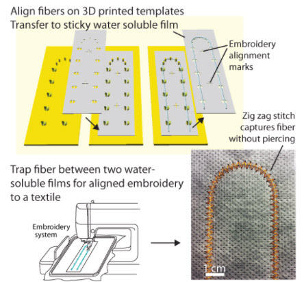
In this tutorial, we demonstrate methods to use a consumer embroidery machine for the fiber routing and attachment problems in 2D and give application cases with different fiber types. We provide a new plugin for a popular, open source vector drawing program (Inkscape) that outputs the PES format used by low-cost Brother embroidery machines, and show how to adjust the file so the patterned threads can be aligned to other parts.
People who have never used a sewing machine before have used these methods successfully. However it helps to know what's going on with the thread. In both a regular ("lock-stitch") sewing machine and an embroidery machine, there are two threads. One comes from the bobbin - a small spool under the fabric, and one thread comes from the needle above the fabric. Here is an animation on YouTube by Design Squad Global:
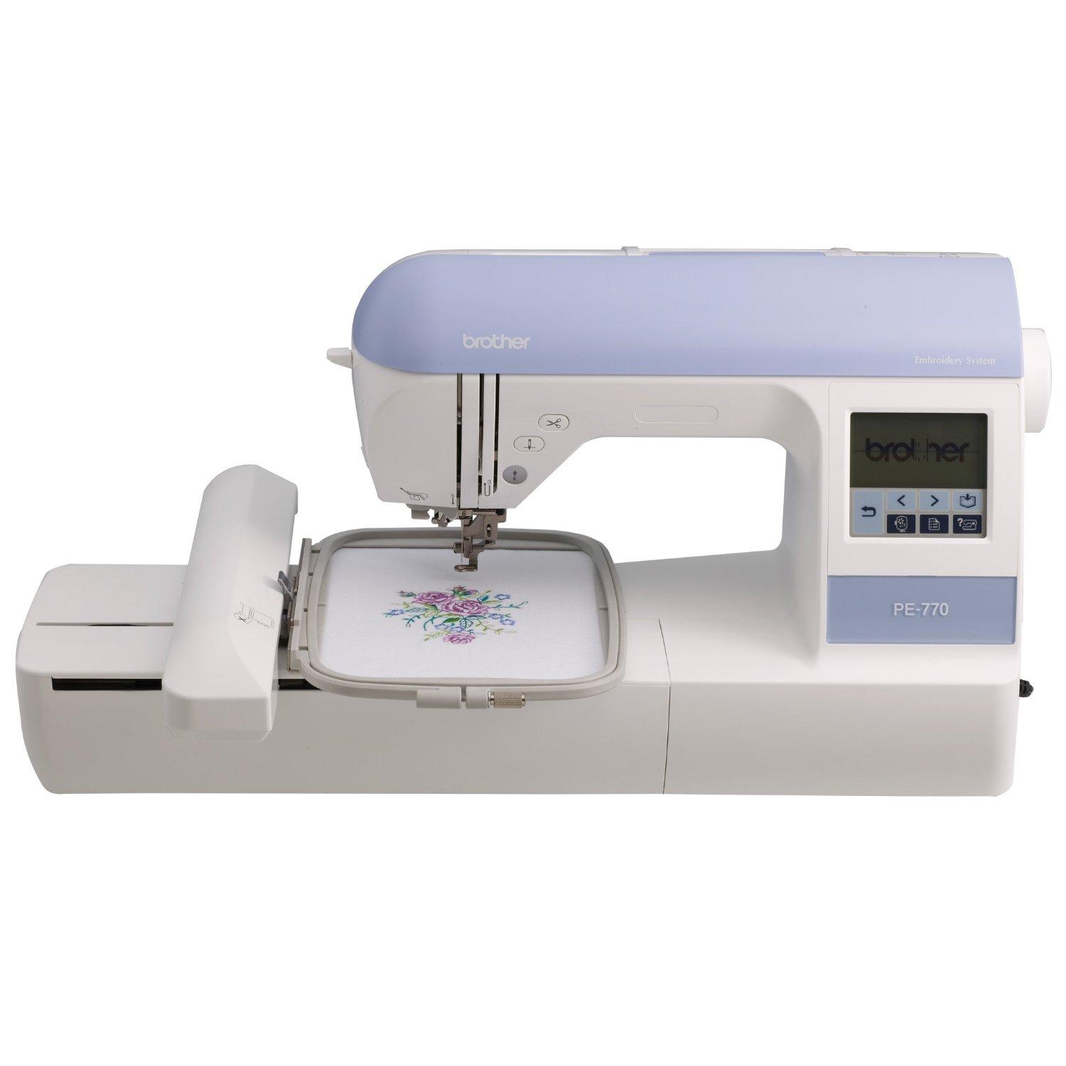
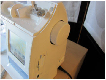
In an embroidery machine, when the needle lifts up, a computer-controlled X-Y stage moves the fabric to a new position and a pattern develops. Entry-level embroidery machines can carry out hundreds of stitches per minute! The embroidery demonstrations in this tutorial were done with two different Brother brand machines: the PE-525 with a 4x4 inch (10x10 cm) embroidery area and the PE-770 with a 5x7 inch (12.7x18 cm) area. Software and alignment steps were the same for both of these machines; the PE-770 has a little more ability to adjust stitch speed and thread tension:
We also show an example using a regular non-embroidery sewing machine with a couching foot to capture thick fibers. These were done on a Brother innov-is 80 machine. The benefit of using one brand of machine is that most of the consumable parts are interchangeable, especially bobbins. However, these techniques could be adapted to any brand of machine.
Design
This design overview gives examples of fiber-embedded robotic structures from our work. One set of structures is made by inserting fibers into thin parts or textiles, and another is about incorporating fibers into thicker 3D printed and machined parts.
See details about fibers installed in a sheet or within a 3D printed part in the subsequent pages.
Fibers Installed in a Sheet
Fibers can be used for articulation, sensing, and actuation in thin robotic parts (<1mm thick).
For example, we used conductive threads to add soft electromechanical switches to a bendable, laser cut polymer sheet using an embroidery machine.

Here is a hinged-plate structure with threads as hinges produced by our aligned embroidery method. The magenta threads are hinges that hold it together, while the white threads heat-shrink to lock in the folded shape. These fibers were installed in pre-cut planar pieces using water-soluble materials to hold the parts in place during sewing.

Aligned embroidery can also install functional fibers into soft materials such as elastomers and textiles. In this tutorial we show how to align an optical fiber along a path in a soft material.
Fibers Installed in a 3D Print
Fibers can also be installed in thin 3D printed parts using aligned embroidery. Here an array of thin squares was hinged together with embroidered threads, then 3D printed pyramids were added on top. The resulting part is more flexible than an all 3D printed part would be.

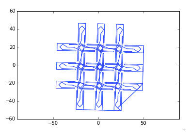
But how can we integrate an embroidered fiber layer into a thicker part? At a height greater than the embroidery machine can accommodate (~5mm)? This tutorial demonstrates how to laser-cut holes in a water soluble stabilizer to allow upper layers of a print to fuse with parts below the fiber layer. In these test structures, a fishing line (4 lb tensile strength) goes around and through holes in printed features. At some locations, the fishing line is deliberately trapped between the print layers, creating an anchor point. These test structures contain the basic ingredients for a robotic structure such as a 3D printed grasshopper leg with tendons and a hinge.

In the above figure: Workflow for inserting a fiber layer in a 3D printed mechanical part. Different fiber paths pass through, around and within 3D printed features. a) The needle locates alignment marks on a laser-cut water soluble sheet, and an aligned embroidery pattern (inset) is generated. b) The pattern is embroidered and c) inserted at a pause point in a 3D print file (inset). d) Before and e) after dissolving the water soluble sheet and freeing the hinged 3D printed features.
Fabrication
This section covers our aligned embroidery project and shows how to use it in two example projects: a thick fiber captured in a U-shape under a zig zag stitch in a sheet, and a thin fiber integrated into a 3D printed part. We also cover how to produce coiled fiber actuators in lengths compatible with sewing and embroidery.
Read more about the fabrication process used in the subsequent pages
Bill of Materials
UltraSolvy: This thick, translucent material is sewable and compatible with laser cutting. It is made from polyvinyl alcohol (PVA) and dissolves in water.
Sticky Fabri-Solvy: This water-soluble sticky PVA sheet has the texture of a paper towel (but is stronger) and can also be laser cut. Peel off its backing to attach thin parts for aligned embroidery.
Water-soluble topping: This thin, clear, textured material is sold to prevent embroidery from sinking into fluffy fabrics like towels. Sprayed with adhesive, it can trap parts in a sandwich for embroidery, while still letting you see through to the alignment marks.
PVA glue: Fibers can be coated with this water-soluble glue by pulling them through a tube with the glue in it. This coating can make it easier to attach low surface energy fibers like silicones to the Sticky Fabri-Solvy and other adhesive surfaces.
Wash-A-Way thread: A PVA fiber that can be sewn as needle or bobbin thread. It can hold your fiber in place temporarily during polymer casting.
StretchMagic: This stretchy urethane fiber can be used as a waveguide for red and infrared light.
Alignment Process
How to create an aligned embroidery file from Inkscape and run it on the Brother sewing machine. This is done using our Inkscape extensions.
1. Generate the x-y coordinates
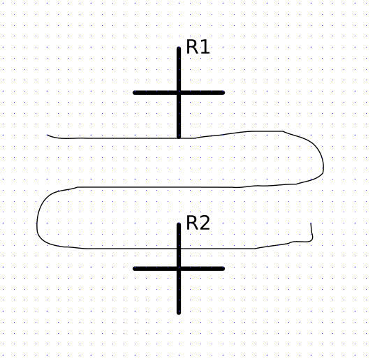
Generate the x-y coordinates using Inkscape (https://inkscape.org) to draw a path. If you need to do alignment with other features such as laser-cut holes in a part, the embroidery path can be placed alongside a drawing of those features. Make sure that both the drawing and the laser-cut have the same pair of alignment (registration) marks. We use two "plus" shaped symbols (+) on a horizontal line approximately 9 cm apart. These registration marks are created using the Registration Marks inkscape extension (Extensions -> Soft Robotics -> Registration Marks...)
2. Create the laser-cut (or 3D printed, or machined) item by exporting the part from Inkscape.
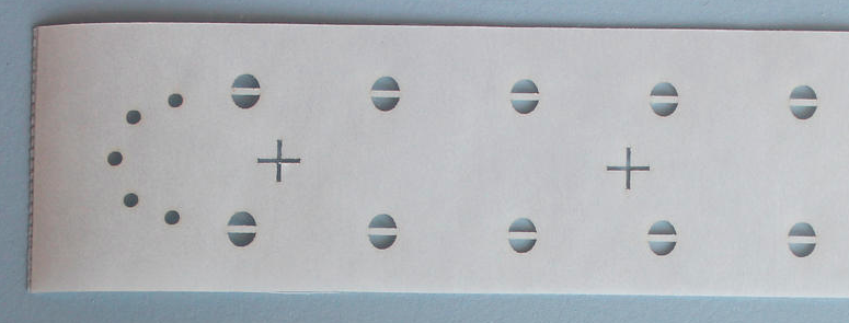
Be sure to include the alignment marks so they are printed, cut or machined at the same time. The part needs to be thin enough to go into an embroidery hoop (~5mm or less) and, if it's a hard material like a printed circuit board, the sewing holes need to be large enough for the needle to go through (typically 1 mm or greater). Here are several examples of good alignment marks in different types of parts:
The thin part below was cut into a piece of water soluble Sticky Fabri-Solvy for transferring a fiber into a soft material. The alignment marks were cut at the same time as the rest of the part.
This part had two purple alignment crosses printed at the same time as the thin 3D printed mechanism. Both were printed onto a piece of Sticky Fabri-Solvy, sticky side up.

In this printed circuit board (PCB), the alignment marks are small holes at the left and right along the center line of the PCB. The alignment marks were made at the same time as the PCB’s other features.
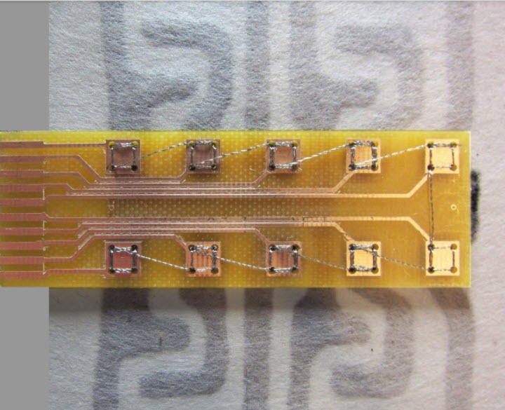
Both the PCB and the purple 3D printed part were too thick for the sewing needle to pass through without bending, so all sewing holes needed to be greater than the needle diameter (~1mm depending on needle gauge).
These thinner beams (~ 0.125 mm thick Mylar) were okay for the needle to punch through. Alignment marks were cut into the center beam at its left and right sides when the beams were laser cut, illustrating how several parts can be aligned on one part as long as they stay in registration with each other. The beams were attached to a piece of Sticky Fabri-Solvy, and surrounded by a fabric cutout to keep the Sticky Fabri-Solvy from interfering with the hoop.
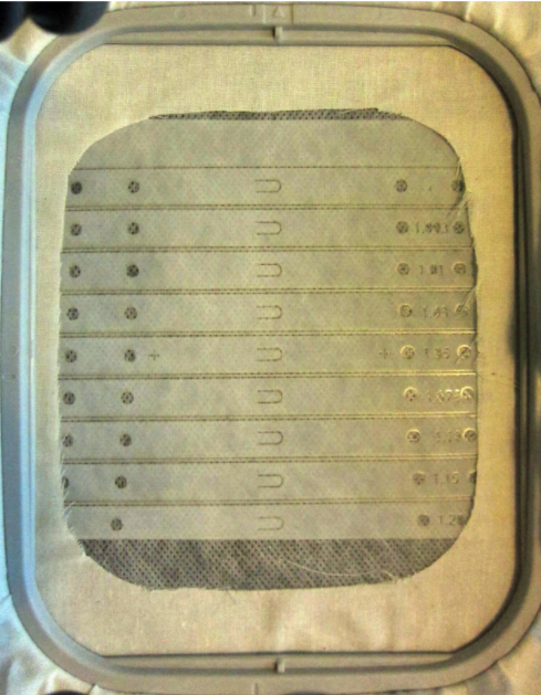
The UltraSolvy material we will show in the following pictures is a water-soluble material that can support a fiber layer in a part, and it is thin and soft enough to be punched through with the needle. To cut it on a 40 Watt laser (Epilog Mini) we used vector cutting at 25% power and 100% speed. It needed to be supported on an acrylic slab so the laser could focus. Similar laser cutter settings worked on StickySolvy, a paper-like water soluble stabilizer with an adhesive coating and wax paper backing; no acrylic support was needed.
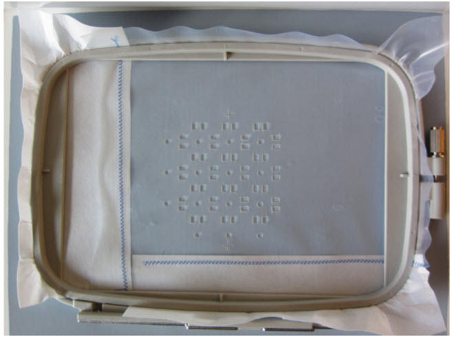
3. Install the part in an embroidery hoop.
The hoops come with a clear plastic template. The grid lines on the template can help get the alignment marks approximately centered to within ~ 5mm in x and y. We can reduce the alignment error to less than 0.5 mm using software. If using a laser-cut part, printed circuit board, or thin 3D printed part, stick it to a piece of Sticky Fabri-Solvy. Then, put a thin piece of water-soluble topping over it. You can use some spray adhesive to stick it to your parts if needed. The water-soluble topping will sandwich the thin parts in the hoop, prevent problems with the Sticky Fabri-Solvy sticking to the hoop, and still allow you to see through the material to the alignment marks. If your piece of soluble material is too small for the hoop, you can enlarge it by sewing on some additional pieces of fabric to cut off later.
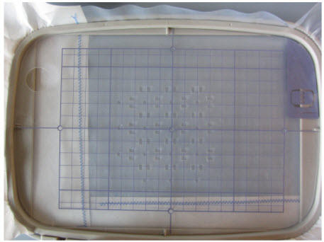
Use a template to get it close to the center, but not perfect.
4. Install the hoop in the embroidery machine and load up one of the small built-in patterns using its LCD interface.
You will be using this dummy pattern to steer the needle around and locate the alignment marks.
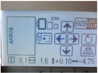
5. Locate the alignment mark positions.
Using the LCD, hit "adjust" and move the needle to the left alignment mark. The arrows on the screen of the PE-525 and PE-770 will let you move in 0.5 mm increments. Write down its x-y coordinates, which will be shown on the LCD in centimeters. You can use the wheel on the far right of the machine to lower the needle down to the fabric and make sure you have the best estimate for the location; if it looks like the center of the alignment mark is halfway between two increments, you can calculate the difference for an even better result.
You can lower the needle with the wheel at the right of the machine. However, be sure to raise the needle again because if you don’t, the machine won’t let you move the x-y stage.
Do the same for the right alignment mark and write down the coordinates. Then, you can hit the back arrow to discard the dummy pattern.
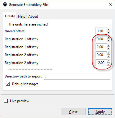
7. Use the Inkscape plugin to generate an aligned pattern
Back in Inkscape enter the coordinates you measured and export a .pes embroidery file. The plugin uses the drawn and measured alignment mark coordinates to rotate and translate the embroidery pattern so it will line up with your part.
8. Move the .pes file to a USB stick (for PE-770) or use the USB interface cable (PE-525) to upload the file to your machine.
It's best to have a folder with only your new file inside, and no others, because the files can look very similar-- especially if you are making several parts and each .pes file is the same pattern with slightly different alignment.
9. Check that your fiber is ready to embroider.
A functional fiber usually works best as bobbin thread, but some fibers such as thin fishing line or conductive thread can be run through the needle. If you forgot to load the right bobbin, you can remove the embroidery hoop, replace the bobbin and snap it back on without having to redo the alignment procedure.
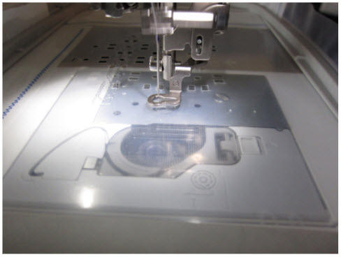
10. Lower the needle and press the start button above the needle.
No need to adjust or align the pattern. If the thread breaks or something goes wrong, you can press the stop button and use the LCD interface to back up a few stitches.
We highly recommend some practice on hooped paper printouts of your parts before trying it on the real thing!
Working with Thick Fibers
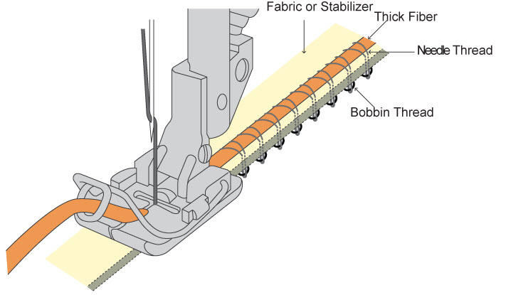
Thick fibers are some of the most interesting and useful materials for robotics. They include tubes, thick elastics, plastic optical fibers, and resistive stretch sensors. A fiber that is too thick to pass through the needle can still be used as bobbin thread; others have developed a sewing-based method to cast wires and tubes into polymers using them as bobbin thread in a regular sewing machine, with water-soluble thread in the needle. When the bobbin thread is much thicker than the needle thread, the thicker bobbin thread stays on one side of the material, which is an advantage for systems like fiber optics that need to avoid sharp bends.
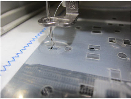
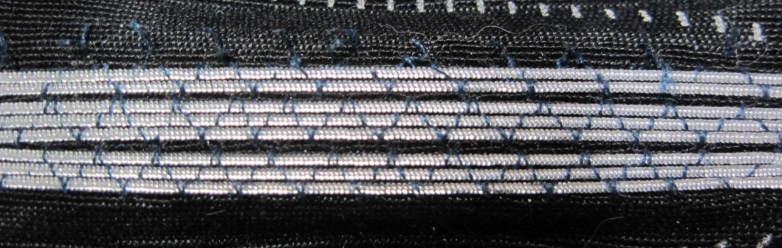
This fiber has a diameter of 0.5 mm. It was dispensed from the bobbin and is too thick to get pulled through the material by the white thread, so it stays on one side in an embroidered pattern.
However, fibers thicker than about 1mm diameter begin to get caught in the bobbin case. For scale-up, these thick fiber patterns can be transferred to textiles or water-soluble stabilizers using industrial machinery, for example, the large-scale specialized embroidery systems that install heater wires in car seats. There is a path to scale-up, but robotics labs need rapid prototyping alternatives. To capture these fibers using sewing, we can run a zig-zag stitch over them. The zig-zag can be made from a permanent thread or a water-soluble one; soluble threads allow you to transfer your thick fiber into a resin or silicone. We illustrate two methods: sewing with a couching foot and templated embroidery.
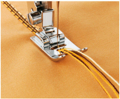
1. Sewing a thick fiber with a couching foot
Most regular non-embroidery sewing machines can be equipped with a couching foot. This accessory usually costs less than $10 USD and has a guide for one or more fibers. You set the machine to do a zig-zag stitch wider than your thick fiber, and the couching foot takes care of putting your fiber(s) at the center of the stitch so they don't get pierced. The disadvantage of this method is that it does not work with an embroidery machine's X-Y stage, so if you want to install the fiber along a complex path you have to steer the needle along the path by hand.
2. Trapping guided fibers under a zig-zag stitch using an embroidery machine
In this section, we describe how to attach a thick fiber along a path in the embroidery machine. This method allows the fiber to take computer-controlled curving paths. The Inkscape plugin can generate a zig-zag stitch along your path, so the problem becomes aligning the fiber’s temporary pattern to a pair of registration marks.
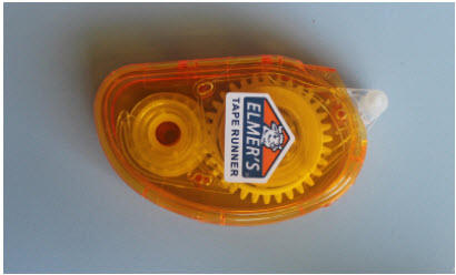
A simple way to do it is to print out the path and marks on a transparency. Then, use adhesive (an Elmer’s double sided tape roller works well) to lay down the fiber along the path manually. If it’s being transferred into a silicone, it may not be necessary to capture it in a zig zag stitch; just pour the silicone on top. The double sided tape was used to manually route a polyurethane optical fiber (1.8 mm Stretch Magic) along a path traced on a styrene sheet.
The tape is clear so you can see the guide lines underneath, and sticks well to urethane. Silicone was poured on the urethane fiber to encapsulate it; the final device can be used as-is or peeled off. The tape did not interfere with curing of Wacker M4641 silicone.
However, laying down a fiber on traced or printed lines can lead to a slow and hard to reproduce alignment process. And, the sticky tape won’t work as a permanent part of a stretchable device. We developed small 3D printed cleats to guide the fiber along with a process to transfer the aligned fiber to other materials. These guides stick through laser-cut holes in a water-soluble adhesive sheet as shown:
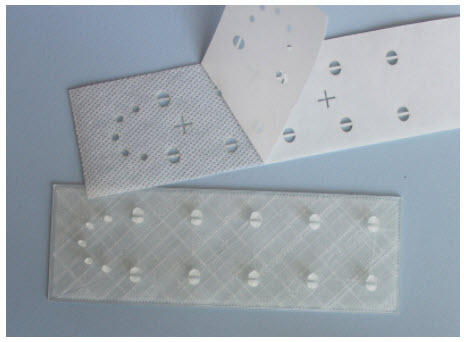
Top: StickySolvy laser cut with alignment marks. The backing is partially peeled off. Bottom: a 3D printed guide that works with the sticky sheet. Both the 3D printing file and laser cutting file are available in the Downloads section.
The StickySolvy sheet is laid on the template sticky-side up so fiber can be guided on a curving path in registration with the alignment marks.
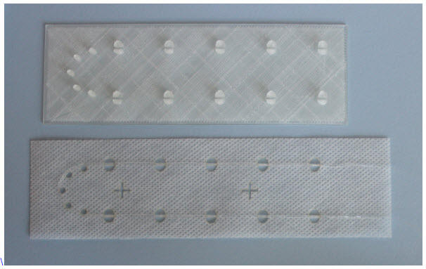
When the StickySolvy is removed from the template, the fiber and alignment marks go together. The sticker can be attached to a soft material for capture by an aligned zig-zag embroidery pattern following the procedure in the previous Alignment Process section.
3. Modular method for making large-area fiber alignment guides
What if you want to use the guide method for thick fibers, but do not have a large enough 3D printer (or enough time) to print a base the same size as your embroidered pattern? We are developing a modular method that works with a laser-cut base and drop-in 3D printed octagonal pegs to hold the fiber as it is being attached to the sticky embroidery backer. The advantages here are that it is very fast to laser-cut a wood or acrylic template, and the small 3D printed pegs are reusable from pattern to pattern. Then the backer can be placed in a hoop and embroidered using the methods above.


Adding a Fiber Layer to a 3D Printed Part
This section shows the steps to put a fiber layer partway through a 3D printed part. It requires a fiber layer to be pre-installed in a laser-cut water soluble sheet, and a 3D printed file that matches the laser-cut holes plus the ability to pause the 3D printer at a specific height in the print. The fibers in the sheet can be thick or thin. This method could be used to add tendons or actuators to a 3D printed part in patterns that are too tedious to install manually, or in places that would not be possible to reach after the 3D print is finished. Files for this example are available in the Downloads section.
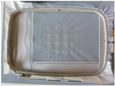
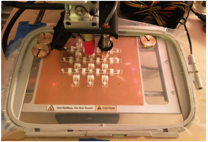
1. Cut water-soluble UltraSolvy and align the embroidered pattern to it using the steps in the Alignment Process section.
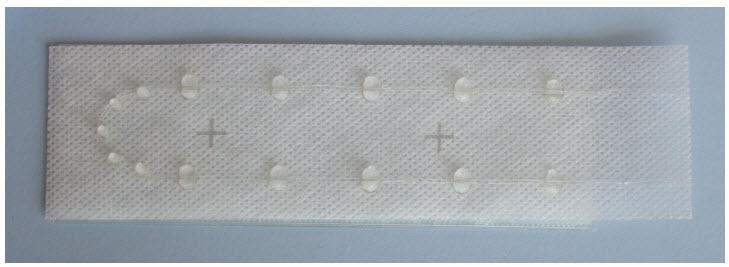
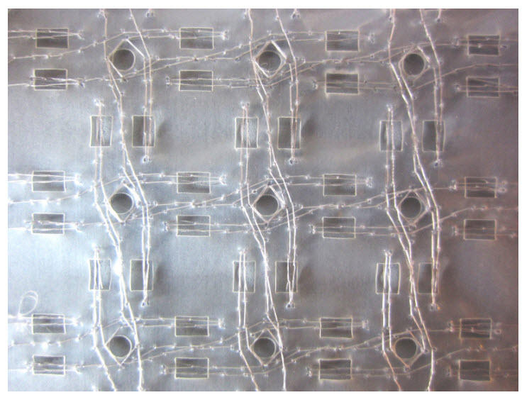
In this example, the needle thread is 4-lb polyethylene fishing line (It works best with these machines to use a dark rather than clear line because the thread-break sensor may not see the fine clear line). The bobbin thread is Wash-A-Way water soluble thread. The pattern here is slightly off center and rotated to match the locations of the UltraSolvy alignment marks.
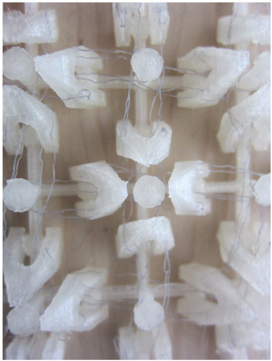
In the resulting pattern, most of the fibers pass around the holes but a few cross through. These crossing fibers are intended to be captured between layers of the part, anchoring the fibers down after the UltraSolvy is washed away. Fibers also wrap around posts (the circular hole) for reversing direction, and pass through cutouts in the part, performing tasks similar to tendons in the body.
This laser-cut file was obtained by slicing this 3D design at a height of 7 mm (approximately halfway through its thickness).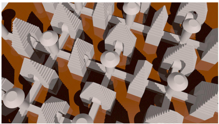
2. Print the part and install the fiber layer at a pause point
We used Octoprint software to pause the 3D printer (PrintrBot Metal with heated bed) at 7 mm. The material is PLA printed at 190C. After pausing, the print head was moved to the corner, and the fiber layer (still in the hoop) was hooked over the partially printed features and weighted down. Then the print was resumed.
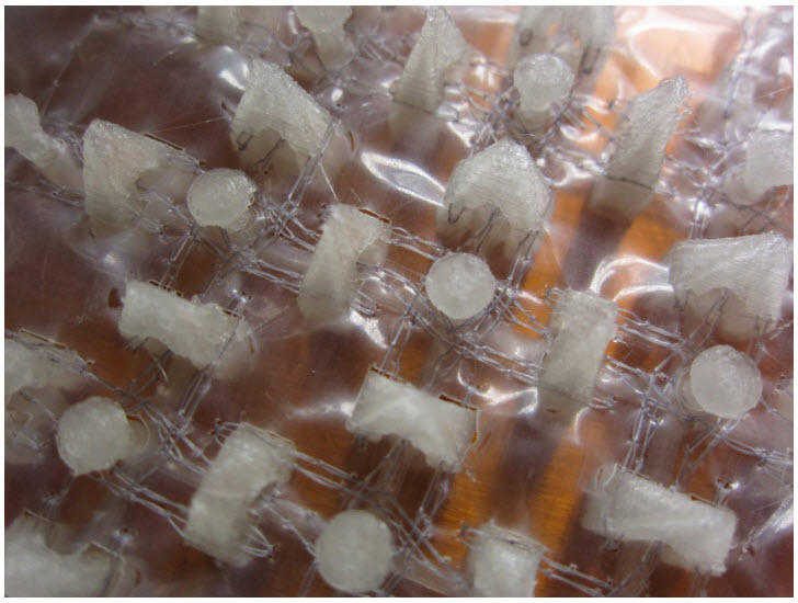
3. Wash away the UltraSolvy in hot water.
After washing away the UltraSolvy, the fibers were anchored in place. The hinged flaps were moved and fibers were observed to connect flaps along the intended routes.
Continuous Coiled Actuator Fabrication
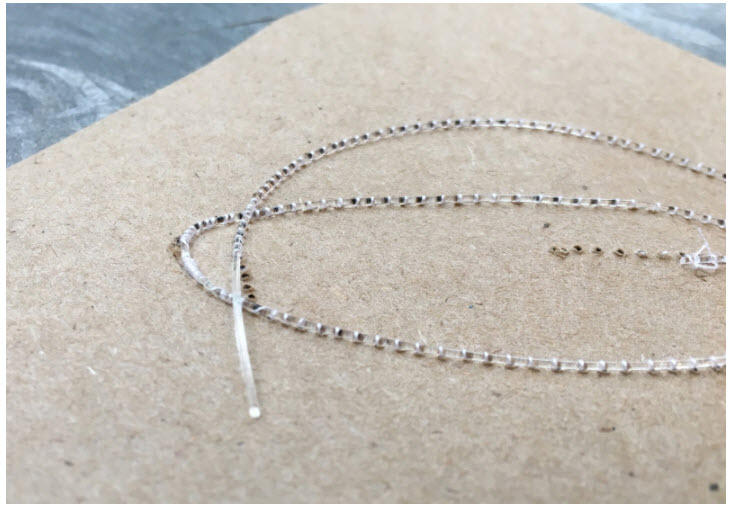
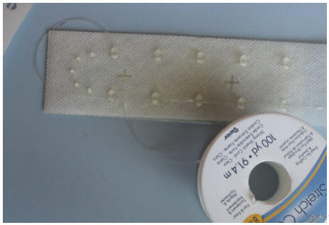
Coiled polymer actuators have become increasingly popular since their introduction in 2014 by the Baughman group, but most tutorials show how to produce short segments. To produce a fiber that could work with the sewing and embroidery equipment in this tutorial, we used a slip clutch from Dynatect (part PAO16-4-4) to dispense the fishing line under controlled tension from a spool that was rotated to twist the fiber onto a take-up spool so that continuous lengths (1m and greater) were produced. These coils, made from 8-lb nylon fishing line, have an approximately 1mm diameter and can be run through the sewing machine couching foot.
The slip clutch prevents the black spool at the right from spinning freely around its axis, applying enough tension to keep the coiling conditions at a steady state. The location of the coiling front is controlled by the speed of the take-up motor (left) and the speed of the coiling motor (right). The image below shows coiled fibers attached to a stretchable fabric by the sewing machine couching foot with a three-segmented zig zag stitch.
Testing
Stretch Tester
Here is a video showing the signal from a u-turn stitched stretch sensor on a stretchy surface undergoing some cycling.
The tester is built based on a linear translation stage from Actobotics: https://www.servocity.com/channel-slider-kit-a
We 3D printed the white clamps for attaching soft materials to the Actobotics parts. The design files (.stl) are attached below.
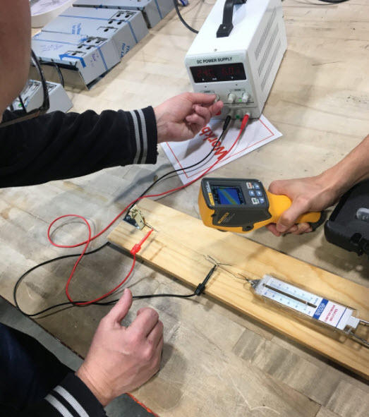
Measuring Actuator Force and Temperature
A 1-Newton spring scale and Fluke VT02 thermal imaging camera were used to monitor the temperature and force of actuators as they were powered from a DC supply at approximately 6V and 250 mA (1.25 W).
Downloads
Software
Inkscape embroidery alignment plugin including installation instructions
Files for 3D printed U-Turn fiber guide and laser-cut sticky material

Files for 3D print with fiber layer
