Design
Why we chose a spherical configuration
A sphere resting on a flat plane is in a state of neutral equilibrium and has the advantage of having unbiased tendency to roll in any direction when disturbed (Gupta, Singhal and Vasishtha, 1991). The state of neutrality also eliminates the need to deal with tripping and getting back up (as is the case with robots that have limbs).
How we intend to make the sphere roll
To induce rolling motion of the sphere, one common way is to exert a force on the sphere's exterior. However, a limitation of this method is that the sphere needs to be in contact with an external actuator that is responsible for the force. If we were to have any additional fixtures upon the exterior of the sphere, we would lose the unbiased freedom of the ball to move in any direction parallel to the surface it is resting on.
Another method is to displace the center of mass of the robot so that the sphere rolls in the direction of displacement. To execute this idea, a movable, heavy and dense mass is suspended in the middle of a hollow sphere. This heavy mass will be attached to an actuator within the sphere to bring about internal displacement of the robot's centre of mass, without altering the spherical exterior of the robot. Whenever the heavy mass is displaced in a particular direction, the center of mass and hence the robot would move in the same direction.
Why we chose to use diaphragm dielectric elastomer actuators (DEAs)
DEA is a suitable mechanism for inducing internal displacement of the heavy mass we intend to suspend in the hollow sphere, as suggested in the previous paragraph, because DEA is lightweight and will not significantly affect the concentration of mass of the robot at the dense mass. Dielectric elastomers (DEs) are electromechanical transducers able to convert electrical input into mechanical energy as manifested in actuation. In order to actuate, the DE film is painted on both sides with compliant electrodes. When voltage is applied, charging of the DE will induce maxwell stress in the film and it will be compressed in the thickness direction. Assuming that the DE film has unchanged volume (Incompressible), there will be planar expansion of the film. (Gu G. Y. et al., 2017)

Figure 2.1: Schematic of the internal center-of-mass-displacement system

Figure 2.2: Schematic of the heavy mass being displaced
The heavy, dense mass will be suspended at the center of the hollow sphere by means of rigid beams, which will be held in place by 2 diaphragm DEA actuators - the beams will be kept there by the compressive forces exerted by the diaphragms and the diaphragms will be in tension to balance that.
For the diaphragm actuators, DE film will be stretched over a rigid cylindrical film and held in tension because the pre-strained condition enhances the actuation and hence the displacement of the mass (Li B. et al., 2011). Acrylic VHB 4910 is the chosen DE because this material has high dielectric constant, produces good strain and can withstand shear (Adezif.com, 2017; Barnes A. et al., 2007; Plante J. S. and Dubowsky S., 2006).
Preliminary Model
The soft robot is a rolling spherical structure, similar to BB-8 (see 1. Background). To induce the rolling motion, we intend to produce lateral displacements of the sphere’s center of mass, thereby causing disturbances in the sphere’s state of neutral equilibrium.
Two diaphragm dielectric elastomer actuators (DEAs) are supported by rigid cylindrical frames and installed within a hollow, rigid sphere. A rigid beam is placed between the diaphragm actuators and a metal mass is attached to the beam using tapes. (see Figures 2.1.1a, 2.1.1b and 2.1.1c)

Figure 2.1.1a: Schematic of soft robot at rest

Figure 2.1.1b: Image of prototype at rest (front view)
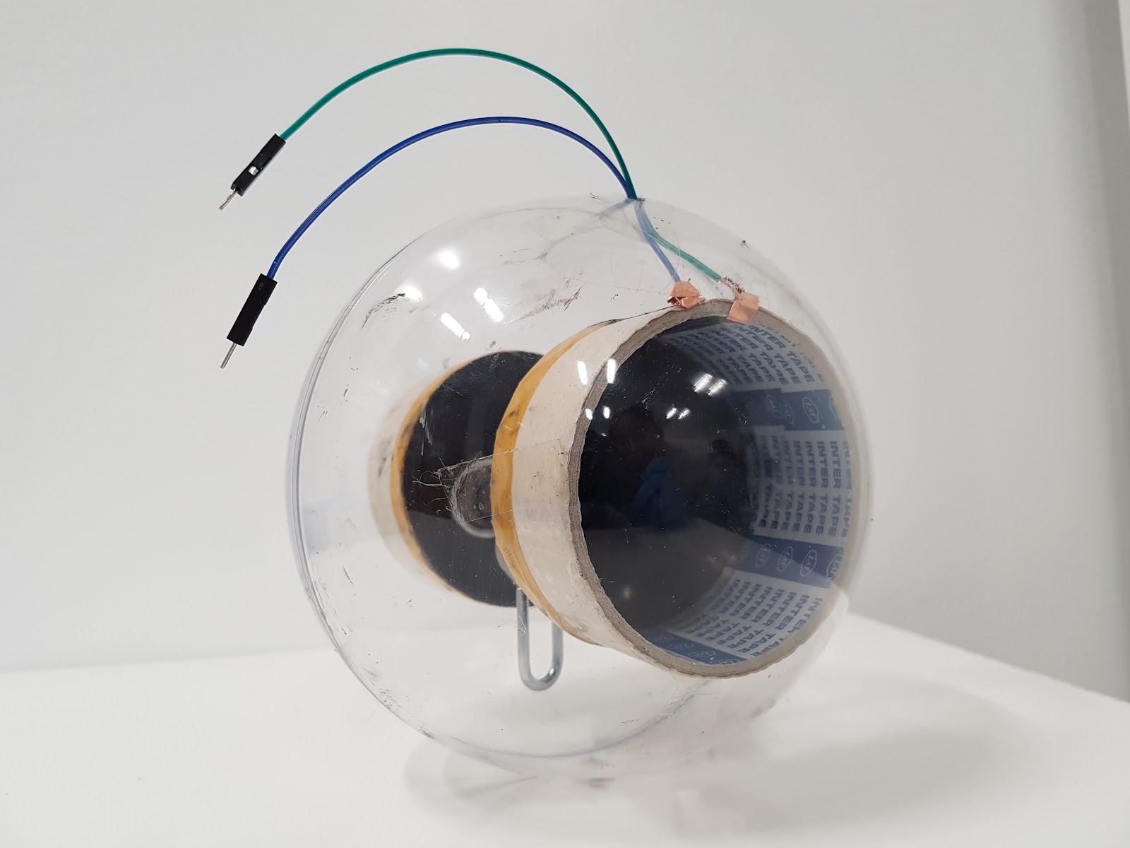
Figure 2.1.1c: Image of prototype at rest (side view)
When one of the diaphragms is actuated, the film of the actuated diaphragm increases in area and decreases in thickness. Because the rigid beam exerts some tension onto the two originally taut diaphragms, when one of the diaphragms bags slightly from the actuation, the compressive force from the actuated diaphragm on the beam would decrease. However, because the other diaphragm is still taut, there would be an imbalance in the forces exerted on the beam-mass so there would be a net force in the direction of the actuated diaphragm and the whole beam would shift laterally, away from the relatively taut film and towards the looser one. Consequently, the hanging mass would shift as well and the centre of mass of the entire sphere would be displaced. This causes the sphere to roll. (see Figures 2.1.2a and 2.1.2b)
Figure 2.1.2a: Schematic of disturbed soft robot
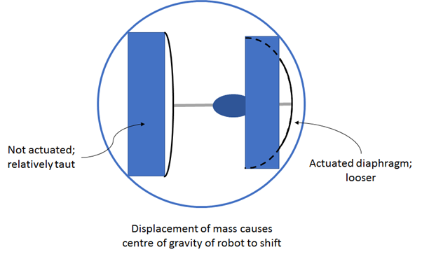

Figure 2.1.2b: Image of disturbed prototype
Electrical Input
The robot has 4 terminal points, namely, 2 pairs of positive-negative input and output. Using Arduino, we can control which terminals on the robot to supply power to, and hence, which diaphragm to actuate at any moment.
In this project, we are using an IR remote in conjunction with the Arduino for convenient control of the robot. This enables the user to actuate the diaphragms by clicking on the remote control without connecting and disconnecting the wires and/ or switches.

Figure 2.2.1: Image of electrical setup
Power supply
DEAs require high voltages on the order of kV to produce discernible actuation. To make the electronics set-up portable, the following are the components used:
-
Battery pack
-
Relay module
-
Variable voltage
-
Transformer

Figure 2.2.2: Pictorial of electrical setup

Figure 2.2.3: Schematic of electrical circuit
A voltage regulator and other components are employed to ensure that we do not oversupply power to the actuators. Too much power supplied to the actuators can burn the DE films.
From our readings, the robot requires about 3.53 V from the battery pack which would then be amplified by the transformer to around 7.06kv to actuate one diaphragm.
Controlling the system using IR remote and Arduino code
| Button | Action |
|---|---|
| PLAY | Actuate one diaphragm and induce lateral displacement of mass |
| 0 | Deactivate action from pressing "PLAY" |
| 3 | Actuate other diaphragm and induce lateral displacement of mass in direction opposite to that of pressing "PLAY" |
| 4 | Deactivate action from pressing "3" |
The following is the Arduino code to control wireless communication between Arduino and the IR remote:
| b-robot_arduino_ir_remote_communication.txt | 2 KB |
Strengths and Weaknesses
Strengths
- Since the individual components of the device are independent of one another, if one component is damaged, the rest of the device is still functional and only that one component needs to be repaired or replaced. For example, if one of the diaphragm actuators ruptures, only that actuator needs replacement but the other actuator and the rest of the sphere and electrical circuitry outside of the sphere can still be used.
- As the robot is spherical, it is, ideally, possible to design a robot that is able to roll along multiple directions by our proposed mechanism (after some modifications).
Weaknesses
- In-plane deformation of a diaphragm actuator results in corresponding out-of-plane displacement of the rigid beam connected to the actuator. This means that a pair of diaphragm actuators is associated with one direction of displacement of the robot's center of mass. Hence, the number of degrees of freedom of the robot's motion is limited by the number of pairs of diaphragm actuators installed in the hollow sphere.
- For our current prototype, the power supply and circuitry for electrical input are outside of the sphere and connected to the actuator by means of wires that go through holes drilled into the sphere. Having wires emerging from the sphere would impede the motion of the robot. (see Figure 2.3.1)

Figure 2.3.1: External wiring gets in the way of motion
Potential Modifications
Improve the robot's ability to move in multiple directions
An ideal sphere in a state of neutral equilibrium is equally capable of translating in any direction parallel to the flat plane or surface upon which it rests. To capitalize upon the robot's spherical shape and achieve a greater number of degrees of freedom in translational motion, the metal mass can be suspended by four rigid beams whereby the joints between the beams and the mass are able to rotate such that the motion of the mass can be controlled in 2 directions as shown in Figure 2.4.1.

Figure 2.4.1: Schematic of the modified soft robot at rest
Actuation of one diaphragm will cause the sphere to move in that particular direction. Thus, the modified robot is now equipped with 2 translational degrees of freedom and can move forwards, backwards, left, right, and diagonally.
Figure 2.4.2 depicts 2 diaphragms in the modified robot being actuated at the same time, enabling the robot to move diagonally (a combination of forwards and sideways).

Figure 2.4.2: Schematic of the modified soft robot when being disturbed
Compactibility
External electrical circuitry can be modified to fit into the sphere and will be concentrated at the center of mass of the robot.