Fabrication
This section documents our fabrication process. It is divided into 3 subsections:
Actuator documents how we constructed a pair of diaphragm DEAs by hand.
Device Assembly describes how we installed the pair of diaphragm actuators in the hollow, sphereical exterior of our robot and connected the beam-mass to the diaphragms to create the internal centre-of-mass-displacement system. (Design, Preliminary model for more detailed explanation of the working mechanism)
Electrical Wiring describes how we connected the robot to the power supply and associated control system. (see Electrical input for more information on how we controlled the electrical power supplied to the robot)
Actuator
To fabricate the diaphragm actuators in our B-robot, we followed this procedure for each side:
-
Stretch a square piece of acrylic elastomer over a rigid cylindrical frame (see Figure 3.1.1)
-
Stick a bottle cap in the middle of the stretched film (see Figure 3.1.2)
-
Brush both sides of the stretched film with carbon powder (see Figure 3.1.3)
-
Stick carbon tape over both sides of the electroded film such that the tape extends over to the rigid cylindrical frame (see Figure 3.1.4). Connect the carbon tapes to copper wires using copper tape on the surface of the rigid cylindrical frame (see Figure 3.1.5).
-
Brush both sides of the electroded film with carbon grease for better sheet conductivity (see Figure 3.1.6)

Figure 3.1.1: Stretching the elastomer

Figure 3.1.2: Sticking the bottle cap

Figure 3.1.3: Applying carbon black
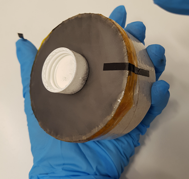
Figure 3.1.4: Sticking carbon tape
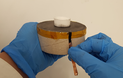
Figure 3.1.5: Sticking copper tape

Figure 3.1.6: Applying carbon grease
Device Assembly
The following account the steps we took to assemble the diaphragm actuators and other components of the device into our final prototype:
-
Drill a hole into each hollow rigid plastic hemisphere
-
Stick a rigid cylindrical frame (which is supporting a diaphragm actuator) onto each hollow plastic hemisphere
-
Pull the wires connected to the actuator's electrodes out through the hole drilled into the hemisphere
(see Figure 3.2.1) -
Tape a ~200 g mass onto the middle of a rigid wooden beam (see Figure 3.2.2)
-
Soften both ends of the wooden beam with Plasticine
-
Position one softened end of the wooden beam into the bottle cap part of one of the diaphragm actuators (which have already been installed within one rigid plastic hemisphere by this stage)
-
While supporting the wooden beam and mass atop one of the diaphragm actuators, position the other hemisphere over the beam such that the other softened end of the beam is directly entering the bottle cap of the actuator in the top hemisphere. Gently lower the top hemisphere until it connect and locks with the lower hemisphere to form a complete sphere. (see Figure 3.2.3)

Figure 3.2.1: One completed hemisphere

Figure 3.2.2: Centralized mass on rigid beam

Figure 3.2.3: Enclosing beam-mass in sphere
Electrical Wiring
Once through the assembly stage, the device would have conductive wires sticking out - positive and negative terminals emerging from each hemisphere. Extension wires were used to connect the wires from the robot to the power supply. (see Figure 3.3.1)
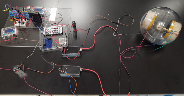
Figure 3.3.1: Electrical connection between device and power supply