Laminar Jamming Structures
 This work was supported by the National Science Foundation National Robotics Initiative Grant CMMI-1637838 and the National Science Foundation Graduate Research Fellowship Award 1122374.
Laminar Jamming Structures (LJS) are structures with thin layers enclosed in an airtight bag that can alternate between a highly flexible and a rigid state with a drastic increase in stiffness and damping when a pressure gradient is applied. LJS can also be used to simulate the deformation pattern of joints. Through laminar jamming, we enable soft robotic components to selectively exhibit mechanical properties similar to the ones in traditional rigid robots.
Actuation of LJS occurs by applying a vacuum to the airtight envelope, therefore subjecting the structure to a pressure gradient. Increased frictional interactions cause coupling between the layers, which dramatically increases the bending stiffness of the structure, since it behaves like a unified beam. In addition, at high loads, shear stress causes layers to slip, which results in dissipation of energy through dry friction. In short, when vacuum is applied, the structures can transition from a very compliant state to a more rigid and/or shock-absorbent one.

In this documentation set, you will find the fabrication methods used in a well-resourced fabrication laboratory as well as alternative methods that can be achieved in an educational environment. The fabrication process also enables the creation of LJS in different shapes and materials, expanding the possibilities of their use.
Bridging the characteristics of soft and traditional rigid machines through laminar jamming can increase the versatility and scope of the next generation of robots. This documentation set also includes case studies in which LJS were used in order to replicate joint structures and to aid a drone landing
|
Jamming Robots from Wyss Institute on Vimeo. |
Applications
In this section, we summarize the scope of the applications of laminar jamming structures, namely their adjustable stiffness, impact response and deformation alternation between discrete and continuous.
Some of the advantages of LJS are that they can be plastically deformed in their vacuumed state, and, if coupled with a soft actuator (e.g., with PneuNets Bending Actuators) can lock in arbitrary shapes after jammed. Below you see a video demonstrating these fundamental characteristics:
Laminar jamming can also effectively tune the dynamic responses of real-world robotic structures and systems. The impact response of soft structures (i.e., soft substrates with integrated jamming structures) can be tuned to conserve or dissipate energy as desired. For an incoming projectile with high kinetic energy, such as the baseball in the video below, relieving vacuum pressure from the jamming structures allows the energy of the projectile to be maximally preserved and the landing structure to return to equilibrium; on the other hand, applying vacuum pressure to the jamming structures rapidly dissipates the energy of the projectile and preserves the landing structure in a deformed state.
In addition, laminar jamming can be used in structures that simulate joints and can alternate between continuous and discrete deformation. The structures can perform pinch or wrasp graps, depending on the vacuum pressured applied to the LJS. With vacuum is off, the system displays continuous deformation with nearly constant curvature. When vacuum is on, the system exhibits discrete deformation with joints; rigid sections with low curvature are connected by flexible sections with much higher curvature, approximating the kinematics of a traditional articulated manipulator.
Design
 Laminar Jamming Structures are composed of stacked layers of flexible sheets, which are very compliant in their natural state. This feature enables the components to conform to complex shapes, allowing them to be used in biomedical applications and in a number of wearables. In addition, the choice of material and number of layers of these structures can be used to tune the desired stiffness and damping ability for specific applications.

The morphology of the LJS - meaning the structure, size and shape - can be easily changed during the fabrication process, allowing fast prototyping and a number of iterations in order to enhance the structure's performance. In addition, jamming structures have the ability to shape-lock, i.e., if they are deformed to a specific shape when they are in their natural, unjammed state and then vacuum is turned on, they can retain the deformed shape and resist static loading.
Furthemore, a number of other variables can affect the stiffness of the LJS, such as the choice of material, the thickness of layers as well as the total number of layers. For more information, refer to the Design Tool section.
Variation: Material
The properties of the material which will be enclosed in the airtight bag can greatly affect the behavior of the final jamming structure. Below, we present a number of reference values gathered from online databases and experiments of some materials that can be used in jamming structures. Please be aware that these values may need to be validated for your specific sample.
The overall performance will also depend on the number of layers used and the thickness of each layer, so a number of empirical tests may be necessary to ensure that the optimal mechanical properties for a specific application are achieved. The Design Tool section of this document can also provide useful inputs to guide design decisions according to specific requirements.
| Material | Young's Modulus (GPa) | Density (kg/m3) | Coefficient of friction |
| Paper | 5.5 | 800 | 0.5-0.7 |
| Polyester | 2 | 1052 | 0.2-0.4 |
| Steel | 200 | 7850 | 0.7 |
| Nylon | 3 | 1150 | 0.2 |
| LDPE | 0.4 | 928 | 0.25 |
| Polyurethane Foam | 0.003 | 480 | 0.38 |
Variation: Morphology
 The simplest shape used for laminar jamming is that of rectangular sheets, Nevertheless, even the simplest shapes can achieve a number of conformations due to the shape-locking ability of Laminar Jamming Structures. Shape-locking enables LJS to achieve an arbitrary configuration when they are in their flexible state, lock in place after being jammed and resist static loading. When these jamming structures are used with soft actuators, they can save power by requiring no control effort to preserve the apparatus's shape, even if the actuation input is turned off. Furthermore, soft machines with high material strain (e.g. Pneumatic Artificial Muscles) can be deflated after locking, mitigating the risk of catastrophic rupture.

|
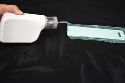
On the left, you see a demonstration of the shape-locking ability of Laminar Jamming Structures by coupling one of them with Pneumatic Bending Actuators (PneuNets). PneuNets are soft actuators which bend when pressurized, but they return to their original shape when the pressure is relieved. In the experiment, a PneuNet is attached to an LJS and pressurized to obtain a desired bending angle. The jamming structure is activated by turning on vacuum, thus applying a pressure gradient that causes the LJS to lock in its stiff conformation. As a result, even when the PneuNet is depressurized, the system preserves its shape with high fidelity.
In addition, departures from the traditional rectangular shape can increase the range of shapes that Laminar Jamming Structures can achieve. Below you see videos of interesting geometries obtained after a woven mesh and a plus-shaped jamming structure were actively pressurized and depressurized by turning vacuum on or off.


Fabrication: Laboratory
In this section, we will provide step-by-step instructions on how to fabricate Laminar Jamming Structures in a laboratory environment. Please refer to the Design section or the Design Tool for recommendations on design choices. We will additionally cover alternative methods of fabrication in the Classroom section, which illustrates accessible and fast methods of prototyping LJS.
The main goal in the fabrication of LJS is to obtain a component which is completely airtight - except for a small tube connection - and in which the enclosed material (here referred to as filling) is arranged in layers that are in contact with each other in all areas. The surface contact area between layers should be maximized, ensuring that the entire structure gets jammed .
An overview of the process is provided below:
- Set-up: Cut acrylic frame and filling material
- Step 1: Vacuum form TPE layer to the acrylic frame
- Step 2a: Heat press TPE case with filling
- Step 2b: Impulse seal TPE case with filling
- Step 3: Look for leaks and adjust tube connection

Bill of Materials
This section will give a list of items that are used in this project with selected links to suppliers.
Note: Many of the items listed are just examples and you can use your own discretion to substitute parts which are easier or cheaper to obtain.
Structural Materials


Thermoplastic elastomer (TPE) Filling material of your choice (list)


Tubing of your choice (here used 1/8'' TPU tubing) Optional: Tube connectors
Assembly Materials


Acrylic sheet PTFE thread sealant tape


PTFE surface protection tape PTFE sheet


Cutting tools Butyl sealant tape
Equipment


Vacuum forming machine Heat press


Impulse Sealer Vacuum source (laboratory or hand-operated)
Step 1: Vacuum Forming
Set up

|
Before starting the fabrication of your Laminar Jamming Structure, you may need to assemble an acrylic frame. An acrylic frame will allow the forming of your TPE envelope to the geometry determined by your frame, therefore creating a pocket that will fit thick structures and will prevent the bag from exerting forces on the filling material. If you believe an acrylic frame is not necessary for your LJS, please proceed to Step 2b for a fabrication process without it. If you wish to laser cut the acrylic frame (see Recommendations), you should create a vector file (e.g. .dxf, .ai, .svg) of the frame that will be used in the forming process. Regardless of the fabrication type, create a space in one of the sides of the acrylic frame for the air circulation tubing. In this documentation, we used tubes with 1/8'' diameter. |

|
After making the acrylic frame, cover one face using a PTFE surface protection tape, and cut the excess on the sides. |
Vacuum Forming

|
Turn on vacuum forming equipment, wait 20 min for the heating element to heat up. Make sure that the entire heating element has a uniform temperature. |

|
Place the acrylic frame on the bed of the vacuum former and cover it with a single layer of TPE on top. The TPE sheet should be big enough to cover the entire frame a second time if folded. |

|
Tightly clamp the TPE sheet to the equipment, trying to minimize the wrinkles in the material as the ones seen in the bottom left of the image. Lower the platform that contains the acrylic frame. |

|
Bring heating element over TPE sheet. Wait 1-2 minutes or until the TPE layer is glossy and soft. |

|
Check if the surface is completely smooth. Turn the vacuum on and immediately raise platform with the acrylic frame. |

|
Wait a few seconds until the TPE has covered the frame completely and there are no air bubbles. Turn the vacuum off and release the clamps. Carefully remove frame and TPE from the machine. |
Recommendations
 A great advantage of Laminar Jamming Structures is that you can create components with the shape and material of your choice, provided that they are layered and sealed in a plastic envelope.
In order to achieve high precision even in more complicated geometries, the encapsulated material and the frame used to form the plastic bag in the special shape can be laser-cut. In this page, we list some recommendations when following this process.
1. Always check if the material can be used in a laser-cutter. Some materials may have the desired characteristics for the laminar jamming structure but at the same time can be extremely hazardous to humans or the machine itself when used in the laser cutter. Some of the websites that provide guidelines for materials that can be laser cut are the Fabrication Lab at Harvard and the companies Epilog Laser and Trotec Laser.
2. Round the edges of the encapsulated material as this will prevent punctuating the airtight bag.
3. If you plan to design LJS with openings or stripes, as the ones pictured below, make sure to give enough space for the bag to be sealed in the in between regions.

.
Step 2a: Heat Press
In order to seal the TPE envelope, you might use a heat press or an impulse sealer. If your LJS is thick and/or has a complicated geometry, the use of an acrylic frame, vacuum form and heat press would be more appropriate to create the airtight structure. Below we present the process of using a heat press to create a seal in a TPE envelope:
Sealing with a heat press machine

|
Place the filling material for the LJS (e.g. paper sheets) on top of the TPE bottom layer formed to the acrylic frame. |

|
Adjust the placement of the tube within the opening in the acrylic frame. Make sure the tube is not above the frame height. |

|
Fold the TPE sheet over the acrylic frame to create the top layer above the filling material. |

|
Place a PTFE sheet on top of the materials to prevent the TPE sheet from sticking to the heat press. |

|
Use heat press for 1 minute (at 270°F for green TPE) |

|
To ensure that there are no openings in the connection, cut the extra material outside the seal. Be careful not to cut into the sealed area. |
Step 2b: Impulse Seal
An alternative to the heat press is the impulse sealer, which does not require an acrylic frame and is a fast way to produce prototypes. This method, however, is more susceptible to imperfections and requires the LJS to have a simple geometry.
Sealing with Impulse Sealer
Cover internal material (e.g. paper sheets) with TPE in the bottom and top layers. Seal every side of the Laminar Jamming Structure.
Adjust the time of application according to the type of TPE used. In this tutorial, we applied the sealer for 3 seconds using the Strechlon 200 TPE with 0.0015" thickness.
Do NOT include the tube inside the TPE container.

|
Carefully cut extra material outside the sealed area. |

|
Create a small cut to insert the plastic tube. |

|
Seal it with PTFE thread seal tape. |

|
Wrap the interface between the tube and the envelope thoroughly. You have now finished the fabrication process. |
Step 3: Final Adjustments
In order to ensure that the Laminar Jamming Structure created presents the desired characteristics after being jammed, it is necessary that the TPE container is completely sealed and airtight. We present some strategies to identify leaks and correct them.
Identifying leaks

One method of identifying leaks in the LJS is to pump air in it and attach a one-way check valve (right) to the tube, preventing air from escaping. Large leaks would be obvious because the envelope will immediately deflate. For small leaks, you may submerge the structure in water and look for air bubbles. Another option is to search for air leaks by listening to the jammed structure with a stethoscope.
Simple fixes
|
|
One quick way to fix leaks is to use butyl sealant tape in previously identified leaks. Although the method is not ideal for a practical application in which the LJS will undergo multiple cycles of jamming/unjamming, it is sufficient for fixing prototypes. |

|
The places that leaks are most frequently found are around the tube connection. In order to prevent these leaks, you may reinforce the connection with PTFE thread sealant tape. |
Final Structure

After finishing the fabrication of your Laminar Jamming Structure, you may attach it to a laboratory vacuum source or to a hand operated vacuum pump and assess the difference in properties between the unjammed (vacuum off) and the jammed (vacuum on) structure.
Fabrication: Classroom
 In this section, we provide alternative resources for fabrication of Laminar Jamming Structures that could be achieved in an educational setting. Refer first to the documentation in Fabrication: Laboratory for details on the process in a well-resourced laboratory.
We provide simpler alternatives to two major steps in fabrication:
Alternative to Heat Press/Impulse Sealer
Materials
The following materials are necessary for this tutorial:

Aluminum Foil TPE Sheet Small Iron
Heat Sealing with Iron
|
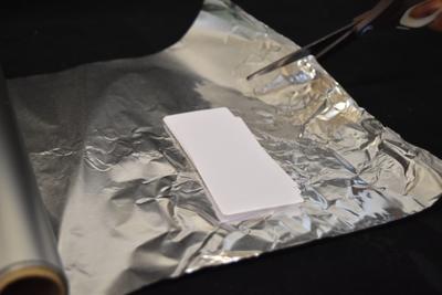
Firstly, cut a piece of aluminum foil significantly bigger than the filling material. |

|
Mark the geometry of your filling material with a marker. |

|
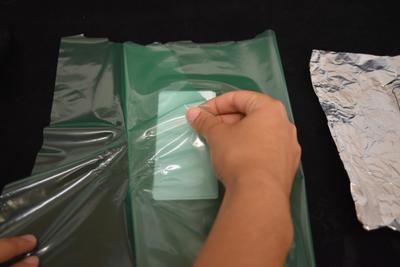
Enclose the filling material between two sheets of TPE. |

|
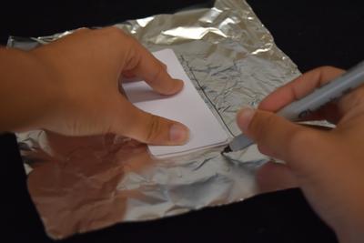
Place the aluminum foil on top of the top layer of TPE and iron the sides of the filling material, being careful to not iron inside the outline. |
|
The temperature of the iron and the time needed to correctly seal the TPE will depend on the iron settings and the type of TPE used. To check if sealing was successful, gently try to separate both layers of TPE after ironing them. If the layers can still be detached, iron the region again for more 5-10 seconds. |

|
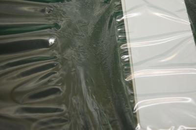
Continue ironing every side of the Laminar Jamming Structure. |
|
After ironing the structure, a sealed strip should be visible in the TPE. Carefully cut extra material and follow the instructions at the Fabrication: Classroom - Impulse Seal and Final Adjustments to connect your tube and prevent leaks from your Laminar Jamming Structure. |
Alternatives to Vacuum Pump
In this page you will find alternatives to applying the vacuum pressure in the Laminar Jamming Structure continuously, instead using portable or simpler ways to create the necessary pressure for jamming. Nevertheless, consider that most alternative devices, as of now, cannot adjust the pressure applied and can lead to performances that are inferior to when the vacuum pressure is applied through industrial vacuum pumps.
Using a Portable Device
|
There are a number of portable vacuum sealing devices that can be used to apply vacuum pressure in your Laminar Jamming Structure. Those can be found in the "kitchen appliances" departments in sites such as Amazon. Here is a list of such devices:
|
DIY Alternatives
Some tutorials for simple alternatives to vacuum pumps are presented below:
|
|
|
|
Case Studies
Tuning the Impact Response of Drones
 This case study describes the design of a Laminar Jamming Structure integrated into drones, here referenced as unmanned aerial vehicles (UAV). The work was carried out by Narang, et al (2018B).
Two-Fingered Grasper
 This case study describes the design of a two-fingered grasper that can perform pinch or wrasp grasps, according to the pressure applied in its Laminar Jamming Structures. The work was carried out by Narang, et al (2018A).
Tuning the Impact Response of Drones
 This case study describes the design of a Laminar Jamming Structure integrated into drones, here referenced as unmanned aerial vehicles (UAV). The work was carried out by Narang et al (2018B).
Objective
To create a tunable device that can modify the impact response of Drones by adjusting the vacuum pressure applied.
Design
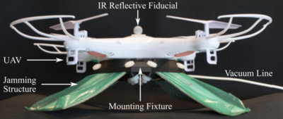
Four twenty-layer 125 mm × 50 mm jamming structures were fabricated. A 3D-printed fixture was designed that cantilevered the jamming structures at 30◦ from the bottom of a UAV, constituting landing gear. The tests were designed to simulate slow and fast landings of a UAV. It was hypothesized that for a given landing velocity, there existed an ideal vacuum pressure for the jamming structures that would simultaneously minimize peak forces on the UAV while also preventing its chassis from bottoming out (i.e., striking the ground). During each test, the vacuum pressure on all four jamming structures was set to the desired level.
|
|
Among the pressure conditions, the 36 kPa condition was ideal, as it exhibited lower peak forces and a higher decay rate. The preceding results demonstrate that jamming structures can also be integrated into traditional rigid robotic systems to rapidly tune impact responses. Furthermore, given their light weight, high damping force range, and effectively infinite damping resolution, jamming structures may constitute a compelling mechanism for active UAV landing gear
Two-Fingered Grasper
 This case study describes the design of a two-fingered grasper that can perform pinch or wrasp grasps, according to the pressure applied in its Laminar Jamming Structures. The work was carried out by Narang, et al (2018A).
Objective
In robotic hands, compliant fingers that bend continuously can facilitate wrap grasps around large objects, whereas rigid fingers that bend discretely at joints can facilitate pinch grasps around smaller objects; it is challenging to design and fabricate hands capable of both. To accomplish the task, we built a two-fingered grasper in which each finger consisted of a cable-actuated variable kinematics system with a rounded fingertip.
Design

|
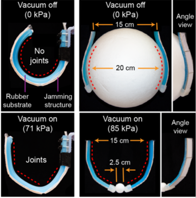
The proposed design is seen in the diagram in the left and is pictured in detail in the right. Three Laminar Jamming Structures are enclosed in an airtight envelope with narrow gaps in betweens them. Each fingertip in the two-fingered grasper has a cylindrical surface with a radius of 5 mm. The fingertips were cast using a two-part mold from PDMS rubber. The airtight envelope is glued to a rubber substrate. A cable is insrted through a channel in the substrate and tied off at the end to a plastic nut. Pulling the cable actuactes the finger.
When no vacuum was applied and the cables were pulled, the device could perform a stable wrap grasp on a ball of diameter 20cm. When vacuum was applied first, the device could perform a stable pinch grasp on a ball of one-eighth the diameter

Design Tool
In this section, we present some of the physical principles that explain the behavior and mechanical properties of Laminar Jamming Structures when jammed and unjammed. We also provide physical equations that can guide design decisions for the fabrication of LJS. Lastly, we provide a design example of a variable-stiffness problem and some relations between structural characteristics and damping ability.
Stiffness Calculation
 By definition, stiffness is the measurement of the resistance to deformation. In a regular 3-point bending test setup as the one shown on the left, stiffness can be calculated by the relation Applied Load / Deflection, as given in the following formula:

where k = stiffness, F = applied load, d = deflection, E = Young's modulus, L = Distance between supports and I = area moment of inertia.
For an unjammed Laminar Jamming Structure, the moment of inertia is calculated considering that each layer is completely independent, whereas, for a jammed LJS, we can consider that the layers are fully coupled.

This difference in moments of inertia leads to a radically different calculation of stiffness for jammed (kj) and unjammed (ko) structures, in which the ratio between the two (which is also known as the range) is n2.


As it can be seen from the image below, the stiffness of the LJS can be also calculated from the slopes of the linear regions in the force-deflection curve.

Yield Point and Critical Force
The yield point for a Laminar Jamming Structure is defined as the point after which any deflection will cause the layers of the structure to slip with respect to one another. Therefore it is proportional to the coefficient of friction between layers. Because the structure slips due to shear, the yield occurs when the shear stress in the structure equals the maximum shear stress (τmax) that can be supported by friction (μP). Note that the maximum shear stress in the rectangular beam is 3V/2A. After yield, the structure becomes much less stiff.


Design LJS for Variable Stiffness
If I load my sample with Fstiff Newtons applied in the center and don't want the structure to deflect more than Dstiff mm in the jammed state, I should pick kj such that:

If I load my sample with Fcompliant Newtons and want it to deflect by at least Dcompliant in the unjammed state, I should pick ko such that:

Make sure your load Fstiff does not exceed Fcritical, as the stiffness decreases after yield, as mentioned earlier.

Please note that these calculations were made with the assumption that the applied load was done under a 3-point bending test. You may use/derive different formulas for different loading conditions.
Design LJS for Variable Damping
Damping corresponds to the amount of energy dissipated by your structure. There is not a simple analytical expression to calculate it according to your structure, but damping should scale linearly with μ, P and n.
If you want to use your Laminar Jamming Structure as an energy dissipation mechanism, make sure that the structure is jammed and that the forces applied are above the yield point.

Testing
In order to evaluate Laminar Jamming Structures, we present some empirical tests that may help you quantify and characterize the performance of the jamming structure.
Bending Test

This test was performed in Narang et al (2018).
In 3-point bending testing done in a universal materials testing device (e.g. Instron), important comparisons between properties of Laminar Jamming Structures when vacuum is on or off can be drawn. The structures were placed on the fixture according to the setup (left image) and loaded until a maximum displacement was achieved. Force and displacement measurements were simultaneously recorded.
The mechanical behavior of LJS can be summarized by the image in the right. When vacuum is off, the structure has low bending stiffness, which is proportional to the slope of the curves. When vacuum is on, the structure has three deformation regimes. In pre-slip, the bending stiffness is maximal and constant. After the first critical load, the structure enters the transition regime, in which the layers begin to slip and the bending stiffness decreases. Note that the first critical load corresponds to the yield point. After the second critical load, the structure enters full-slip, in which the layers have slipped at all possible points along their interfaces. The bending stiffness is minimal and constant. When slip occurs, energy is dissipated to friction between the layers, and the structure behaves plastically.

In the experiment above, the effect of the number of layers and of vacuum pressure on the mechanical behavior of the LJS is also displayed, illustrating the different ways in which properties such as stiffness and maximum yield can be tuned.
The 3-point bending test can also be replicated in a classroom setting with calibration weights, for purposes of qualitatively assessing the changes in LJS's stiffness in a simple way. In the video below, you can see a demonstration of this easily replicable test.
|
|