Shape Memory Alloy Driven Whole Skin Locomotion
Description
We intend to experimentally examine the feasibility of whole skin locomotion (WSL) through the posterior contraction of an elongated fluid filled torus (FFT). Whole skin locomotion “works by way of an elongated toroid, which turns itself inside out in a single continuous motion, effectively generating the overall motion of the cytoplasmic streaming ectoplasmic tube in amoebae.”[1] In WSL, the entire exterior of the torus moves in the same direction. This is a significant because it allows any surface the torus comes into contact with, top, bottom, or side, to be used to propel the torus forward. 
This project was performed by Junwon Lee, Cameron Wierzbanowski, and Harrison Young. We are all students at Franklin W. Olin College of Engineering.
Criteria For Success
Our goal is to develop a prototype of a WSL driving mechanism that uses shape memory alloy (SMA) contractile rings to invert an FFT. While the feasibility of such SMA mechanisms have been examined using finite element analysis [9], we are not aware of any functional prototypes. We hope the success of this project will ignite greater interest in WSL platforms among the academic community.
We hope to produce a proof-of-concept prototype capable of reliably rolling forward. The team will also evaluate the speed and power consumption of the drive system. These metrics will be used to identify potential improvements and prototype feasibility.
Background
One of the most exciting applications of soft robotics is the creation of flexible locomotive robots. With their compliant nature, these robots could be ideal for traversing the constrictive and unpredictable terrain commonly found during search-and-rescue situations. For years, researchers have aspired to design locomotive systems viable for this purpose. WSL has attributes that suggest it could excel in this arena; however, our team feels it has been under-investigated by the academic community.
WSL is inspired by the movement of an amoeba, whose locomotion heavily depends on pseudopods and cytoplasmic streaming. In this process, endoplasm flows into developing pseudopods causing them to grow away from the cell body. At the same time rear facing pseudopods are retracted into the cell. This motion allows these microorganisms to move effectively through their environment. In WSL, an inverting torus is often used to mimic the effects of cytoplasmic streaming. [1] As the torus inverts, the entire exterior facing membrane moves in the same direction and returns though the center.
|
|
WSL has several advantages compared to other popular locomotive mechanisms such as two-anchor and wheeled locomotion. In two-anchor locomotion, a robot uses anisotropic friction to move forward by extending and contracting its body. In this system, the forward pushing ability is limited by the difference in the coefficient of friction in the forward and backward directions. [2] This limits their efficiency in restricted environments. Wheeled locomotion faces a similar limitation in that the friction force on the bottom half of the wheel has to be larger than the force on the top half. Most wheeled solutions simply prevent the top half from contacting the environment altogether, as a result this solution has limited utility in highly confined spaces. WSL does not face such limitations; any surface, top, bottom, or sides, can be used for forward movement. This property would give the robot a lot of potential for uses in the emergency response and medical fields; it would be well suited for traversing tight spaces such as those found in collapsed buildings or the human gastrointestinal tract. [1]
Several robots have been developed to explore the applications and viability of WSL. (A) Shows an FFT filled with faro-fluid that can be manipulated using magnetic fields. [4] In (B) an FFT was successfully driven using ionic polymer-metal composites (IPMC). [5] (C) Shows an early prototype of an SMA actuated torus. [1] While most WSL robots can be classified as soft, traditional WSL robots have been developed. (D) Shows a snake-like robot utilizing WSL actuated by traditional DC motors. [6]
Design
 |
Design Process
Our design uses thermally activated SMA contractile rings to invert an FFT. By contracting the rings on either end, we are able to achieve WSL through inversion of the torus.
The prototype was designed in three steps. First, we identified an appropriate toroidal membrane to support the drive system. Then, we designed brackets compatible with the membrane and quantitatively measured the required force necessary to invert the torus. Next, we designed SMA coil actuators to meet these specifications and assembled the completed prototype.
Strengths
SMA actuators must cool to a baseline temperature prior to activation. Therefore, cycle time is dependent upon the actuator cooling rate. Our system reduces cycle time through environmental manipulation. Following activation, the contractile rings move to the center of the FFT where they are surrounded by a water filled membrane effectively acting as a heatsink. Additionally, each ring is activated exactly once per toroidal revolution. The combination of a passive heat sink along with infrequent activations of individual contractile rings theoretically gives WSL systems a high speed cap.
Weaknesses
By nature, SMA actuators require significant power. They are heat driven and actuated by running electric current through the actuator wire. This process is approximately 3-5% efficient at converting electrical energy to work (for comparison DC motors can be up to 90% efficient). The final prototype required 3.7 watts of power.
The chosen membrane was not completely compatible with the drive system. The contractile rings occasionally melted through the membrane; the resulting leak was irreparable, requiring fabrication of a new device. As a precaution, our team only heated actuators for fractions of a second, minimizing the potential for damage.
Toroidal Membrane
Membrane Criteria
 |
The toroidal membrane is the primary structure and source of friction of the drive system. This component was determined first because the design of both the brackets and contractile rings are affected by the properties of the chosen membrane. Four qualities were considered during membrane selection: rolling resistance, heat resistance, ease of manufacture, and ease of adhesion. Qualities were rated on a scale of 0-3 where 0 is unusable and 3 is exceptional. Three toroidal membrane materials were evaluated: Ecoflex 00-30, low density polyethylene (LDPE), and vinyl. The Ecoflex and LDPE membranes were fabricated in-house and the vinyl FFTs were purchased online under the product name “Water Wigglies”.
Membrane Evaluation
|
Ecoflex 00-30 |
LDPE |
Vinyl (Water Wigglies) |
|
|---|---|---|---|
|
Heat Resistance |
3 |
0 |
2 |
|
Roll Resistance |
1 |
3 |
2 |
|
Ease of Manufacture |
1 |
2 |
3 |
|
Ease of Adhesion |
1-3 |
0 |
3 |
|
Total |
6 |
5 |
10 |
Ecoflex 00-30: The Ecoflex toroidal membrane was fabricated by inverting a long thin-walled tube onto itself. While this membrane had superior heat resistance, it proved difficult to manufacture and invert. Furthermore, Ecoflex bonds well to itself and other silicon rubbers, but is difficult to bond to other materials. This would have resulted in additional design constraints on the brackets.
LDPE: The LDPE toroidal membrane was fabricated using thermally bonded film. This membrane had the lowest rolling friction of the materials tested; however, the SMA actuators melted through it almost instantly. This fact alone was enough to invalidate LDPE as a viable membrane material.
Vinyl: Vinyl FFTs are commercially available on Amazon.com and are reasonably invertible toroidal membranes. Like LDPE membranes, vinyl can be melted by the SMA actuators. However, these actuators melted in minutes rather than seconds. This was deemed acceptable for prototyping purposes. Rolling friction was significantly reduced by lubricating the FFT with dishwashing soap.
Future Work
Vinyl FFTs are the best of the three membranes evaluated; however, the melting problem proved significantly more detrimental than anticipated. Future designs will focus on the development and implementation of non-thermoplastic membranes. Currently, the viability of the Ecoflex membrane is being reinvestigated. The low scores in “ease of manufacturing” and “rolling friction” are potentially a result of the manufacturing process used to fabricate the membrane and not the material properties of the rubber.
Brackets
Geometry
The brackets make it possible to connect the SMA contractile rings to the drive system without gluing the wires directly to the membrane. This fabrication method allows actuators to be reused or transferred between prototypes with minimal risk of damage. Additionally, the use of brackets provides more control over the interaction between the actuators and the membrane.
Our team hypothesized longer brackets would be more efficient at inverting the torus. It was assumed the long arm of the bracket would act as a second class lever, pushing the torus inward. Brackets were designed with and without the lever arm.
 |
Brackets without the lever arm are referred to as point brackets. Brackets with the lever are referred to as double brackets. The length of a double bracket is considered to be its center distance. Three brackets were tested, point brackets, as well as two lengths of double brackets, 0.25" and 0.375". All brackets were fabricated using an FDM 3D printer. |
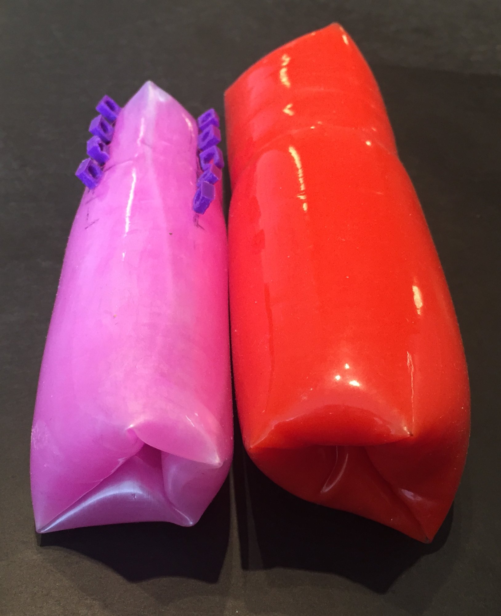 |
In addition to bracket geometry, two brands of FFT were tested. These FFTs had 125mm and 110mm circumferences. |
Experiment
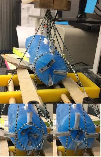 |
An experiment was designed to quantitatively assess the contractile force needed to invert the vinyl toroidal membranes and determine whether this force was affected by bracket geometry. A drawstring-bag-like pulley system was used to simulate contractile force. The force and extension was measured using an instron material tester. In each test, vinyl FFTs were contracted about 45%. Forces were averaged over three tests. |
Results
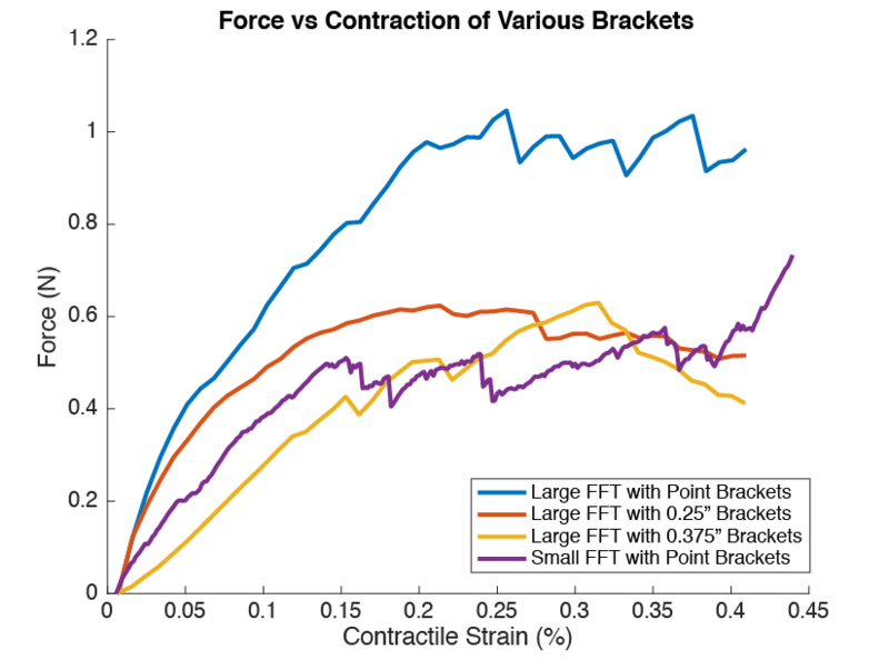
Results of the experiment do support the hypothesis that longer brackets invert the torus more effectively. However, despite the apparent correlation, the point brackets on the smaller torus required approximately the same force as the long brackets on the larger torus. This suggests the smaller torus is easier to invert overall. We were unable to evaluate the effect of double brackets on the small torus because of difficulties with membrane adhesion.
Final Bracket Design
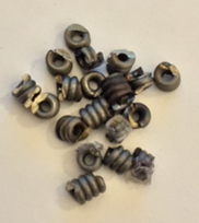 |
Both membrane sizes could be inverted using similar amounts of force. However, the larger membrane required the use of double brackets. These were fabricated using a 3D printer and often melted during testing. As a result, they were deemed unsuitable for the prototype. Point brackets were fabricated from thin coils of spring wire. This bracket was impervious to the heat generated by the SMA actuator and selected for the prototype. |
Minimum Force
To establish the minimum force required to invert the torus, a vinyl FFT was lubricated and inverted using progressively weaker actuators. It was determined the required force to reliably invert the torus is 0.3N.
Future Work
Development of SMA compatible double brackets is being investigated. Possible manufacturing processes include SLS 3D printing and resin casting.
Coil Actuators
Nitinol
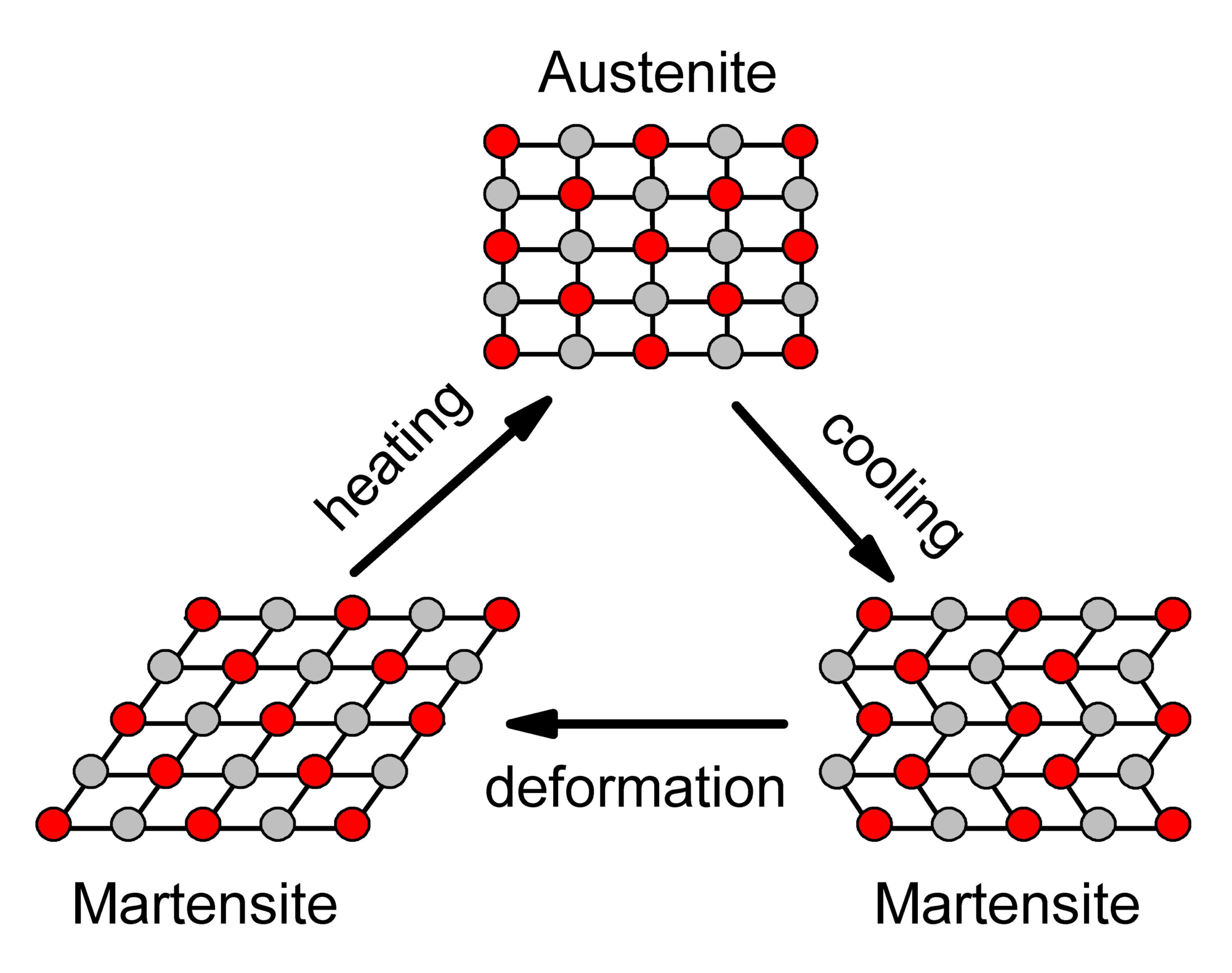 |
The contractile rings are composed of coils of Nitinol (NiTi) wire. NiTi is a nickel titanium alloy that changes shape when heated. It accomplishes this though phase transition between austenite and martensite. In austenite, NiTi has an organised crystal structure where nickel and titanium atoms are held tightly in place. In martensite, the atoms are more loosely held than austenite and the structure is able to deform slightly without breaking any atomic bonds. When deformed martensite is heated it transitions into austenite. As the atoms reform into austenite the NiTi returns to its original shape. |
The original shape can become stabilized through a process called shape setting. In shape setting, the NiTi is fixed in a deformed state and annealed to reset the structure of the austenite. The contractile rings were annealed at 390 degrees C for 20 minutes. [7]
Coil Actuators
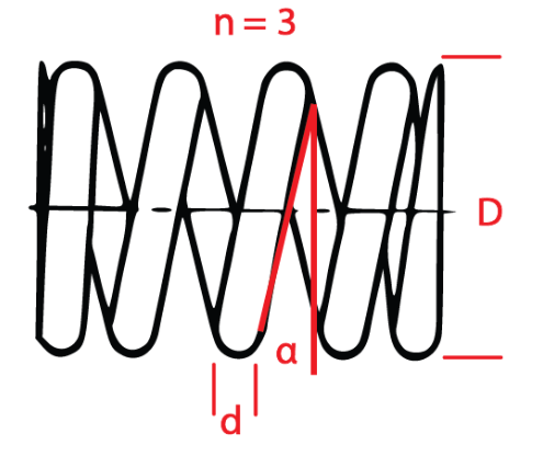 |
NiTi can only recover from about 6% strain. In straight NiTi wire the stroke length is equivalent to strain; however, in a helical wire, the relationship between stroke length and strain is nonlinear. In helical wire, stroke lengths of 200% to 1600% can be achieved while deforming the wire 6%. The stroke length and strength of the coil actuator is largely dependent on four parameters: diameter of actuator wire (d), diameter of coil (D), initial pitch angle (⍺), and number of active coils (n). [8] There are caveats when designing SMA coil actuators. Stroke length of an actuator is typically inversely related to its strength. [8] Additionally, NiTi actuators are monodirectional and require an external bias force to be reset following actuation. SMA coil actuators need enough strength to overcome bias force in addition to the strength needed to perform the desired task. The net force is the force available to perform work. |
Designing The Actuator
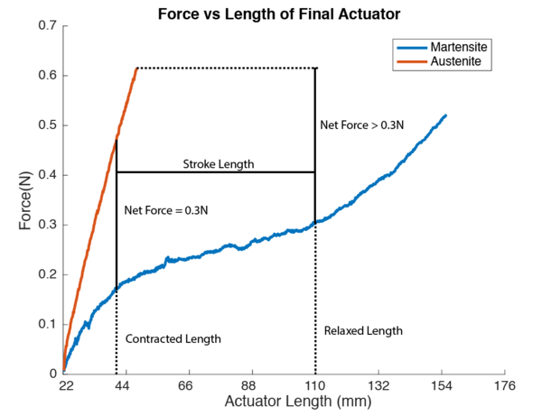
The contractile ring is simply a coil actuator bent in a circle. Through observations of the FFT it was determined the relaxed ring actuator should have a circumference of 110mm and contract down to 30mm. The ring must also be capable of maintaining a net contractile force of 0.3N throughout actuation.
The Actuators
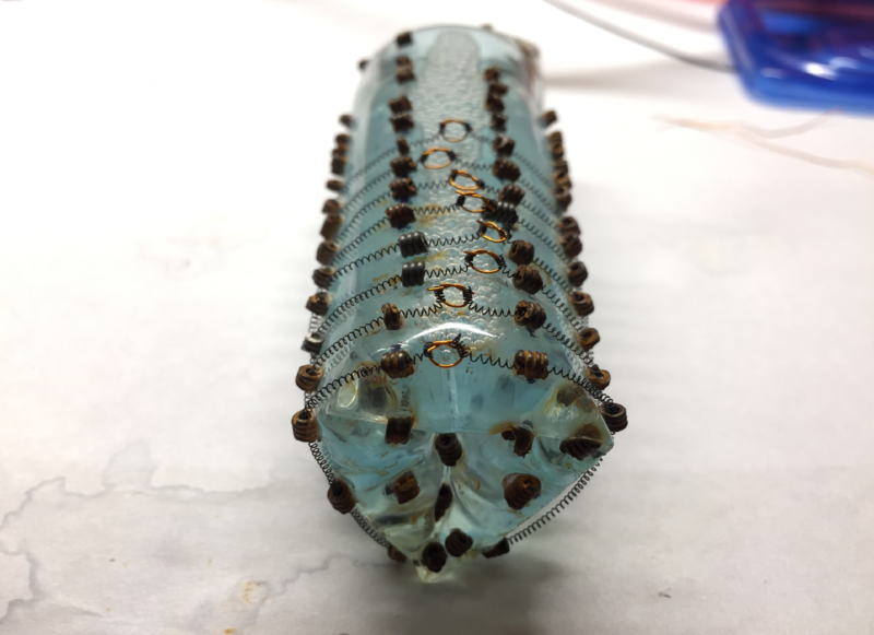
The acutaor ring will contract until the net force falls below the 0.3N needed to invert the FFT. Through some trial and error we were able to design a coil actuator that roughly met all of the requirements outlined in the section above. The final actuator design has an actuation strength 0.62N and requires 0.28N to deform to a length of 110mm. Actuators were fabricated out of 0.15mm NiTi and had a coil diamiter of 0.9mm. They have an initial length of 22mm and can elongate to 110mm while experiencing 4% strain. The contractile ring is made by connecting both ends of the actuator to a loop of magnet wire. The magnet wire allows the two ends to be held together without shorting.
Electrical
The contractile rings are actuated by 20 volts from a regulated DC power supply. NiTi is extremely difficult to solder. Therefore, power cables were connected mechanically to the contractile rings though the metal brackets. Each ring is powered by an individual mosfet and the entire prototype is controlled using an external Arduino Mega 2560.
 |
Future Work
Currently, the prototype relies on the inversion of the torus to re-expand the contractile rings on the front of the drive system. This strategy is unreliable. The team is currently working to develop contractile rings that passively expand when not activated.
Fabrication
Fabrication is divided into three sections: Membrane, Coil Actuators and Brackets, and Assembly.
Membrane: Instructions to prepare the pre-purchased vinyl membrane for fabrication.
Coil Actuators and Brackets: Instructions for fabricating contractile ring actuators and point brackets from stock wires.
Assembly: Assembling the WSL Drive System from fabricated parts.
A zip folder containing all files and the bill of materials can be found below.
Contents of Zip Folder
- SMAWSL_Template: Template for backet placement
- Spring Maker: STL of piece used in coil fabrication
- WSLBOM: Project BOM
| smawsl.zip | 59 KB |
Membrane
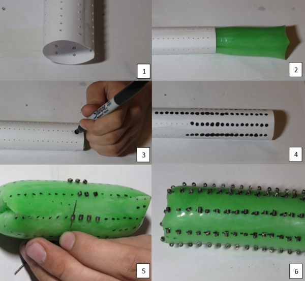
When Water Wigglies are shipped, the outer layer is slightly stretched. This makes them favor one position when inverting. To adjust for this, role the torus inside out and store for a few days. This evens out the membrane and makes it suitable for use.
Lubrication
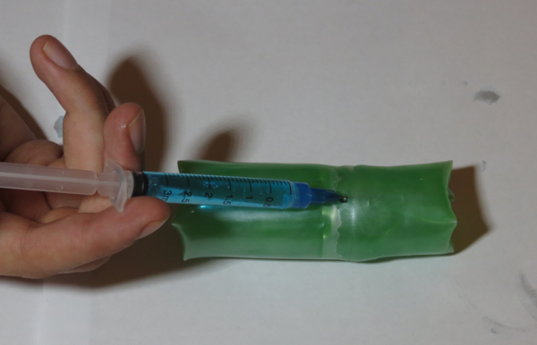 |
Clean factory oil lubricant off the FFT. Slowly inject 10-12ml of dishwashing soap using an adhesive syringe. Do not roll or shake the FFT! If the water and soap mix, it will be difficult to glue the injection site closed. |
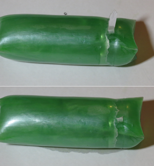 |
Make a patch by dipping a piece of printer paper in cyanoacrylate glue. Remove the needle and quickly apply the patch.
If the patch does not leak, lightly shake the FFT to mix the water and soap.
|
Do not try to patch a torus that is leaking soapy water. Torus should be drained and rinsed before attempting any repairs.
The torus is easier to repair when empty. If you can not close an injection site, empty the torus, close the hole, and try again at a different location.
Coil Actuators and Brackets
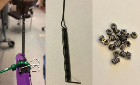
NiTi Coil Actuators
An NiTi coil actuator is fabricated by wrapping a strand of thin NiTi wire around a shaft and setting its shape. Each 22mm coil uses about 34cm of straight wire. A single 5m spool has enough wire to make 10-12 actuators.
 |
|
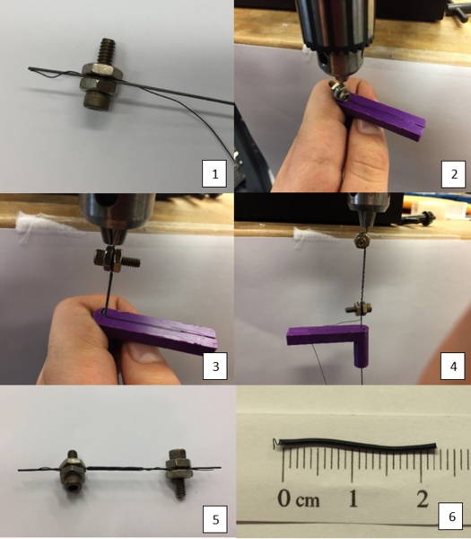
Point Brackets
| Music wire is considerably stiffer than the NiTi wire and therefore must be secured more firmly. To create the point brackets, use steps 2-4 above, using 0.029" music wire in place of the NiTi and a 0.042" core. Keep fingers away from the winding coil. If released, the remaining wire can whip around and cause injury. After the spring is compete, cut every three coils using a dremel. Do not cut the wire with pliers. This will cause burrs that can puncture the FFT membrane. |
|
 |
.
Assembly
Attach Brackets
 |
|
Make Contractile Rings
 |
|
Wiring
 |
-
Take a length of magnet wire roughly 3X torus length and sand off the enamel.
-
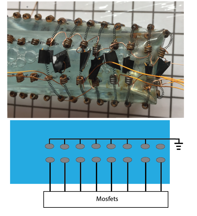
Choose a column of brackets alongside the magnet wire knots. Thread the sanded wire through the full column of brackets, making sure the wire contacts the actuator wire in each one. This will be the common ground.
-
Take a length of magnet wire roughly 3X torus length and sand the enamel off roughly 0.25" - 0.5" off the ends. Repeat with wires for as many actuators as you intend to mobilize.
-
Connect these wires to the brackets on the opposing side of the knot, ensuring each is individually connected.
-
Connect all free ends of these wires to mosfets, one mosfet per actuator.
-
Supply the mosfets with 20 volts from a regulated DC power supply.
|
|
Testing
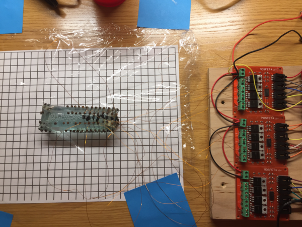
Each square is one cm in length. In 9 seconds the drive system was able to travel roughly 35mm. This equates to an average speed of approximately 3.9mm/s. The contractile rings were teleoperated and activated by pressing a pushbutton. The device runs on short bursts (6.3 ms) of 20 volts and draws 1200 mA of current. Power consumption was estimated during testing by counting the number of video frames the contractile rings were activated (determined by the red LED on the mosfet). Throughout the test the contractile rings were activated 22 times for a total of 1.39 seconds throughout the test. From this we estimate the device consumed an average of 3.7 Watts over the course of the test.
Conclusion
Our prototype met both our goal and objective. It successfully provided a proof-of-concept prototype for a WSL driving mechanism using SMA contractile rings to invert an elongated FFT through posterior contractions. The device moved forward reliably.
We would like to start exploring the practicality of an untethered WSL prototype. In preparation for this task, future work will focus on expanding the contractile rings on the front-end of the torus, as well as reducing the overall power consumption of the system.