The King Actuator - Instruction Through Actuation
An Exploration into Modular, Continuous-Pour Soft Robotic Actuators with Soluble Inserts for Improved Actuation
One of the goals of soft robotics is to simplify and increase the efficiency of the actuator fabrication process. Traditionally, a two part mold has been used to create simple soft robotic actuators. In order to increase the durability of the actuator, we set out to design a new, single-mold system made from common household materials. Our Soft Robotics Team decided to try and develop molds and methods that would result in stronger actuators and easier development. Students and hobbyists are gaining interest in soft robotics, so we wanted to increase the access to high-quality actuators by simplifying the fabrication process. We believe that using soluble inserts and a continuous-pour mold allows for actuators to be produced with less expensive and more readily available materials. Additionally, we believe that this single pour method will eliminate the reoccurring problem of delamination, a drawback of the two-part molding system.
Soft Robotics has a place in the lab, manufacturing facilities, and at the kitchen table. As an application for our new actuators, we specifically looked into the use of soft robotics in the ceramics classroom. In tandem to our exploration with continuous-pour actuators with soluble inserts, we collaborated with our art teacher and attempted to manufacture a soft robotics glove able to help teach novice artists how to throw a clay pot.
In our research, we proceeded to:
1. Conduct background analysis on PneuNet actuators
2. Design a manufacturing process for continuous-pour actuators using dissolvable inserts
3. Fabricate and test the King Actuator (The name "King" comes from Edward King, who conceptualized the idea)
4. Design, fabricate, and test a pressure-sensing glove for use inside of the ceramics classroom
Use the buttons below to navigate to the individual sections of our project:


The following infographic gives a general overview of our design process this year:


Background
While working on last year’s project, we noticed issues regarding the delamination of actuators that occurred while using the two-part mold. The delamination caused our edible actuators to have a relatively low success rate, as even the slightest amount of air sheared the air cavities from the base. This made the actuators unsuitable for rigorous actuation and multiple actuation cycles.
Evident from our project last year, we are passionate about increasing the accessibility to soft robotics. It allows for more students to have their interests in material science and engineering piqued the same way soft robotics piqued our interests in those fields. To increase accessibility, we set out to design an actuator that could be produced with ease. We hypothesized that the use of a soluble internal structure could be used to create the air chambers for inflation, making the fabrication process simpler. Our team believes that this process of fabrication has never been done before.
Our mentor implemented soft robotics into the engineering curriculum at our school. One of her students, Ed King, was building the Soft Gripper from the Resources for Educators when he too struggled with the delamination of the actuator. He then had an idea: rather than using a two-step process and have the structural integrity rely on the layers weakly fusing together, why not use a single mold to create the entire actuator in one go? The key to his new method, dissolvable inserts, would allow him to use a single mold to create actuators. No lamination required.
He decided to cast silicone around a polystyrene (styrofoam) insert and dissolve it using acetone after the cast has cured. This idea of soluble actuator inserts marked the beginning of the King Actuator.


Figures 1, 2, and 3: Initial design sketches, first prototype, and first successful actuation
The images above show the conceptualization, the fabrication, and the actuation of one of Ed's first King Actuators. The difference in density of the silicone and styrofoam materials caused the styrofoam to float. While we were excited about Ed's innovation, we knew there were was room to improve, and thus, our iterative design process began.
At the same time, the ceramics teacher at our school, Mr. Raeder, approached us with a problem: he wanted a more effective method of teaching his students how to throw a pot. He described the difficulty of instructing complex, nuanced motions to his students. Mr. Raeder told us, "If a student’s relaxed hands could feel pressure to move the correct way using soft robotics, it would be very efficient and convenient.” We believe that using a glove similar to that described in Polygerinos et al. (2013) would be ideal in aiding a student's learning in ceramics and reduce the time necessary to become proficient in the art.

Figure 4: Mr. Raeder teaches a new student how to throw a clay pot
Our goal for the 2018 Soft Robotics Toolkit Competition was to create a single-pour actuator manufacturing process using a dissolvable insert in order to prevent delamination and increase actuator durability. From the start of our research, we defined our success as creating an easy-to-make and durable actuator design. In tandem to our project, we would like to develop the foundations for the teaching of ceramics through soft robotics. While our project is not centered around teaching ceramics, we believe that soft robotics has a place in teaching anything that requires muscle memory or complex, nuanced motions, and would like to make progress in that field with this new application.

Figure 5: A King Actuator prior to the polystyrene insert being dissolved.
Design
Preliminary Actuator Design
While creating silicone-based actuators using the PnueNets, we encountered issues when attempting to seal the two portions of the mold. Due to the two parts of silicone curing separately, the seal between the bottom layer and the actuator itself was not completely air-tight, resulting in its delamination. In consideration for a simpler process and reliable actuator, we noted features we would like to have for an ideal actuator.
A continuous-pour mold was one of our priorities, as such a process would reduce the time required to fabricate an actuator and eliminate the issue of delamination. However, this brought the challenge of forming the actuator's insert structure, which needed to be removed from the mold in a single motion.
Edward King, a student at our school, conceptualized a system where the inserts inside the mold could be dissolved, creating an air pocket for actuation. King considered using materials such as polystyrene (styrofoam) for such a process. Another benefit we considered in our design of the insert-dissolving method was that the air pockets could now have more complex geometries. A two piece mold limits one’s air pockets to the shape of a rectangular prism. Different geometries such as circles, trapezoids, and parallelograms would now be possible.
Once we formulated the first design and a potential application to test the actuators, a styrofoam insert was manually cut and fit to a simple rectangular mold. We poured a different, transparent material, polydimethylsiloxane (PDMS), into the test cardboard mold so we could physically view the dissolving process. Upon first glance, the large deviation between the densities of each material caused the styrofoam to rotate and float upwards, rendering the actuator unusable in practice. However, as expected, the dissolving of the insert using acetone through a manually poked hole was quick and simple.

Figure 6: Polystyrene insert in clear PDMS mold
Another observation we made was that the manually poked hole (created previously using a Wilton brand cookie flooding etching tool) should, ideally, be built into the mold. This would be done to create consistency from actuator to actuator, to aid in airflow during actuation, and to help dissolve the Insert. After the first test, we considered using fabric on one end of the mold as an inextensible layer to help constrict that side, reducing the overall vertical volume of the actuator. After we finished the simple prototype to gain preliminary information about the style of actuator, we began our iteration on the first version.
Actuator Design Iteration and Fabrication
Version 1:
Once we realized the amount of precision needed when creating these actuators, we switched to using 3D-Printed PLA (polylactic acid) for the base molds, and PVA (polyvinyl alcohol) for the inserts. PVA is water soluble which ideal because a soluble insert allows us to utilize a one-pour process. We can remove the PVA using water after the silicone is cured, leaving the connected air chambers which allow for the inflation and bending of the actuators. Using PLA, we could mark each iteration of mold dimensions with color-coding printer filament. Also, another incentive for using PVA was to test a different material than stryofoam, as our tests with stryofoam were successful. These materials are easy to manipulate as we could 3D-print them and easily change their dimensions. We also transitioned to using EcoFlex™ 00-50 Two-Part Silicone for the actuator structure.
(See the Bill of Materials for more detailed information regarding the materials we used)

Figures 7, 8, and 9: 3D printed molds, a 3D printed insert, and completed V1 actuators
Dimensions:
- Orange Mold: 16.70 x 105.60 x 15.88 mm
- PVA Insert: 12.70 x 88.90 x 9.53 mm
Fabrication Process for First Iteration:
-
Lay down a single layer of fabric
-
Pour the mixed silicone halfway up the depth of the base mold
-
Place the insert centered in the mold
-
Fill rest of the mold with silicone
-
Wait for the mold to cure
-
Remove by pulling up the sides by hand
-
Dissolve the insert
In contrast to the styrofoam inserts, the PVA roughly maintained its position relative to the mold and did not float at all. Another key observation we made was about the dissolving process of the PVA. Before using the compound we tested the water solubility of the PVA in an experiment. Although it was apparent the material required an extensive amount of time to dissolve, the data was not representative of the actual dissolving process inside an actuator. First, it was difficult to expose the entirety of the PVA insert to the heated water through a minuscule hole. In doing so we tore the side walls of the actuator from inserting the nose of the pipet and creating pressure with water.
Version 2:
In the next iteration, we focused on changing the dimensions so there was less height and more width. The extra width added material to the sides so the actuator would not tear, and we compensated for less overall height with more layers of fabric. We also decided to switch back to the polystyrene inserts as they with our current methods could dissolve. However, still challenged with the floating issue of the styrofoam, we noted the inserts and constricting fabric could vertically swap their position such that, if the inserts floated upwards, they would only move towards the side with the fabric.

Figure 10: Swapping the position of the fabric and inserts
Dimensions:
- Yellow Mold: 23.05 x 105.80 x 12.70 mm
- PVA Insert: 12.70 x 88.90 x 3.18 mm
Fabrication Process for Second Iteration:
-
Fill the mold with mixed silicone
-
Lay two layers of fabric on top
-
Attach strips of velcro
-
Wait for the silicone to cure
-
Dissolve
Version 3:
As we were brainstorming various designs for an actuator to assist one's motion, we decided to use strips of velcro to allow the actuator to be attached to a finger. This would be more versatile than a glove as the as there is no limitation on the user’s hand size.


Figures 11 and 12: Attaching velcro to a mold and velcro attachment testing
(Note: We tested the velcro technique using a PnueNet base in the image above)
Althought the previous actuator iteration was generally successful as it could actuate multiple times, assited in applying force when worn, and did not tear or break while doing so, there were still a few issues. The dissolution hole still had to be manually made, which is counter-intuitive to the goal of simplicity, and makes the dissolving process more tedious. The actuators also, comprising of simply a block with an air channel, had difficulty inflating and bending in the same motion as the PneuNet actuators. What our actuator lacked, which most soft actuators have, are incisions, or slits, to help increase the range of motion. In our case, our actuators had a wide range of motion, but at the cost of the stretching of the silicone. Each air pocket, when inflated, looked and behaved similarly to the inflation of a balloon. The material did not rip due to our solution's elasticity, yet the long-term reliability was questionable. This led us to a design that utilized sectioned air pockets and attachable inserts that could be anchored by the mold.

Figure 13: 3D models of the final mold and insert
In between the iterations one series of the 3D printed mold suffered from scaling issues where the size of the parts did not match, one series lacked the vertical indents, and one packed the air pockets too closely.

Figures 14, 15, and 16: a 3D printed mold and claws, a fabrication error, and a completed actuator
Of the final generation, we could only completely remove the PVA insert of one the molds through a painstaking process. We decided that if we were to continue, and use the actuator for applications like a motion assisted glove, we should test casting inserts into a mold, and then dissolving said inserts.
Dimensions:
- Slot Mold: 25.40 x 123.83 x 15.88 mm
By the nature of us 3D printing the inserts, we can print inserts that are different shapes and mess with the geometry that way, giving it its modularity. We created actuators using these new geometries, as described in the testing section, but found little difference in actuation.
You can download CAD files for these uniquely shaped inserts here.
Fluidic Control Board and Sensor Glove
Fluidic Control Board Design
We used the fluidic control board instructions with some modifications, as our end application projection required variable PSI output based on information we collected. We controlled the PSI through independent pressure regulators rather than using PWM to have a pressure applied and the end of each fingertip. In addition, we added an LCD to help debug code. As for recording data we tried both Flex and Force sensors, ultimately choosing Force Sensors because we did not care about how much the finger bent, but rather how much force is being applied to the pot.

Figure 17: The schematics and circuit diagram of the fluidic control board
Pressure Sensing Glove Iteration
Using the Pressure Sensing Glove we were able to record the hand motions of an articulate ceramicist. Through trial and error, we created a glove that housed the sensor cable robustly such that it would not interfere with data collection. Originally, we used a Flex sensor hot glued on a latex glove. The glue’s bond was poor and broke near instantly. After switching to the Force Sensor we electrical taped the sensor and extension on the exterior of the glove. Worried that contact between the clay and any electrical components could end up being messy and damage the hardware, we resorted to finally stitching all the components to the interior of the glove. In this manner, all components were hidden and we followed through recording our data.
 Figures 18, 19, and 20: The pressure sensing glove, the sewn on force sensor, and a student testing the sensors
Fabrication
The Bill of Materials for this project can be found here.
Note: For both processes, either polystyrene (PS) or polyvinyl alcohol (PVA) inserts can be used. Here are links to the CAD files for the Original King Actuator and the Continuous-Pour Actuator. To view short time-lapses of the 3D-printing process, click this link.
Additionally, CAD files can be located both through the hyperlinks throughout the fabrication instructions, as well as attached at the end of the page.
King Actuator (Original)
Step (1) - 3D Print the Mold and Insert
3D-Print out the Base Mold provided using PLA. If you choose to use a dissolvable Insert, 3D-Print the provided Insert using PVA. Alternatively, you can use a craft knife to cut the shape of the insert out of polystyrene foam.

Figure 21: A 3D printed mold and a hand-cut polystyrene insert
Step (2) - Mix your Silicone
Use your scale to measure equal masses of your two-part silicone mixture in separate cups. Combine the two parts in another cup and mix for several minutes to help remove some of the air bubbles. On its own, the silicone will start to harden in about 10 minutes, so only mix as much as you will use.


Figures 22, 23, 24, and 25: Pouring out the two parts, adding part A, adding part B, and mixing the two together
Step (3) - Cut out the Fabric Inextensible Layers
Using a craft knife, cut out two rectangular sheets of fabric to the size of the outer mold. Set these aside until all of the silicone has been poured.

Figure 26: A craft knife, a mold, and two sheets of fabric cut to size
Step (4) - Pour the First Layer of Silicone
Pour out a thin layer of silicone into the bottom of the Base Mold. Stop once it reaches a depth of about ½ cm.

Figure 27: Pouring a thing layer of the silicone mixture into the mold
Step (5) - Place the Insert
Place the Insert (either PVA or polystyrene) on top of the layer of silicone. Make sure that it is not touching the walls of the Base Mold and that it does not sit higher than the mold walls.

Figure 28: Carefully laying the insert into the layer of silicone
Step (6) - Fill the Base Mold
Once the Insert is properly positioned, continue pouring the silicone until it reaches just under the rim of the Base Mold. Be careful not to overpour, as things get messy pretty quickly!


Figures 29 and 30: Filling the the mold up with silicone and slowly topping the mold off
Step (7) - Place the Fabric Inextensible Layers
Place the two layers of fabric on top of the filled silicone mold. Be sure that the fabric is centered on the mold and completely saturated with silicone. Placing the fabric down improperly could lead to inconsistencies in performance once the actuator has set.


Figures 31 and 32: Placing a layer of fabric on top of the silicone and adding a second layer to the top
Step (8) - Pour the Final Layer of Silicone and Wait
Pour a final layer of silicone on top of the fabric to ensure that it is embedded into the actuator. Failing to do this will cause the fabric, and eventually the actuator, to tear.
Wait for about two (2) hours for the silicone to set.


Figures 33, 34, and 35: The mold with all its components, smoothing out and saturating the fabric, and waiting for the silicone to set
Step (9) - Actuator Removal
Once the silicone has completely set, remove the actuator from the mold by pulling on its sides. This may require some force. Do not worry if you snap the Insert inside the actuator, as it will be dissolved momentarily. Poke a hole reaching to the depth of the Insert into the end of the actuator. This hole will act as the passage through which the Insert will be dissolved and the valve into which the pneumatic tubing will be inserted.


Figures 36 and 37: A solidified actuator in a mold and the actuator removed from the mold
Step (10) - Dissolution
If you made your actuator using a PS insert, heat up a beaker of water on a hot plate to about 200 degrees Celsius. Place your actuator inside the water and wait for it to heat up. Use a pipette to help funnel hot water into the actuator and dissolve the PS.
If you made your actuator using a polystyrene insert, use a pipette to inject small amounts of acetone at a time into the actuator. Periodically rinse the actuator with water to prevent a build-up of liquified polystyrene.


Figures 38 and 39: Preparing the insert for dissolution, the acetone dissolving the polystyrene, and the liquified polystyrene being flushed out of the actuator
Step (11) - Cleaning and Completion
Rinse out the inside of the actuator with water to remove any excess material that may have been left behind. Once your actuator is dry and clean, it is ready for testing!
King Actuator (Continuous-Pour)
Repeat the Preparatory Steps (1) - (3) of the Original King Actuator, but instead using the Continuous-Pour Base Mold and Insert.
Step (4) - Prepare your Insert
Put the Insert into the claw and slot it into the Base Mold. Be sure that the Insert is straight and parallel to the walls of the Base.

Step (5) - Pour the Silicone and place the Inextensible Layer
Pour the silicone up to the brim of the Base Mold. Then place the fabric inextensible layers, and pour another thin layer of silicone. Wait about two (2) hours for the silicone to set.


Figures 40, 41, and 42: Filling a mold with silicone, layering sheets fabric on top of the mold, and allowing the silicone to set
Step (6) - Remove the Actuator
Once the silicone has set completely, pull the actuator out of the base mold. The claw should become separated from the actuator, leaving behind a rectangular valve.


Figures 43 and 44: Two cured actuators and the actuators removed from their molds
Step (7) - Dissolution
Heat up a beaker of water on a hot plate to approximately 200 degrees Celsius. Place the actuator into the beaker into the water and wait for it to heat up. The valve on the end of the actuator provides an easy passage through which hot water can travel. You can use a pipette to expedite the dissolution process by carefully injecting small amounts of hot water into the actuator.

Figure 45: Dissolving the PVA insert with hot water
Step (8) - Cleaning and Completion
Rinse out any remaining dissolved PVA and let your actuator dry. It is now ready for use!

Figure 46: A completed actuator ready for use
Use the following instructional inforgraphic to aid in the fabrication process:

Bill of Materials
Consumable Materials
| Name | Quantity | Image | Purchase Link | (Notes) |
| EcoFlex™ 00-50 Silicone | ~ 10 grams of silicone per actuator |

|
EcoFlex™ |
We recommend purchasing more silicone than is needed, as it allows for more iteration on the design. |
| Disposable Dixie Cups | Three (3) per actuator |

|
Dixie Cups | |
| Wooden Stirring Rods | One (1) per actuator |

|
Stirring Rods | |
| Thin Cotton Craft Fabric | Two (2) rectangular 45" by 0.75" sheets per actuator |

|
Craft Fabric | Any relatively thin craft fabric will be sufficient |
| Disposable Pipettes | Two (2) per actuator |
 |
Pipettes | These pipettes will be used to either inject acetone into an actuator made with a polystyrene insert or to funnel hot water into an actuator made with a PVA insert. |
| 1,000 mL beaker | One (1) |

|
Beaker |
PVA Insert Only Any size beaker will be sufficient, but make sure that your actuator will fit inside. |
| Polyvinyl Alcohol (PVA) Filament | ~2.2 grams per actuator |

|
PVA Filament |
PVA Insert Only Be sure to store this filament in a dry location before printing. PVA is hygroscopic, meaning that it can absorb moisture from the atmosphere, which will effect print quality. |
| Acetone (Nail Polish Remover) | ~ 20 mL per actuator |

|
Acetone |
Polystyrene Insert Only Any household nail polish remover will be sufficient. |
Scientific Tools / Instruments Used
| Name | Quantity | Image | Purchase Link | (Notes) |
| Craft Knife | One (1) |

|
Craft Knife | Any craft knife (such as a small box cutter or X-ACTO knife) will be sufficient. |
| Electronic Balance / Scale | One (1) |

|
Balance | Use the balance to weigh the proper proportions of your silicone mixture |
| PrintrBot Simple 3D-Printer | One (1) |

|
3D Printer | Use a 3D printer to print out the provided Base and Insert molds. Our team used a PrintrBot, but any 3D-Printer with a large enough build volume will be sufficient |
| Hot Plate | One (1) |

|
Hot Plate |
PVA Insert Only You can use the hot plate to dissolve the PVA Inserts inside your actuators. Alternatively, if you do not have access to a hot plate, a standard kitchen stove works just as well. |
Electronic and Pneumatic Componenets
See the Soft Robotics Toolkit for more information regarding the Fluidic Control Board
| Name | Quantity | Image | Purchase Link | (Notes) |
| Arduino Mega Development Board | One (1) |

|
Arduino | Any Arduino Development board with a 5V Output and PWM ports will be sufficient |
| Power Supply | Three (3) |

|
Power Supply | Any power supply capable of supplying up to 12 Volts is sufficient. Ours have a current output of 2A, but you can customize your control board with whatever you have available. |
| MOSFET 4 v04 | One (1) |

|
MOSFET Board | |
| Solenoid Valve | Four (4) |

|
Solenoid | |
| Pressure Splitter Manifold | One (1) |

|
Splitter Manifold | |
| Voltage Monitor | Two (2) |

|
Voltage Monitor | |
| Power Switch | One (1) |

|
Power Switch | |
| LCD Debugging Screen | One (1) |

|
LCD Screen | Use this screen alongside our provided code for debugging and menu selection. |
| Breadboard Jumper Wires | ~50 |

|
Jumper Wires | Depending on the setup of your breadboard, you may need mores or fewer jumper wires. |
| Small Breadboard | Three (3) |

|
Breadboard | The breadboard setup can be customized to the student's preference, but we used small breadboards such as this one. |
| Pressure Sensor | One (1) |
|
Pressure Sensor | Use this sensor to create a glove that can record pressure data when throwing a pot |
| Pressure Regulator | Two (2) |

|
Pressure Regulator | |
| Polyester Glove | One (1) |

|
Glove | Use this in the process of creating the pressure sensing glove |
| ⅛” Outer Diameter Pneumatic Tubing | ~1 meter used throughout the control board |

|
⅛” Tubing | Use this tubing at your own discretion. Keep in mind that increasing the length of the tube between the pump and the actuator may cause inconsistencies with the pressure outputted. |
For a list of necessary materials in spreadsheet format, please see this link.
Electronics Fabrication
Modifications to the Fluidic Control Board
Follow the steps for creating the basic Fluidic Control Board on the Soft Robotics Toolkit Page.
The modifications we made to the fluidic control board are represented in this fluid control board schematic. You can use this reference when creating your own control board. Each voltage and data signal wire is color-coded to prevent confusion. Remember to be careful when working with electronics! The low voltages used in this project are still enough to do some harm.
Adding the Pressure Regulators
Instead of connecting the pneumatic tubing from the solenoids directly to the actuator outputs, route the pressure regulators in between. Each regulator requires 5 volts and a PWM data transfer signal to operate. First plug in the ground wire. Then plug in the voltage wire into the 5V source. Finally, plug in the data transfer wires into the PWM ports on your Arduino.

Figure 47: The pressure regulator integrated into the fluidic control board
Adding the LCD Debugging Screen
The LCD Screen requires 5 volts and 8 PWM data transfer ports to operate. First plug in the ground wire. Then plug in the voltage wire into the 5V source. Finally, connect 8 wires from the Arduino into the data ports of the LCD.

Figure 48: The LCD Debugging Screen integrated into the fluidic control board
Sensor Glove
Creating the Pressure Sensing Glove is a simple process requiring only a few key steps.
First, solder a wire onto each pin of the sensor.

Figure 49: Using the Helping Hands to solder wires to the force sensor
Next, place the sensor on the finger of the glove where the pressure will be applied.
Originally, we had put the sensor on the inside of the glove, believing that the glove would protect it from clay debris. However, we soon realized that because the glove would be protected by an additional nitrile glove, it would be unnecessary to put the sensor on the inside of the glove. Thus, we decided that it would be better to attach the sensor on the outside of the inner-glove for easier access. Special thanks to Mrs. Jacob for helping us sew the glove!
Then, use electrical tape to create a pad on the tip of the finger where the face of the sensor will sit.
Finally, sew the sensor and wires along the length of the finger and down to the bottom of the glove. Once the glove is turned back inside out, it is ready to use! Plug it into the voltage monitor port of your Arduino to start reading values.


Figures 50 and 51: The completed sensor glove freshly sewn and the glove turned inside out
King Actuator Fabrication Infographic
The Infographics depicted below can be used as a quick-reference guide for how to make the original PneuNets and our King Actuators. We have also attached the files for your convenience.
Why Infographics?
Graphic instructions like this one hold an advantage over traditional written instruction as they allows for more elements of the mind to be stimulated when trying to understand the processes involved. We have found, especially when working with younger students, that using a visual instruction method is much more effective than a written one.


Testing
To further test our findings and to provide us with a path forward, we performed durability, solubility, and actuation testing on the King Actuator.
We tested different materials for the inserts. We tested the time, temperature, as well as conducted a comparative analysis between the polystyrene and the polyvinyl alcohol. Durability testing was performed by observing the time to delaminate or rupture an actuator for different fabrication techniques. We also did qualitative to see if the King Actuators could achieve the same bending as PneuNet actuators.
As a part of our effort to apply the King Actuator as a teaching tool, we performed pressure data collection and clay pottery image analysis on the pots thrown by professionals and students.
We attempted to prove the validity of the King Actuator in pottery instruction through data collection and image analysis. Unfortunately, we were unable to consistently and accurately output pressures to the actuators on the hands of the student. Thus, our effort to further the effectiveness the use of soft robotics in the ceramics classroom is still underway. Nevertheless, we were able to read pressures and are able to output a square wave representation of the data. As a testament to our new fabrication method, the actuators did not delaminate or rupture while throwing pots, demonstrating the durability of the King Acutator.
30 Second Video by Intel Chen


Solubility, Durability, and Qualitative Testing of King Actuator
The King Actuator
Solubility Testing
Prior to using the PVA inserts in our actuators, the King Actuator inserts were carved using PS, more commonly known as styrofoam. These inserts had to be cut by hand, a tedious and time consuming process. In addition, the factor of human error made it nearly impossible to ensure that the cells of the insert were identical to each other. This was not ideal because the actuators would never turn out identical, removing the possibility of consistency within our tests. We noticed that PS inserts were less dense than the silicone that covered them, meaning that the inserts would float to the top or shift into undesirable positions during the curing process. However, the PS inserts had one outstanding benefit: they instantly dissolved when they came in contact with acetone. Despite this, the various drawbacks led us to look into a 3D-printed filament that was easily soluble, allowing for a more consistent and reproduceable actuator. After some research, we decided that using PVA as the filament would yield the best results.
A quick comparison of the two materials yields:
Comparative Analysis of Polyvinyl Alcohol and Polystyrene
| Material | Polyvinyl Alcohol (PVA) | Polystyrene (PS) |
| Profile | Hollow | Solid |
| Durability | Durable | Fragile |
| Production | 3-D Printed | Hand Cut |
| Solubility | Water | Acetone |
| Dissoving Time | ~ hours depending on temperature | Instantly |
We conducted a dissolution test on two 3D-printed PVA inserts to gain a better understanding of the rate at which they dissolved. While we knew that the inserts dissolve faster in warmer water due to increased energy in the system, we also wanted to quantify the total time it would take to dissolve and the change in time increased temperature provides. Since the actuators became maleable after exposure to water, gathering quantitaive data such as mass in relation to time was not feasible. Instead, we designed an experiment where we took photos of the two inserts in different temperature solvents during noteworthy occurances and spaced intervals to collect qualitative data. The first hot plate was prehated to 100°C while the other was preheated to 200°C, with the masses of the two PVA internals being nearly identical (2.78 and 2.81 grams, respectively).
| Time Elapsed (minutes) | Images | Notes |
| 0 |

|
Our testbed with one heatbed preheated to 100°C (Left) and the other at 200°C (Right). The inserts have not been exposed to the water at this point in time. |
| 1 |

|
No distinguishable change. |
| 5 |

|
No distinguishable change. |
| 10 |
200C
|
Visible difference between the 100°C (Left) and 200°C (Right) inserts. The 200°C insert began bubling, dissovling, and slightly arching. |
| 15 |

|
The 100°C (Left) insert began arching similar to 200°C insert at 10 minutes. However the water of 200°C (Right) insert became murky, a sign of dissolving. |
| 20 |

|
The 200°C (Right) insert arched deeply. |
| 30 |
100°C
|
The 100°C (Left) insert began arching similarly. |
| 37 |
100°C
200°C
|
The 100°C insert continues to arch. The 200°C however began to arch inwardly, perhaps a sign of little support material the the two points around the clamp. |
| 55 |
100°C
200°C
|
The water for both inserts has become translucent. By this time the 200°C insert was completly dissolved. |
| 90 |

|
Finally the 100°C insert has dissolved. |


This experiment shed light on the benefits of using hotter water, specifically comparing the effectiveness of the two temperatures. However, after we successfully dissolved PVA inserts in our final claw mold, we noted that only the first few cavaties of the insert were exposed to heated water. In essense, only exposed portions of PVA dissolved, forcing us to cycle between dissolving and emptying maleable chunks in order to empty an actuator. While the experiement was successful, the outcome desmonstrated the lack of feasibility of the process in the application. Initially, we judged that the PVA insert was more ideal because of its versatility. However, the dissolution process was more tedious .
If we were to further this project we would do more in depth research in finding a 3D-printable material that completely and instantly dissolves in a solvent. We were considering using Acrylonitrile Butadiene Styrene (ABS) filament instead of the PVA because it dissolves quicker in acetone. The drawback is that we do not have the proper ventilation to safely print the ABS inserts. In addition, we could explore materials that could be cast into a insert mold and later dissolve the insert. This action would ultimately opened our options for more materials aside from 3D-printed ones.
Durability Testing
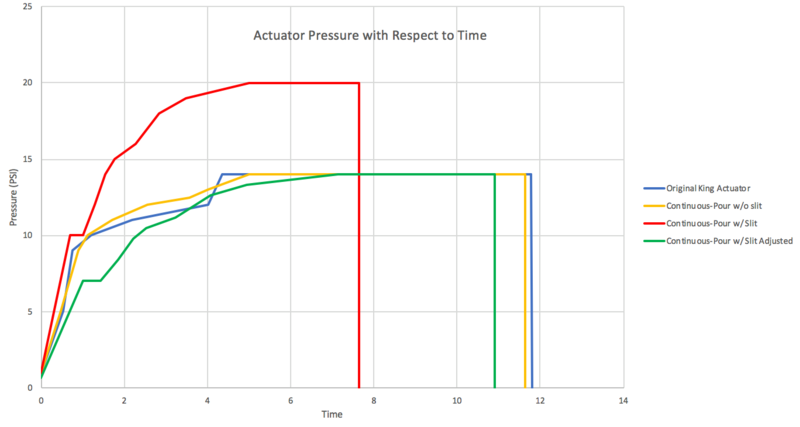
To confirm the quality of the King Actuator, we performed durability tests comparing various versions of the actuator and a PnueNet. We argued that solid tensile strength and ability to actuate with a high pressure airflow would accurately portray the quality and durability of the actuator. After fabricating actuators of comparable size, we inflated them using a Ryobi Power Inflator until they ruptured or delaminated. Using 240fps slow motion video, we noted PSI changes and when the actuator failed. This data shows us which actuator is able to withstand more pressure and which is the most durable for various applications.
You can view vidoes of these pressures tests here.
While collecting the data, we experienced inconsistencies in PSI output from the pump because we did not charge the battery between tests for the Final Slit actuator and the PnueNet. As a result, the data may have been scaled differently. To compensate for this, we assumed there was a direct correlation between the maximum recorded PSI and the output PSI, and scaled the data down by a ratio of the maximum PSI of one line to the average of the other two, normalizing the data. From analyzing both data sets and the video, it was evident our single body actuators far outperformed the PnueNets. While the PnueNets delaminated instantly, the other actuators, (The Original King and the Continous Pour with and without slits) survived longer. We were not able to record any data for the PnueNets because it delaminated and burst instantly. However, our actuators still suffered problems. Each of our actuators failed when an air pocket opened between the fabric and silicone. The reason for failure is similar among all of the actuator types; when scaled down, all of our actuators failed at a similar point, further justifying the issue between the seal.
Qualitative Testing
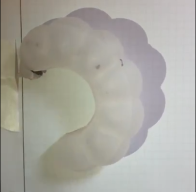
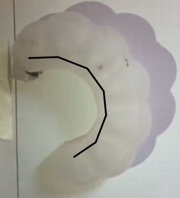
A major component of any pneumatic actuator is its ability to bend with applied pressure. We plotted the curve of the actuators and compared thier general shape.
| Original King | Continuous Pour (No Slits) | Continous Pour (With Slits) |
|
|
|
|

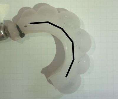
All of the actuators arched similarly, although the slotted continous pour expanded within each section, causing the actuator to bend more at the start. In addition, the Continuous Slotted actuator we used had a manufacturing defect where the internal bent the oneside, causing a non-uniform curvature.
Insert Qualitative Testing
One of the benefits of using a 3D printed insert is that we can change and play with the shape of the cavites formed in the actuator when the PVA is dissolved, giving it its modularity. We 3D printed a set of variable inserts to make actuators out of and see how they impact actuation. We tested some of the internals proposed and noticed no significant visual differences between the different internal shapes in terms of actuation. This is likely due to the fact that as air gets pushed into the cavities it tends to push in the same pattern, thus no matter the shape and size of the cavity the expansion of the cavity will remain the same shape. For the future we would like to create more actuators with these variable shapes and test more volumes out to see if it really has no effect on actuation. However we did notice that the more complicated the shapes got, the harded the actuators were to actuate and remove the inserts from.

Data Collection and Output for Pottery
Pottery Instruction
As stated, one of the goals of this project was to help teach students to throw a pot more effectively. In order to do this we observed our ceramics teacher throw a pot. The process is highly complicated, including individual finger and arm motion. In order to begin addressing this problem, we worked with Mr. Raeder to simplify the process of throwing a pot to squeezing the edges of a block of rotating clay with two fingers. We figured that if we can replicate the pressure which the teacher is squeezing the clay and output it to actuators attached to the fingers of students, we would be able more effectively teach students how to throw a pot.
In order to output the pressure to the actuator we had to gather data collected from the teacher throwing a pot. To do that we created a glove with pressure sensors attached the tips of the pointer fingers to read the pressure which the teacher is exerting on the block of clay. Using an arduino control board we created a method we dubbed Active Hand Recording (AHR), in which the the glove, a flex sensor map, is constantly polled at a fixed rate, and the data (the placement of the fingers) from the glove is recorded using the Motion Tracking File/Compressed Motion Tracking File (MCI/CMCI), and the MCI Compression Algorithm (MaRS). The AHR constantly polled data from the glove at a fast and fixed rate meaning that latency and high-level detail were not an issue; however, the AHR system comes at a price.
The Active Hand Recording Analysis
| Pros | Cons |
| - Allows for high detail levels | - High file sizes depending on quality |
| - Less processing power required | - Complex algorithm (MaRS) in processing side code |
| - Possible redundancy allows for less data corruption at higher polling speeds | - Bitrate and data flow concerns |
| - Higher speeds and more data provides a better insight into the movements. |
The AHR system works through a three-step process.
1. The Arduino poll information from the glove.
2. The values from the glove are sent to the computer.
3. The computer recording-relatively timestamps the data and save it into a MCI file.
All of this happens at a certain rate, which depends on the Serial baud output rate.
The processing of the AHR data using the MaRS algorithm works through a two-step process.
1. Seek the MCI file for value consistencies within a threshold.
- Example: The hand is motionless for half of a second
2. If a consistency is found, shrink it to one 'average' byte and set the timestamp of the motion(s) accordingly.
- Example: 'The motionless hand at 00:05, 00:05.15, 00.05.43, 00.05.62, 00.06' is shrunk to 'the motionless hand at 00:05-00:06.'
Note: The algorithm can take a long time to work depending on the duration of the motion capture and speed of the processor.
From all of this we are able to retrieve a graph of the pressure as it relates to time (in this case frames).
 We built a fluidic control board in order to control the output of air to the actuators. However we struggled with understanding how to control the pressure of the actuators using pressure regulators we purchased. This forced us to simplify the process further which was obviously not ideal. We corrected the noise and the input data into a square wave to make for easier control of actuation. We converted the recorded pressure into a scale with the minimum recorded pressure changed to 0.
We only used one hand because there was not enough space in the center of the pots to perform controlled actuation. While recording data, sensors were put on both the right and left hands. We noticed that the force applied the outside edge had a greater impact on the straightness of the pot, as on average the right hand, the outside hand, applied more force to the pot than the inside hand. We could not control for the vertical motion of the student, however we believe that after observation, mimicing the vertical position of the hand was intuitive.


This method proved to be ineffective because we oversimplified the process of throwing a pot. Our largest issue was in controlling the fluidic control board's output of pressure for a long duration of time. We experienced difficulties with keeping the pump continuously working over the duration of throwing the put and thus were unable to actually, accurately test the quality of the MaRS algorithm in teaching novices to throw pots.

If we were given more time we would have liked to moved towards a Passive Hand Recording (PHR) system. PHR is a method in which if the glove moves, the data is recorded, unlike AHR which constantly records hand movements, moving or not.
| Pros | Cons |
| - Less file size than AHR | - Latency concerns |
| - Detail can still be captured | - Incorrect threshold values may cause loss of detail |
| - Runs with less data transfer speed required | - False triggering may occur depending on threshold values |
| - Less data corruption | - No backup/redundancy |
We however did not manage enough time to fully develop this method.
The code used throughout this entire project can be found here.
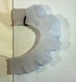
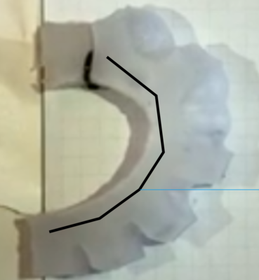
Image Analysis
In order to determine whether or not our MaRS algorithm was more effective in teaching students to throw pots, we had to perform image analysis on the pictures of pots thrown by a teacher, a student after instruction with a teacher, and a student wearing the actuators. We decided that a good metric of analyzing the pots thrown by the individuals was to analyze how straight each of the pots were. To do that we split each pot in half to get a profile view of the edges of the pot. We determined where the base lay and drew a vertical line up from the midpoint of the base. We then, using ImageJ, measured the the distances, in pixels, of various lines to calculate the standard deviation of the lines in relation to the center line. Each side of the pot was split up into different component lines (as shown in the annotated image below) to determine the straightness of the pot. The hypothesis was that if the pot was completely straight then the distance between either edge of the pot from the center line should be the same, measured by standard deviation. Each component line had no more than 100 data points extrapolated from it. Smaller lines had fewer distances measured becuase there was less area to measure. All of our data can be found here.

As stated on our previous page about gathering and outputting data, we were unable to successfully output the pressures and make the actuator inflate consistently and in time to aid the student in throwing a put. Therefore, we, unfortunately, were unable to test the validity of this method of teaching students how to throw a pot. However, the actuators did hold up while they worked, proving that the King Actuator can be used in vigorous applications.


Contributors
Meet the Team

Who are we?
We are a group of high schoolers (and three middle schoolers) from The Haverford School for Boys, located in the suburbs of Philadelphia, aspiring to innovate and explore the field of soft robotics.
Back Row from Left to Right:
Elijah Lee (8th Grade) - Elijah worked with Josiah to engineer the programs powering the project. He also worked to design, fabricate, and finalize the King actuator, as well as joining Bram with development on the Fluidic Control Board. In his spare time, he enjoys messing with electronics, rowing, and coding.
Josiah Somani (8th Grade) - Josiah is the lead programmer for the team and designed the recording and playback programs for the glove using Arduino C and Java. He enjoys watching Star Trek, trading crypto-currencies, and learning Blockchain technology.
Alexander Greer (Sophomore) - Alexander is the graphic designer for the team, and helps organize the design and documentation states of the projects. He competes with the school's VEX robotics team during the school year, where he and his team came fourth in the world in this year's competition.
Henry Sun (Junior) - Henry is one of the co-founders of the Haverford's Soft Robotics Team. He worked on designing and manufacturing the actuators and oversaw most of the actuator development. Henry is the head of the Entrepreneurship Club and the Beekeeping Club at Haverford. Henry is also the manager of the Varsity Basketball Team.
Bryce Broadus (Junior) - Bryce works with the manufacturing of actuators. Outside of soft robotics, Bryce enjoys playing football and furthering his interest in engineering.
Intel Chen (Junior) - Intel is the main photographer and cinematic director for the soft robotics team. He helps with documentation and, most notably, created the video. In his free time, Intel enjoys photography and programming for Haverford's VEX robotics team.
Calvin Costner (Junior) - Calvin works with the collection of data as well as making different variations of actuators. Outside of soft robotics, Calvin enjoys playing baseball and pursuing his interest in engineering.
Troy Barnes (Junior) - Troy aids in designing and manufacturing the actuators. He is also a student leader in Haverford's Diversity Alliance.
Edward King (Senior) - Ed is the developer and creator of the King Actuator and also helps the team work out any engineering issues that may arise. He is passionate about creating things and will be studying at the United States Military Academy at West Point next year.
Matthew Baumholtz (Senior) - Matthew helped write the wiki and advised the team throughout the process. He is a senior and co-founder of Haverford's Soft Robotics Team. In his free time, he competes on the varsity level in water polo and debate. He will be studying Economics and Computational Neuroscience at the University of Chicago next year.
Front Row from Left to Right:
Aditya Sardesai (Sophomore) - Aditya is a co-founder of the soft robotics team and works with the content of the wiki, data analysis, and the communication of the actuator designs. He is also a captain of the school's debate team and is part of the school's VEX robotics team.
Toby Ma (Sophomore) - Toby assists in making the pneumatic actuators as well as data collection. Toby is a member of the school's VEX robotics team, the school newspaper, Model UN, and the school's literary magazine.
Daniel Chow (Sophomore) - Daniel works with the design and creation of the pneumatic actuators, the development of the wiki, the fabrication of the polystyrene inserts, and the gathering and processing of data. He plays for the school squash team and is a member of the school's VEX robotics team.
Biagio DeSimone (Junior) - Biagio helped write sections of the wiki. He was also involved in creating the molds and actuators of the glove. Biagio also participates in Model UN and is an avid supporter of the Philadelphia Eagles.
Robert Esgro (Junior) - Robert is tasked with the collection of control data and is involved in the production of actuators. Robert is the captain of the Mock Trial team, an editor of the school newspaper, and a member of the varsity lacrosse team.
Safa Obuz (Freshman) - Safa helps with the development of the wiki as well as the design and fabrication of the actuators. He competes with the school's VEX robotics team and runs cross country.
Yeshwin Sankuratri (Sophomore) - Yeshwin led the image analysis team, analyzing the pots thrown by teachers and students. Outside of soft robotics, Yeshwin is an avid squash player and is a member of the school's literary magazine.
Not Pictured:
Bram Schork (8th Grade) - Bram is a middle schooler focusing on the development and circuit diagramming of the fluidic control board, along with the programming of other electronics. Bram enjoys tinkering with inventions and prototyping software along with playing water sports.


We would like to thank:
Ms. Golecki for helping us through every step of this project and sparking our interest in soft robotics
Mr. Raeder for giving us the inspiration for this project
Mr. Trocano for the help, guidance, and advice during this project and for letting us use the Chemistry Lab
Ms. Jacobs for helping us sew together the sensor glove
Ms. Snyder for letting us work in the Upper School Library
Ms. Brown for letting us work in her classroom