Background
While working on last year’s project, we noticed issues regarding the delamination of actuators that occurred while using the two-part mold. The delamination caused our edible actuators to have a relatively low success rate, as even the slightest amount of air sheared the air cavities from the base. This made the actuators unsuitable for rigorous actuation and multiple actuation cycles.
Evident from our project last year, we are passionate about increasing the accessibility to soft robotics. It allows for more students to have their interests in material science and engineering piqued the same way soft robotics piqued our interests in those fields. To increase accessibility, we set out to design an actuator that could be produced with ease. We hypothesized that the use of a soluble internal structure could be used to create the air chambers for inflation, making the fabrication process simpler. Our team believes that this process of fabrication has never been done before.
Our mentor implemented soft robotics into the engineering curriculum at our school. One of her students, Ed King, was building the Soft Gripper from the Resources for Educators when he too struggled with the delamination of the actuator. He then had an idea: rather than using a two-step process and have the structural integrity rely on the layers weakly fusing together, why not use a single mold to create the entire actuator in one go? The key to his new method, dissolvable inserts, would allow him to use a single mold to create actuators. No lamination required.
He decided to cast silicone around a polystyrene (styrofoam) insert and dissolve it using acetone after the cast has cured. This idea of soluble actuator inserts marked the beginning of the King Actuator.
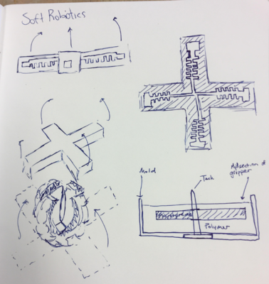

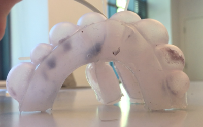
Figures 1, 2, and 3: Initial design sketches, first prototype, and first successful actuation
The images above show the conceptualization, the fabrication, and the actuation of one of Ed's first King Actuators. The difference in density of the silicone and styrofoam materials caused the styrofoam to float. While we were excited about Ed's innovation, we knew there were was room to improve, and thus, our iterative design process began.
At the same time, the ceramics teacher at our school, Mr. Raeder, approached us with a problem: he wanted a more effective method of teaching his students how to throw a pot. He described the difficulty of instructing complex, nuanced motions to his students. Mr. Raeder told us, "If a student’s relaxed hands could feel pressure to move the correct way using soft robotics, it would be very efficient and convenient.” We believe that using a glove similar to that described in Polygerinos et al. (2013) would be ideal in aiding a student's learning in ceramics and reduce the time necessary to become proficient in the art.

Figure 4: Mr. Raeder teaches a new student how to throw a clay pot
Our goal for the 2018 Soft Robotics Toolkit Competition was to create a single-pour actuator manufacturing process using a dissolvable insert in order to prevent delamination and increase actuator durability. From the start of our research, we defined our success as creating an easy-to-make and durable actuator design. In tandem to our project, we would like to develop the foundations for the teaching of ceramics through soft robotics. While our project is not centered around teaching ceramics, we believe that soft robotics has a place in teaching anything that requires muscle memory or complex, nuanced motions, and would like to make progress in that field with this new application.
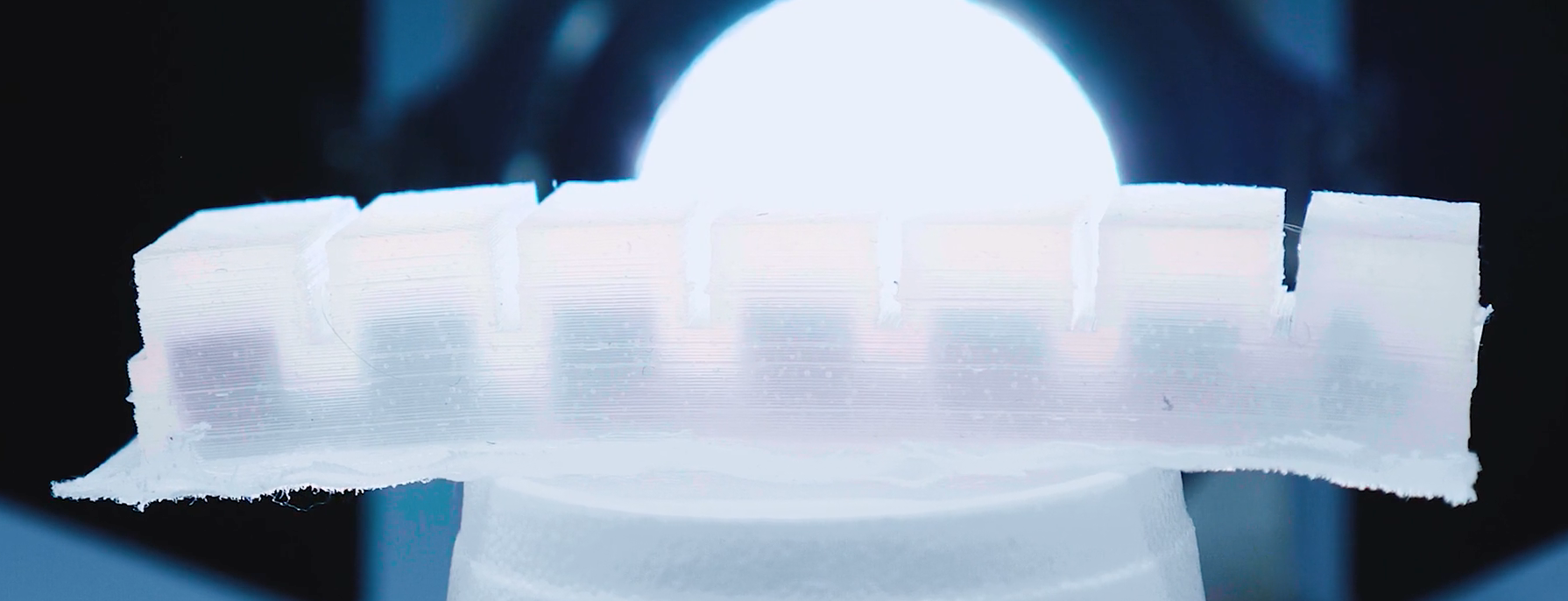
Figure 5: A King Actuator prior to the polystyrene insert being dissolved.

Design
Preliminary Actuator Design
While creating silicone-based actuators using the PnueNets, we encountered issues when attempting to seal the two portions of the mold. Due to the two parts of silicone curing separately, the seal between the bottom layer and the actuator itself was not completely air-tight, resulting in its delamination. In consideration for a simpler process and reliable actuator, we noted features we would like to have for an ideal actuator.
A continuous-pour mold was one of our priorities, as such a process would reduce the time required to fabricate an actuator and eliminate the issue of delamination. However, this brought the challenge of forming the actuator's insert structure, which needed to be removed from the mold in a single motion.
Edward King, a student at our school, conceptualized a system where the inserts inside the mold could be dissolved, creating an air pocket for actuation. King considered using materials such as polystyrene (styrofoam) for such a process. Another benefit we considered in our design of the insert-dissolving method was that the air pockets could now have more complex geometries. A two piece mold limits one’s air pockets to the shape of a rectangular prism. Different geometries such as circles, trapezoids, and parallelograms would now be possible.
Once we formulated the first design and a potential application to test the actuators, a styrofoam insert was manually cut and fit to a simple rectangular mold. We poured a different, transparent material, polydimethylsiloxane (PDMS), into the test cardboard mold so we could physically view the dissolving process. Upon first glance, the large deviation between the densities of each material caused the styrofoam to rotate and float upwards, rendering the actuator unusable in practice. However, as expected, the dissolving of the insert using acetone through a manually poked hole was quick and simple.
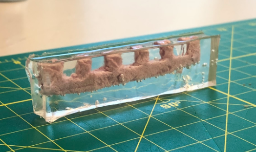
Figure 6: Polystyrene insert in clear PDMS mold
Another observation we made was that the manually poked hole (created previously using a Wilton brand cookie flooding etching tool) should, ideally, be built into the mold. This would be done to create consistency from actuator to actuator, to aid in airflow during actuation, and to help dissolve the Insert. After the first test, we considered using fabric on one end of the mold as an inextensible layer to help constrict that side, reducing the overall vertical volume of the actuator. After we finished the simple prototype to gain preliminary information about the style of actuator, we began our iteration on the first version.
Actuator Design Iteration and Fabrication
Version 1:
Once we realized the amount of precision needed when creating these actuators, we switched to using 3D-Printed PLA (polylactic acid) for the base molds, and PVA (polyvinyl alcohol) for the inserts. PVA is water soluble which ideal because a soluble insert allows us to utilize a one-pour process. We can remove the PVA using water after the silicone is cured, leaving the connected air chambers which allow for the inflation and bending of the actuators. Using PLA, we could mark each iteration of mold dimensions with color-coding printer filament. Also, another incentive for using PVA was to test a different material than stryofoam, as our tests with stryofoam were successful. These materials are easy to manipulate as we could 3D-print them and easily change their dimensions. We also transitioned to using EcoFlex™ 00-50 Two-Part Silicone for the actuator structure.
(See the Bill of Materials for more detailed information regarding the materials we used)
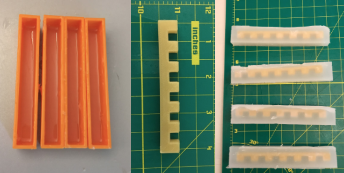
Figures 7, 8, and 9: 3D printed molds, a 3D printed insert, and completed V1 actuators
Dimensions:
- Orange Mold: 16.70 x 105.60 x 15.88 mm
- PVA Insert: 12.70 x 88.90 x 9.53 mm
Fabrication Process for First Iteration:
-
Lay down a single layer of fabric
-
Pour the mixed silicone halfway up the depth of the base mold
-
Place the insert centered in the mold
-
Fill rest of the mold with silicone
-
Wait for the mold to cure
-
Remove by pulling up the sides by hand
-
Dissolve the insert
In contrast to the styrofoam inserts, the PVA roughly maintained its position relative to the mold and did not float at all. Another key observation we made was about the dissolving process of the PVA. Before using the compound we tested the water solubility of the PVA in an experiment. Although it was apparent the material required an extensive amount of time to dissolve, the data was not representative of the actual dissolving process inside an actuator. First, it was difficult to expose the entirety of the PVA insert to the heated water through a minuscule hole. In doing so we tore the side walls of the actuator from inserting the nose of the pipet and creating pressure with water.
Version 2:
In the next iteration, we focused on changing the dimensions so there was less height and more width. The extra width added material to the sides so the actuator would not tear, and we compensated for less overall height with more layers of fabric. We also decided to switch back to the polystyrene inserts as they with our current methods could dissolve. However, still challenged with the floating issue of the styrofoam, we noted the inserts and constricting fabric could vertically swap their position such that, if the inserts floated upwards, they would only move towards the side with the fabric.

Figure 10: Swapping the position of the fabric and inserts
Dimensions:
- Yellow Mold: 23.05 x 105.80 x 12.70 mm
- PVA Insert: 12.70 x 88.90 x 3.18 mm
Fabrication Process for Second Iteration:
-
Fill the mold with mixed silicone
-
Lay two layers of fabric on top
-
Attach strips of velcro
-
Wait for the silicone to cure
-
Dissolve
Version 3:
As we were brainstorming various designs for an actuator to assist one's motion, we decided to use strips of velcro to allow the actuator to be attached to a finger. This would be more versatile than a glove as the as there is no limitation on the user’s hand size.

Figures 11 and 12: Attaching velcro to a mold and velcro attachment testing
(Note: We tested the velcro technique using a PnueNet base in the image above)
Althought the previous actuator iteration was generally successful as it could actuate multiple times, assited in applying force when worn, and did not tear or break while doing so, there were still a few issues. The dissolution hole still had to be manually made, which is counter-intuitive to the goal of simplicity, and makes the dissolving process more tedious. The actuators also, comprising of simply a block with an air channel, had difficulty inflating and bending in the same motion as the PneuNet actuators. What our actuator lacked, which most soft actuators have, are incisions, or slits, to help increase the range of motion. In our case, our actuators had a wide range of motion, but at the cost of the stretching of the silicone. Each air pocket, when inflated, looked and behaved similarly to the inflation of a balloon. The material did not rip due to our solution's elasticity, yet the long-term reliability was questionable. This led us to a design that utilized sectioned air pockets and attachable inserts that could be anchored by the mold.

Figure 13: 3D models of the final mold and insert
In between the iterations one series of the 3D printed mold suffered from scaling issues where the size of the parts did not match, one series lacked the vertical indents, and one packed the air pockets too closely.
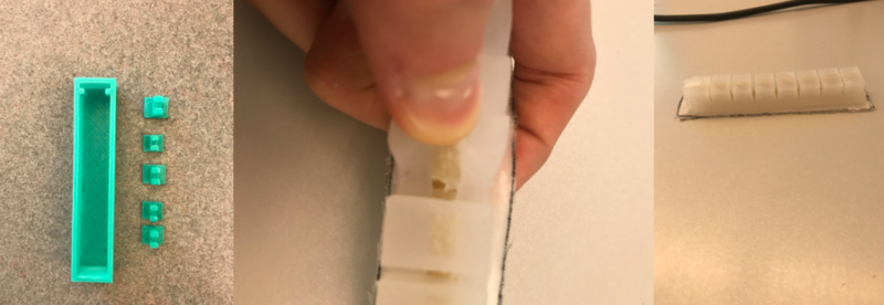
Figures 14, 15, and 16: a 3D printed mold and claws, a fabrication error, and a completed actuator
Of the final generation, we could only completely remove the PVA insert of one the molds through a painstaking process. We decided that if we were to continue, and use the actuator for applications like a motion assisted glove, we should test casting inserts into a mold, and then dissolving said inserts.
Dimensions:
- Slot Mold: 25.40 x 123.83 x 15.88 mm
By the nature of us 3D printing the inserts, we can print inserts that are different shapes and mess with the geometry that way, giving it its modularity. We created actuators using these new geometries, as described in the testing section, but found little difference in actuation.
You can download CAD files for these uniquely shaped inserts here.

Fluidic Control Board and Sensor Glove
Fluidic Control Board Design
We used the fluidic control board instructions with some modifications, as our end application projection required variable PSI output based on information we collected. We controlled the PSI through independent pressure regulators rather than using PWM to have a pressure applied and the end of each fingertip. In addition, we added an LCD to help debug code. As for recording data we tried both Flex and Force sensors, ultimately choosing Force Sensors because we did not care about how much the finger bent, but rather how much force is being applied to the pot.
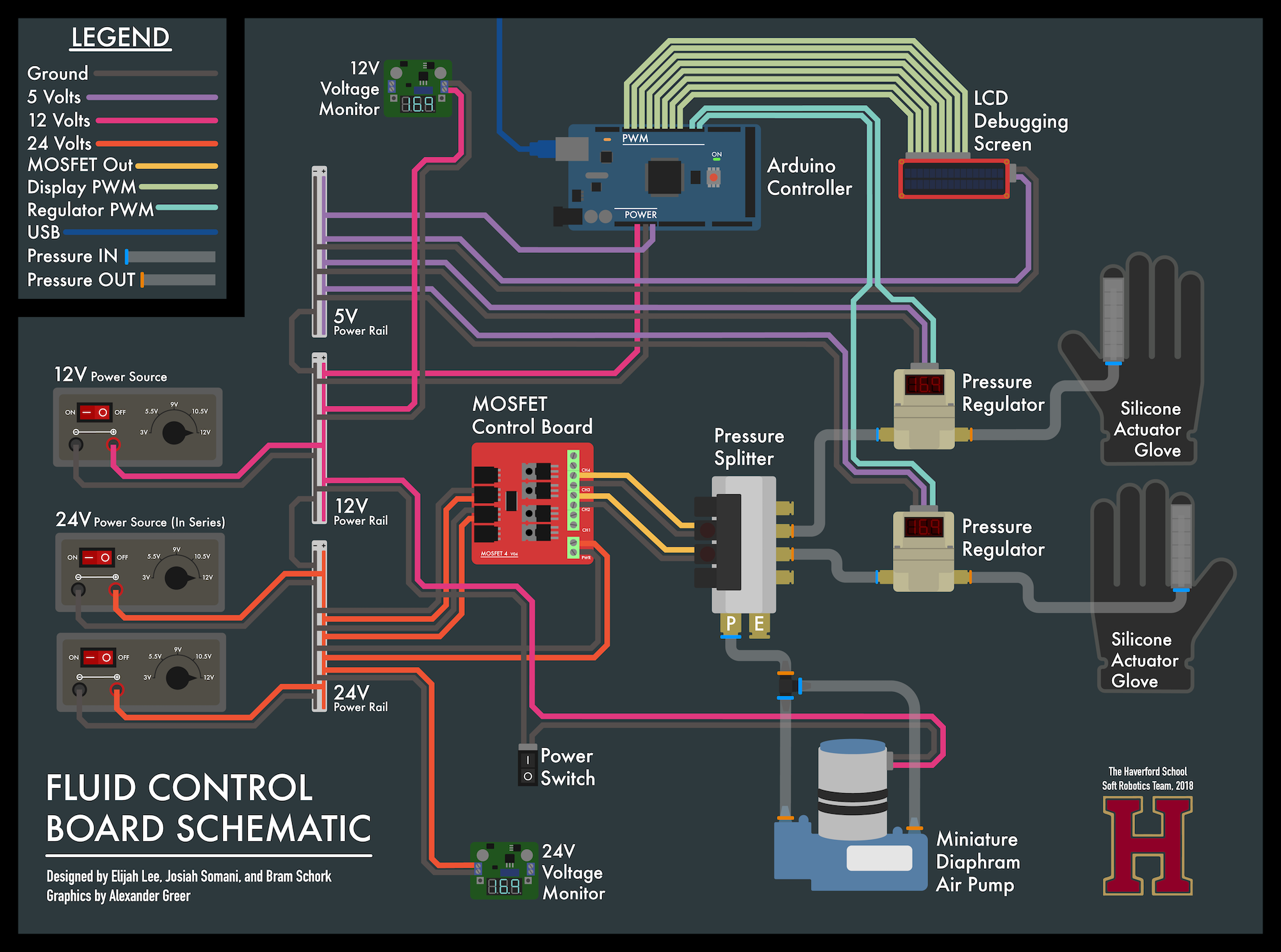
Figure 17: The schematics and circuit diagram of the fluidic control board
Pressure Sensing Glove Iteration
Using the Pressure Sensing Glove we were able to record the hand motions of an articulate ceramicist. Through trial and error, we created a glove that housed the sensor cable robustly such that it would not interfere with data collection. Originally, we used a Flex sensor hot glued on a latex glove. The glue’s bond was poor and broke near instantly. After switching to the Force Sensor we electrical taped the sensor and extension on the exterior of the glove. Worried that contact between the clay and any electrical components could end up being messy and damage the hardware, we resorted to finally stitching all the components to the interior of the glove. In this manner, all components were hidden and we followed through recording our data.
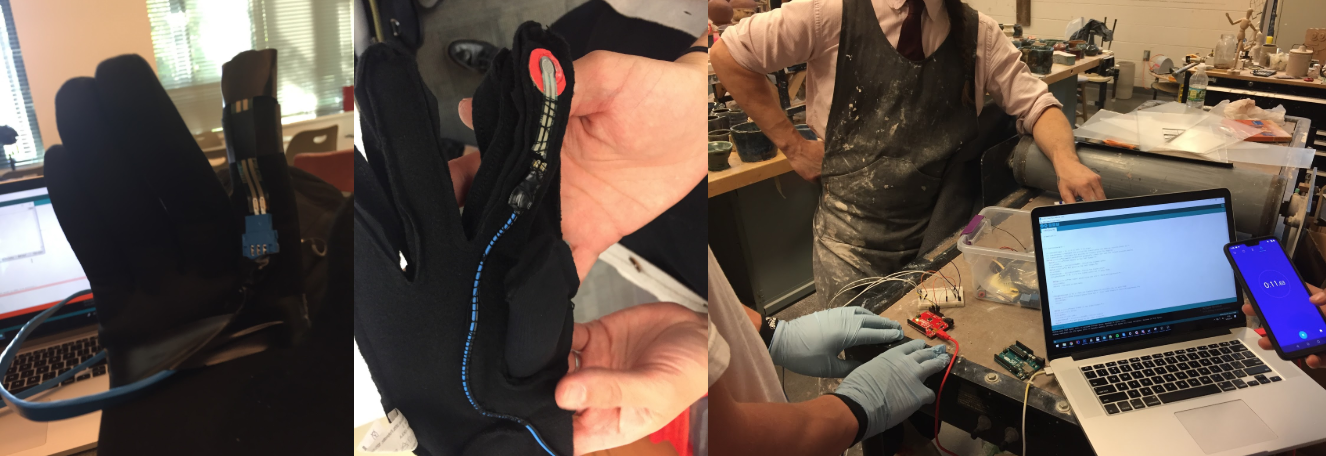 Figures 18, 19, and 20: The pressure sensing glove, the sewn on force sensor, and a student testing the sensors
