ConTact Sensors
![]()
The ConTact Sensor is a force and contact area sensitive sensor developed at rombolabs at the University of Washington that can be easily integrated into most soft-robotics designs. Using the fluidic conductive medium already inherent in soft robots, the sensor can sense the force and size of an object pressing into it. The main sensing element is a conductive fluid core with conductive rubber leads and the force and size is derived by measuring the resistance and pressure changes of the fluid. The sensor is mostly fabricated from silicone rubber with minimal external components. This guide provides details on how the sensor works, how to fabricate the sensor and how the sensor was tested and validated.
The name ConTact is from the main principle of sensing: a Conductive fluid and the sensor itself being a Tactile sensor
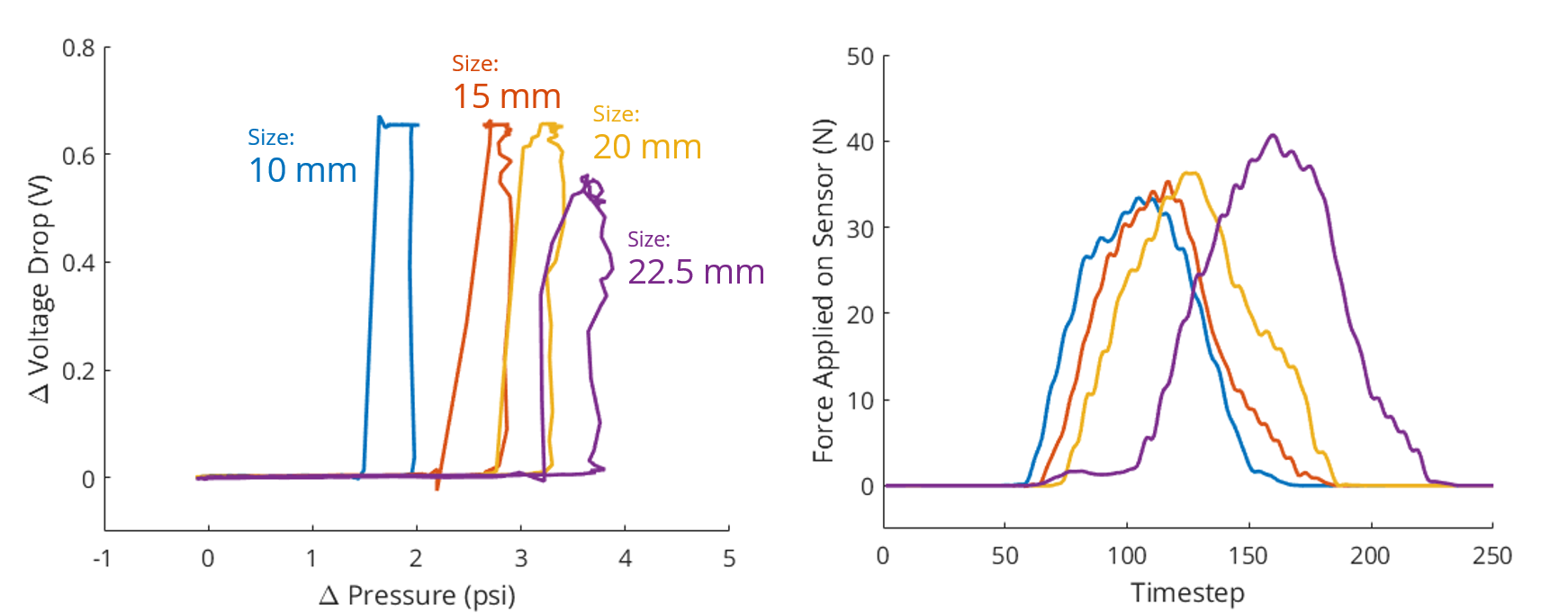
Below are examples of raw sensor readings. When objects of different sizes are pressed against the sensor with the same amount of force, the sensor shows distinct responses for each object size. The details of how to derive the size and force of the objects are presented in the Testing section.
Design
Motivation


Soft robots rely on fluids for actuation through the modulation of pressure. Similarly, soft sensors rely on the same properties for measurement. However, while the fluids used in soft robotics are most likely to be either gaseous (air) or liquid (water), in most applications the fluid properties themselves e.g. electrical resistance or temperature are seldom exploited for sensing. Here, we present the idea of using multiple modalities of the fluid medium as a sensor to gain richer overall sensing capabilities. For instance, we might want to not only know the amount of force an object is applying to a soft sensor, but the size and shape of the object too. This guide presents a liquid based soft sensor capable of estimating both the force and area an object is acting upon it.
Concept

In soft robots that use fluid media to sense or actuate, the amount of force or deformation being subjected to it can be derived by measuring the pressure increase or decrease of the fluid medium. Another interesting property is the electrical resistance of the fluid medium. According to Pouillet's law \(R = \frac{\rho L}{A}\), assuming constant resistivity \(\rho\), the amount of resistance can vary from the amount of cross sectional area (\(A \)) change and length (\(L\)) in a resistive media. We exploit this property by using conductive fluid in the soft sensor, herein salt water. Measuring both resistance and pressure change, we can sense both the bulk deformation and change in cross sectional area, from which we can estimate the size or shape of the object the soft sensor is touching.


In its simplest form, the sensor can be a rubber tube with two conductive leads filled with salt water, as shown above. However, casting the sensor into more complex embodiments enables much more interesting uses.
Components
The soft sensor itself consists of three major components: The sensor body, the conductive interface to the fluid and the conductive fluid itself.

The Sensor Body
The sensor body is a silicone rubber rectangular cuboid with a lengthwise circular channel with conductive rubber ends and rubber tubes to transmit pressure.
In practice, the sensor body can be any shape that is able to be cast using traditional silicone casting methods. The only limitation is the requirement of an internal cavity or channel to house the conductive fluid.
The Conductive Fluid
The fluid used in this guide is simply saline (salt) water at 5 wt%. (5 g NaCl + 95 g water)
One major limitation of using an ionic fluid is the ion build up at the two conductive ends when measuring resistance using standard methods, such as using an ohmmeter. To circumvent this, the resistance must be derived from the voltage drop across the sensor from a low voltage alternating current source. This is similar to typical water conductivity measurement methods. More details are explained in this section.
The Conductive Interface
An electrically conductive medium forming an electrical pathway between the conductive fluid and the external measurement system. Using conductive rubber as the interface, fabricated with chopped carbon fiber mixed with silicone rubber, we can reduce the drastic change in stiffness between the soft inner components and the wires of the measurement system. Another benefit of using this specific form of conductive rubber is the ability to cast it into any arbitrary form.
Measuring Resistance with AC
The Requirement of Alternating Current in Data Acquisition

Salt water (aqueous sodium chloride NaCl) is an ionic fluid that consists of positive (sodium, Na+) and negative (chloride, Cl-) ions. These ions flow freely in the solution and are attracted to voltage potentials introduced to the solution, for instance, if you’d place a negatively charged plate in a saltwater solution the positively charged sodium ion (Na+) will start to migrate towards the plate. This poses a problem when measuring resistance in the traditional sense because an ohmmeter applies a small known voltage and measures the current in order to calculate the resistance. What would follow when measuring the resistance of a ionic fluid is the small voltage applied charges the two leads of the ohmmeter, one positively and one negatively, thus leading to ions pooling towards their attractor. The solution itself then becomes capacitive, storing a potential, and discharges into the ohmmeter causing a erroneous reading. Thus, applying any direct current (DC) voltage to the sensor will cause it to store charge and render the resistance measurement impossible.

This phenomenon can be verified by simply attempting to measure a saltwater solution with a multimeter for duration of 30 seconds and switching to voltage measurement - there will be a potential of a few millivolts that decays, additionally, swapping the leads with result in a negative reading of a few millivolts.


To circumvent this issue, we measure the voltage across a known resistor in series with the sensor while applying alternating current as the voltage source - this is known as a voltage divider. The alternating current ensures that there is no charge stored in the sensor since the ions do not get a chance to pool towards either lead/electrode. The same principle is found in water conductivity meters. An example circuit is shown above. When the sensor changes its resistance, the voltage drop across the sensor and the known resistance changes and thus the resistance of the sensor can be calculated from \(V_M=V_S \times \frac{R_{KNOWN}}{R_{SALT} + R_{KNOWN}}\) , which gives \(R_{SALT}=R_{KNOWN}\times\frac{V_S-V_M}{V_M}\).
Most data acquisition devices with analog input and output, such as the NI USB-6351 should have the capability to drive and measure small negative voltages and thus can provide and measure the sinusoidal AC signals required for the sensor. However, given the correct circuitry, an operational amplifier can be used to generate an AC signal and the rectified sensor voltage response can be measured using a standard microcontroller with an analog-to-digital converter (ADC), thus reducing the cost of the overall project greatly at the inconvenience of analog circuitry.
Fabrication
This section details the steps required for fabricating one sensor and how to setup the sensor for measurement. The fabrication of the sensor is mainly a three-step process: casting the conductive rubber (the interface), casting the sensor body and injecting the conductive fluid.
Overview

|
This step is mainly casting conductive rubber using chopped carbon fiber strands and silicone rubber |

|
This step is casting silicone around the conductive rubber to embed them and provide an interface between the outside and inner cavity of the sensor. Once casted a rubber tube and leads are attached. |

|
Sensor setup is simply adding conductive fluid to the sensor. In this guide, the conductive fluid is salt water. |

|
A rough guideline is provided for hardware setup to get readings from the sensor
|
Bill of Materials
This section is split into each individual component of the sensor. A generic name is provided with the supplier for ease of substitution. Every item can be replaced at your own discretion.
Conductive Rubber

3D Printed Parts
These parts can be printed with ABS or PLA. They are designed to require minimal support material.Casting Materials
- 3 mm chopped carbon fiber (.125" Chopped Carbon - 1 lb - Amazon)
- Rubbing alcohol (not pictured, any generic household rubbing alcohol works)
- Shore 25 A platinum cure silicone rubber (Platsil Gel-25 - Brick in the Yard)
- 10 ml Syringe (10ml Oral Syringe - Amazon)
- Stirring sticks (Mixing sticks - Brick in the Yard)
- Mixing cups
Mold Parts
- 4 mm steel rod (Low-Carbon Steel Rod - McMaster Carr)
Equipment
- Multimeter or Ohmmeter (not pictured)
- Precision weight scale with 0.01 g resolution (AMIR Digital Kitchen Scale, 500g/0.01g - Amazon)
Sensor Body

3D Printed Parts
These parts can be printed with ABS or PLA. They are designed to require minimal support material.- Mold body (Download)
Casting Materials
- Shore 25 A platinum cure silicone rubber (Platsil Gel-25 - Brick in the Yard)
- Stirring sticks (Mixing sticks - Brick in the Yard)
- Mixing cups
- Conductive rubber ends
- 4 mm OD - 2 mm ID semi-clear silicone tubing (PUTC4-10 - MiSUMi)
- Silicone adhesive (Silpoxy - Smooth-on)
Mold Parts
- 4 mm steel rod (Low-Carbon Steel Rod - McMaster Carr)
Equipment
- Weight scale (AMIR Digital Kitchen Scale, 500g/0.01g - Amazon)
Conductive Fluid

Materials
- Table salt
- Water
- Food coloring
Equipment
The equipment listed here is simply what we had at hand during the project, each instrument can be replaced with any equivalent piece of hardware.
Sensing Pressure
- Pressure sensor (ABPMANT100PG2A3 - Mouser) (I2C)
- Microcontroller (Teensy 3.5 - PJRC)
- Pressure sensor (ABPMANN004BGAA5 - Mouser) (0 - 5 V)
Sensing Resistance
- Data acquisition device capable of +-5V analog output (NI USB-6351 - National Instruments)
- Assorted resistors, should cover at least 1 kOhm to 1MOhm range (Resistors - Amazon)
Step 1: Conductive Rubber

The conductive rubber components are used to conduct electricity from the conductive fluid to the external leads. The steps shown here are adapted from Andrew Quitmeyer's guide on Instructables.

|
STOPCarbon fiber strands are extremely lightweight and can become airborne. Ensure you are wearing the proper safety equipment before continuing. We recommend:
|

|
Prepare the mold by sliding the 4 mm steel rod through the holes on the side of mold |

|
Using a sharp blade, carefully cut the tip of the syringe off to make a 8 mm diameter orifice. Remove the syringe's plunger and attach the syringe attachment on to the syringe with a quarter turn. It will be helpful to stand the syringe upright. One way is to cut a syringe sized hole in a cup like shown. |

|
In a stirring cup, weigh 0.5 grams of chopped carbon fiber followed by 1 gram of rubbing alcohol |

|
Stir the mixture of carbon fiber and rubbing alcohol thoroughly until the fibers are dispersed like shown. Pour out any excess alcohol and squeeze the fibers to remove as much alcohol as possible. |

|
Pour in 20 grams of Part A of the silicone rubber (PlatSil Gel-25) followed 20 grams of Part B of the silicone rubber. Note: Only substitute the silicone rubber with platinum-cure silicone rubber and follow instructions to yield 40 grams of total rubber. |

|
Stir the mixture thoroughly. Please keep in mind that PlatSil Gel-25 has a pot life (time before the mixture is too thick to pour) of 5 minutes. Stir until the mixture has a consistency like shown. To ensure conductivity, you can also measure the resistance of the mixture. The steps provided here should yield a resistance of 1 - 2 kOhms depending on where you measure. |

|
Pour the mixture into the syringe attachment up to the beginning of the threads as denoted with the yellow dots. |

|
Screw on the cap of the syringe attachment, the carbon fiber and silicone rubber mixture should flow down into the syringe. Note: For ease of cleanup, let the mixture remain in the attachment until it is dry and then peel off the cured rubber. |

|
Remove the syringe attachment and insert the syringe's plunger. The mixture might immediately flow out. |

|
At this point the mixture is extremely viscous and is difficult to spread. Dispense the mixture into the mold by slowly dragging along the length of the mold and use the face of the syringe to press down on the dispensed mixture. |

|
Using a flat bar or the stirring stick, press down on the mixture into the mold. Try to remove as much voids as possible. It is okay if the mixture protudes from the top. We found that pressing down and moving lengthwise in short strokes in a single direction helps fill the mold. |

|
Wait at least 60 minutes (or according to manufacturer's suggestion) before demolding. The conductive rubber is very easy to cut with a sharp blade (X-acto or cutter blade). Trim the excess conductive rubber off the top of the mold. |

|
With a twisting motion, pull the 4 mm steel rod out of the mold and then demold the conductive rubber. Use a small tool to pry the conductive rubber out of the mold at the ends and pull. |
|
|
Using a sharp blade, cut the conductive rubber lengthwise into 1 cm long pieces. The resistance of the conductive rubber from one end to the other should be 1-2 kOhms. This concludes the steps for the fabrication of the conductive rubber. |
Step 2: Sensor Body

The sensor body is simply casted from silicone with embedded conductive interfaces at the ends.

|
Prepare the mold by inserting the 4 mm steel rod and suspending the conductive rubber ends at both ends of the mold. |

|
Leave small gaps between the end of the mold and the conductive rubber as shown. |

|
Pour 25 g each of Part A and Part B of the silicone rubber (PlatSil Gel-25) to a total of 50 g into a mixing cup. |

|
Stir the mixture. Periodically scrape the sides and bottom of the cup to ensure proper mixing. Please take into account the limited pot life of 5 minutes of the mixture. Vacuum degassing of the mixture is suggested but not required. |

|
Pour the silicone rubber mixture into the mold up to the brim. Tap the bottom of the mold against a table repeatedly to remove any large air bubbles trapped inside. Wait for the silicone rubber to completely cure. |

|
Remove the 4 mm steel rod by either twisting it out with a pair of pliers or securing the rod in a vise and twisting out the mold. After the rod is removed, demold the sensor body from the mold using a small tool to pry out the sensor at the ends of the mold. |

|
The completed sensor body |

|
Cut the silicone tubes into 40 cm and 5 cm long sections and insert them into the sensor body as shown. Insert the end of the tubes only up until half of the length of the conductive rubber. Inserting the tube in too far might cover up the whole area of the conductive rubber in contact with the salt water, rendering the conductive rubber useless. |

|
Apply liberal amounts of silicone adhesive (Sil-Poxy) at the ends of the sensor body and let dry. Any outer voids from the molding process can also be patched up at this point. |

|
Insert the male 0.254" pins with the short side facing the sensor as shown. Glue the pins in place with silicone adhesive. |
|
|
Once the adhesive has dried, the sensor is complete and ready to be charged with conductive fluid. |
Step 3: Sensor Setup
Before hooking up the sensor to the equipment, we need to first fill the sensor with conductive fluid. In this guide, we use 5 %wt saline solution, which is simply 5 parts salt to 95 parts water by weight.

|
Weigh 10 grams of salt in a container |

|
Add 190 grams of water to total of 200 grams of solution. Filling the sensor only requires about 5 ml of saline. The solution is prepared in bulk due to the ease of weighing. |

|
Add 3 drops of food coloring. Coloring the saline is important for checking for air bubbles within the sensor. |

|
Stir well until the solution is homogeneously colored. |

|
Using a syringe, pull about 9 ml of the solution. There will be some air bubbles along with dissolved gasses within syringe. Follow the instructions in this video to vacuum degas the bubbles. Of course, vacuum degassing the whole container is also fine. |

|
Once degassed, the solution is ready to be injected into the sensor. |

|
Hold the sensor up at the ends of the silicone tubes in to a "U" shape like shown. Doing so will prevent air bubbles from being trapped while filling the sensor. |
|
|
Slide the syringe tip into the short end of the sensor. |

|
Slowly fill the sensor by depressing the syringe plunger in short strokes while staying vertical. |

|
Make sure there are no air bubbles between the two conductive ends within the sensor body. Refill if necessary. |

|
Plug a stopper in one end of the sensor, remove the syringe and plug in another stopper at the other end. |

|
Remove the plug from the longer silicone tube and plug the tube into the pressure sensor. Squeezing the end while inserting the tube will ensure that air is not trapped between the pressure sensor and the fluid. The images here are for illustrative purposes only. Please wire up your hardware accordingly. |

|
Plug in leads from the voltage divider circuit or data acquisition hardware.
The images here are for illustrative purposes only. Please wire up your hardware accordingly. |
|
|
The sensor is now complete and ready to be used! |
Step 4: Equipment Setup
The equipment setup provided here serves only as a guideline. The only requirement is the ability to measure pressure in the line and measure the resistance (or voltage) between the leads of the sensor. A high level overview is presented below.

Measuring Pressure
If the digital (I2C) version of the pressure sensor is being used, connect the SDA, SCL, VCC, and GND pins to the respective pins on the microcontroller. This guide will not provide detailed instructions for communicating using I2C, please consult the datasheet for the specific microcontroller.
If the analog version of the pressure sensor is being used, connect the 0-5V or 0-3.3V output from the sensor to the analog input of the microcontroller or data acquisition hardware.
Measuring Resistance
Data acquisition device setup:
- Analog out: 2 Vpp sine wave (+ - 1V) at 100Hz
- Analog in: RSE mode (Single-Ended-Grounded Reference) with voltage divider circuit as explained in the Measuring Resistance with AC page
Choosing the Resistor
To get the most dynamic range out of the sensor, the resistance of the resistor in the voltage divider should closely match the sensor's resistance at rest.
Choosing the resistor is done by following process:
- Choose an arbitrary resistance, a good starting point is 80 kOhms.
- Measure the response of the sensor at rest. Let's say we get a \(V_M\) of 0.2 volts.
- Calculate the resistance of the saline water with \(R_{SALT}=\frac{R_{KNOWN} \times V_{M_{RMS}} }{V_{S_{RMS}}-V_{M_{RMS}}}\)
- Select a resistor with a resistance close to \(R_{SALT}\). If the voltage at rest is not near 0.5 volts, reiterate by repeating steps 1 to 3.
Testing
To test and calibrate the sensor we used objects with known lengths to press against the sensor placed on top of a load cell.
Overview
As seen in the video, the sensor was loaded with wooden sticks of various lengths. Force was manually applied until the electrical resistance of the sensor changed. To monitor this changes in real-time we used the Robot Operating System (ROS) as a backend for our data collection. Using ROS eases systems integration across multiple systems and hardware. We will not go into detail on how the systems integration is performed.
Disclaimer: The raw data feed shown in the video was collected in a seperate but similarly performed data collection session.
Testing hardware
- National Instruments USB-6351 Data Acquisition (DAQ) system for measuring resistance
- Teensy 3.5 for reading pressure sensor
- LoadStar iLoad Pro
- Various sections of wooden sticks with known length
Testing software
- Robot Operating System
- rosserial_python
- LabVIEW & LabVIEW ROS
Raw Sensor Data
The raw data from the sensor is in two separate data streams: the resistance (the voltage drop) and the pressure. Plotted below are raw (zeroed) readings from the sensor - similar to what is shown in the overview video.

The sensor was loaded as shown in the above video. We recorded a continuous datastream for all measurements and sectioned the data time-wise according to the object impinging the sensor.

The sensor exhibits an interesting behavior where the voltage drop (resistance) starts changing as the pressure increase starts to saturate. The point of transition from pressure to voltage drop sensitivity depends on the contact area of the object impinging the sensor. Using this knowledge, and the ground truth data (the loadcell), we can calibrate the sensor in the following modalities.
Force
As the voltage drop (or resistance) picks up in sensitivity after the pressure change saturates, we use the following formula for derving the force applied to sensor:
\(F=(P+V\times K_C)\times K_F\)
where:
\(F :\) force
\(P:\) pressure
\(V:\) voltage drop
\(K_C:\) calibration constant
\(K_F:\) calibration constant
\(K_F\) is approximate from the following linear fit, where the raw value is \(F=P+V\times K_C\) where \(K_C\) is 0.21 (heuristically found). We used a \(K_F\) of 8.16.


Contact Area
As we used objects that are larger than the width of the sensor, we can use the length of the object in contact with the sensor instead of the area. Since the voltae drop starts to change at a particular pressure for each object length, the formula for deriving the contact length is:
\(l = P \times (V > V_{threshold}) \times K_A\)
where:
\(l :\) contact length
\(P:\) pressure
\(V:\) voltage drop
\(V_{threshold}:\) threshold voltage
\(K_A:\) calibration constant
For the sensor in the guide, we used \(V_{threshold}=0.3\) and \(K_A =6.22\). For clarification \((V>V_{threshold})\) is 1 if V is greater than the threshold voltage and 0 if not.
From our recorded data, we can plot the following. It is clear that the sensor can discern between objects of various sizes given the object applies enough force to the sensor to trigger the transition.

Our \(K_m\) is derived from the following linear fit

Downloads
![]()
Authors: Pornthep Preechayasomboon, Gaurav Mukherjee, Eric Rombokas
The ConTact Sensor is a force and contact area sensitive sensor developed at rombolabs at the University of Washington that can be easily integrated into most soft-robotics designs. Using the fluidic conductive medium already inherent in soft robots, the sensor can sense the force and size of an object pressing into it. The main sensing element is a conductive fluid core with conductive rubber leads and the force and size is derived by measuring the resistance and pressure changes of the fluid. The sensor is mostly fabricated from silicone rubber with minimal external components. This guide provides details on how the sensor works, how to fabricate the sensor and how the sensor was tested and validated.
The name ConTact is from the main principle of sensing: a Conductive fluid and the sensor itself being a Tactile sensor
Below are examples of raw sensor readings. When objects of different sizes are pressed against the sensor with the same amount of force, the sensor shows distinct responses for each object size. The details of how to derive the size and force of the objects are presented in the Testing section.