RoboisE
Overview
In the Motivaion and Inspiration section, we explain about the motivation for the design of our 4-legged robot, RoboisE. The Design section contains an explanation of why we chose to use Dielectric Elastomer Actuators (DEAs) to drive the motion of our robot and how we employed DEAs to move the 4 limbs of the RoboisE, which resembles a tortoise (see Figure 1), to bring about directed motion.
In the Fabrication section, we document the process of the making and assembly of the RoboisE's body, actuators, and electrical connections. In the Testing section, we describe the actuation of the RoboisE and include videos of the RoboisE in motion.
Figure 1: Schematic of Roboise design
Get to know us...
We are undergrads from Nanyang Technological University, Singapore. Our team comprises "Captain" Lan, Zaki, Febby and Marco (not from Tropoja). Just in case you are curious how we look like, this is an image of us, discussing intensely, exhibiting such amazing synergy. As you can see in the team photo, our Captain Lan is enthusiastically gesticulating with both hands, telling us that "the whole is greater than the sum of its parts".

Team photo [left to right: Marco, Zaki, Lan, Febby]
|
|
Motivation and Inspiration
WALL-E
Our first inspiration comes from the movie, WALL-E. The movie features a dystopian view of the earth in year 2800. WALL-E is left on earth to clean it while human beings are evacuated from the planet on giant starliners due to its uninhabitable environment. We are particularly interested in the stability and resilience of WALL-E which enable it to manouvre around unknown terrain. An advantageous feature of WALL-E is its low centre of mass.

Figure 2: Image of WALL-E (Walt Disney)
Tortoise limbs
Our robot's structure and motion are inspired by tortoises. Tortoises have to bear the load of their own houses yet they are able to move on 4 teeny tiny limbs. Similarly, our goal is to have a stable, untethered structure with legs that serve the dual function of supporting the weight of the robot's body and electronics as well as bringing about directed motion. Thus, we named our robot RoboisE [tortoise robot].

Figure 3: Image of tortoise crawling on 4 stubby limbs
Design

Concept
Overview
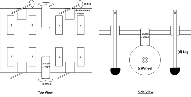
This is the structure of the robot in its entirety. To understand the big picture, refer to Figure 4 when reading the sections below.

|
Figure 4: Schematic of entire robot
Diaphragm actuators
We used diaphragm actuators to produce horizontal motion. A pair of circular (prestrained) DEAs are locked in position by external rigid components. A long, rigid T-shaped component is placed between the centres of the two stretchable actuators (see Figure 5). The length of the T-shaped component is longer than the fixed distance between the two circular actuators, thus, the actuators are held in tension with stress radiating from the centres of the films.
When one actuator from the pair is actuated whilst the other is not, the actuated film will increase in area and there will be a difference in compressive stress provided by the two actuators onto the T-shaped component. Specifically, the activated film will offer less mechanical resistance to the T-shaped component compared to the non-activated film. This results in a net horizonal force pushing the T-shaped component away from the non-activated film and towards the activated film (see Figure 5).
This horizontal motion of the T-shaped component can be utilised to produce the robot's leg movements.

|
Figure 5: How the diaphragm actuators produce horizontal motion
How actuation translates to leg movement
To couple the horizontal motion of the rigid T-shaped component to the ground on which the robot is resting, a rigid shaft with hemispherical base, which we call the "leg" of the robot, is used to connect the T-shaped component to the ground so that mechanical contact between the two is established. The top of the leg is screwed to the protruding tip of the T-shaped component at A (see Figure 6) and the shaft of the leg is screwed to the edge of the board that offers structural support to all the actuators, at B (see Figure 6). Since both of these screwed points at A and B are pin supports, the leg is free to rotate about the point of connection at B, but not translate with respect to the T-shaped component and the edge of the board.
When the left actuator is activated, the T-shaped component translates horizontally to the left and the top of the leg, which is pinned to the T-shaped component, moves from A to A' (see Figure 6). Since the shaft of the leg is pinned to the board at B, the base of the leg swings from E to E' (see Figure 6). This creates a horizontal leftward displacement of the entire robot with respect to the ground. Note that all this while, the positions of the diaphragm actuators with respect to the board where they are planted, marked C and D on the board, are unchanged (see Figure 6).

|
Figure 6: Leg movement
Materials
We have chosen to use Dielectric Elastomer Actuators (DEAs) to drive the motion of our robot. DEAs have the advantage of being completely electrically controllable, which would simplify the process of activating and coordinating the different actuators in the system using a programmable circuit. Furthermore, DEAs are lightweight compared to traditional robots with motors and heavy metallic parts, which makes for improved mobility. Lastly, DEAs are relatively easy to fabricate by hand.
We used VHB 4910 acrylic as the Dielectric Elastomer (DE) because it is an elastomer capable of producing large strains under high tension. Furthermore, it is a well-known and documented material in the field of DEAs.

Figure 7: VHB 4910 acrylic
For the compliant electrodes, we used carbon black (Sigma Aldrich) in conjunction with carbon conductive grease (MG Chemicals) because they are easy to apply by hand and do not require procedures like spray coating. This combination of conductive materials produces compliant electrodes whose conductivity is not compromised much when stretched in tension.

Figure 8: Carbon black

Figure 9: Carbon conductive grease
To connect the compliant electrodes to wires leading to the power supply, we used conductive carbon tape and copper tape. The tapes bridge the gap between the soft actuator films and the relatively rigid wires, thus reducing the risk of the actuators getting punctured by accident.
The rigid structural components of the robot were 3D printed because with 3D printing, the shape and dimensions can be customised to our requirements. Furthermore, 3D printed parts are lightweight, which is necessary to reduce impediments to motion.

Figure 10: 3D printing in progress
Electrical circuit
For the RoboisE circuit, the initial plan was to use an Arduino Nano microcontroller to activate the motion sequence of the robot with an IR remote control. The microcontroller was linked to 4 relays to connect to 4 different transformers. Each transformer was connected to 2 legs of the robot. IR sensor was also connected to Arduino for wireless communication to activate the motion sequence. The entire circuit was powered by 2 Lithium Ion Battery 18650 cells with 3.5 volt and 3200 mA H each.

Figure 11: Circuit with 4 transformers and Arduino Nano
However, at a later stage of the robot's development, we realised that we need to be able to control the actuation of each actuator independently of one another. For that to be possible, 8 transformers are required for 8 independent sequences for the 8 actuators. Unfortunately, due to time constraints, we did not manage to code the motion sequence of 8 independently controllable actuators into Arduino, thus, we settled for manual operation of the circuit. On top of that, we only possessed 6 transformers and not 8 so we could only actuate 3 pairs of actuators (i.e. 3 legs).
The following is our manually operated circuit with 8 switches to activate the choreographed motion sequence. The entire circuit is powered by a direct high voltage power source.
Figure 12: Manually operated circuit for independent control of each actuator
Arduino code for RoboisE circuit
Attached below
| roboise_arduino_code_for_circuit.txt | 6 KB |
Fabrication
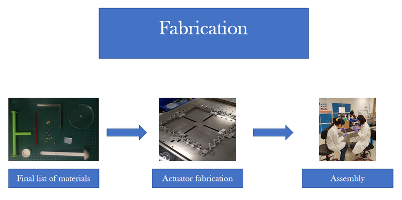
Final list of materials and parts
Actuators:
- VHB 4910 acrylic elastomer
- Carbon black (Sigma Aldrich)
- Carbon conductive grease (MG Chemicals)
- Carbon tape
- Copper tape
- Custom-made rigid acrylic rings
- Bottle caps
Legs:
- Rigid T-shaped component
- Rigid shaft with hemispherical base
Other components:
- Acrylic board with laser-cut grooves
- Rigid C-shaped component
- Screws
- Nuts and bolts
- Aluminium L-section
- Steel L-section
- Acrylic wheels
Electrical components:
- DC power source
- Wires
- Breadboards
- DC-DC step-up transformers
- Tactile switches
- Arduino

Figure 13: Miscellaneous parts
Fabrication of actuators and other components
Diaphragm actuators
The diaphragm actuators are easy to fabricate, however, precision and dexterity are required.
Here is our step-by-step procedure for fabricating the DEAs:


Figure 14: Procedure for fabricating diaphragm actuators
In total, 4 pairs of circular actuators (8 single actuators) are needed to move all 4 legs of the robot (1 pair for each leg).

Figure 15: 8 completed diaphragm actuators
Other components
The T-shaped components, the legs and the C-shaped components were modelled using 3ds Max software and 3D printed. 4 T-shaped components, 4 C-shaped components and 4 legs are needed to complete the structure of the robot.
To ensure that the horizontal motion of the T-shaped component translates to forward and backward motion of the leg, a pin support has to be established between the tip of the protruding segment of the T-shaped component and the top of the leg. Thus, a blind hole is made at the tip of each T-shaped component as shown in (see Figure 16), where a screw can be inserted to pin the leg to the T-shaped component. The flat circular bases at the two other ends of the T-shaped components are to reduce the stress on the already taut circular actuators and thus reduce the risk of rupture.

Figure 16: T-shaped component
For the leg, shown in Figure 17, the through hole at the top of the leg allows us to pin the top of the leg to the T-shaped component using a screw. Similarly, the slot in the middle of the leg enables us to establish a pin support between the middle of the leg and the edge of acrylic board that holds all the actuators in position. The slot allows the connection between the middle of the leg and the edge of the board become a sliding pin support to accommodate changes in the distance between the tip of the T-shaped component and the pin at the edge of the board while the actuators are being activated. The hemispherical base of the leg is so that the leg can partially roll on the ground, which reduces the resistance to motion arising from drag.

Figure 17: Leg
The C-shaped component is pictured in Figure 18. Its purpose is to provide external compressive stress onto the pair of acrylic rings to counter the tension experienced by the highly stretched out diaphragm actuators.

Figure 18: C-shaped component
Assembly of robot and establishment of electrical connections
After all the actuators have been fabricated, the next step is to assemble the robot.
Step-by-step procedure:
1. Screw and assemble all the components, aside from the diaphragm actuator devices, onto the large acrylic board with customised grooves (e.g. steel and aluminium L-shaped connectors, wheels and legs) as shown in Figure 19.
2. After the legs and wheels have been attached to the acrylic board, position the diaphragm actuators on their designated spots in the grooves in the acrylic board (refer to Figure 20). There should be 4 pairs of diaphragm actuators; each pair has a T-shaped component in between the centres of the inner sides of the circular films, and each pair has a C-shaped component holding the two acrylic rings of the diaphragm actuators together to balance the high tension in the stretched out elastomer films.
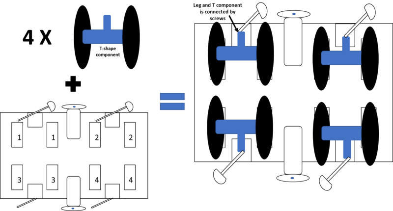
Figure 20: Installation of actuators onto supporting structure
3. Attach the copper tapes sticking out of the diaphragm actuators to wires leading to the electrical supply. Be careful to ensure that opposite polarity of the electrodes on opposite sides of the same film. Each actuator should be able to be activated independently of the others.
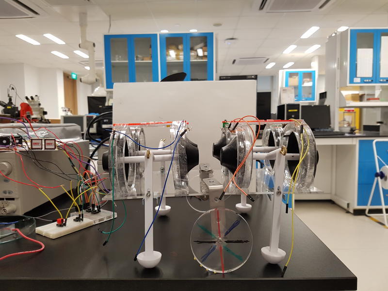
Figure 21: Completed robot
Testing
After all the actuators have been fabricated, the next step is to assemble the robot.
Step-by-step procedure:
1. Screw and assemble all the components, aside from the diaphragm actuator devices, onto the large acrylic board with customised grooves (e.g. steel and aluminium L-shaped connectors, wheels and legs) as shown in Figure 19.
2. After the legs and wheels have been attached to the acrylic board, position the diaphragm actuators on their designated spots in the grooves in the acrylic board (refer to Figure 20). There should be 4 pairs of diaphragm actuators; each pair has a T-shaped component in between the centres of the inner sides of the circular films, and each pair has a C-shaped component holding the two acrylic rings of the diaphragm actuators together to balance the high tension in the stretched out elastomer films.
Figure 20: Installation of actuators onto supporting structure
3. Attach the copper tapes sticking out of the diaphragm actuators to wires leading to the electrical supply. Be careful to ensure that opposite polarity of the electrodes on opposite sides of the same film. Each actuator should be able to be activated independently of the others.
Figure 21: Completed robot
Choreography of leg motion

Figure 22: Cycle of steps to displace robot
The motion of the legs can be descibed as a sequence of stages that form a cycle (see Figure 22) which can be iterated as many times as necessary to achieve translation of the robot in the same direction. In each stage, only 1 leg is shifted while the others are kept in the same position. This is to sequentially alter the distribution of weight on the 4 legs of the robot to prepare the centre of mass of the robot to translate forward. If all 4 legs of the robot move in the same direction simultaneously, there would be no forward displacement of the entire robot because the weight distribution amongst the 4 legs remains unchanged and the robot would simply swing back to its original position once the actuation voltage is removed.
In stage 1, all 4 legs are actuated in the same direction (e.g. all 4 front films are actuated making all the legs swing backwards). In stage 2, 1 of the hindlegs is actuated in the opposite direction (e.g. 1 of the hindlegs swings forward) while the other 3 legs are kept actuated in the original position. In stage 3, the other hindleg is then actuated in the same direction as the first hindleg while keeping the positions of the forelegs unchanged (e.g. 2 forelegs of actuated backwards, 2 hindlegs actuated forwards). In stage 4, 1 of the forelegs is actuated in the same direction as the 2 hindlegs. In stage 5, the last stage, the other foreleg is actuated in the same direction as the rest of the legs. At the end of the cycle, all four legs are shifted simultaneously such that the robot takes the same configuration as in stage 1 and the cycle repeats.
Video demonstrations
|
|
Many failed attempts
In this video, we show several of our failed trials. Initially, the robot was supported only on its 4 legs. We found this problematic because the legs were bearing too much load, thereby inhibiting its motion. Prior to developing the final leg motion sequence we present in 4.1 Choreography of leg motion, we tried other motion sequences and found that the robot would not displace forward if all or 2 of the legs were activated in the same direction simultaneously. To produce net displacement, the distribution of weight amongst the 4 legs need to be altered methodically.
|
|
Motion of the RoboisE
In this video, only 3 of the legs were working as we only possessed 6 transformers so we could only actuate 3 pairs of actuators independently. Furthermore, the switches on the circuit were manually operated due to a lack of time to code the motion sequence into Arduino. Nonetheless, we managed to achieve some displacement of the robot by following the choreographed motion sequence (see 4.1 Choreography of leg motion).
Limitations and suggestions for future work
One limitation of our current prototype is that it has many wires sticking out of it to connect the actuators to external breadboards. This poses hazard in case a live wire gets exposed. Furthermore, the wires prevent the robot from moving too far away from the electrical circuit and increases the risk of the robot tripping over the wires. If we had more time to work on the robot, we would attempt to make the robot untethered by drilling and constructing additional compartments on the body of the robot wherein to contain the circuit boards, transformers, and batteries. To accommodate the additional weight, we might have to consider adding more wheels to increase the mobility of the robot.
Another feature we can add to the robot is the ability to do turning motion. This would require alterations to the way the wheels are connected to the robot's body; we would need to install the wheels within swivel casters so that the wheels can swivel/ swerve and roll to steer changes in direction. In addition, we need to develop new sequences to the choreography of leg movements for turning motion.
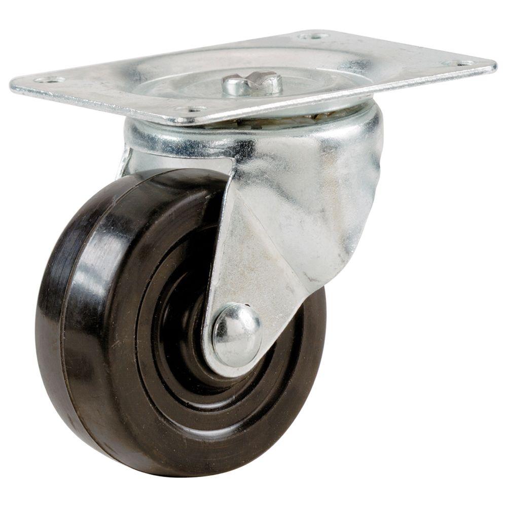
Figure 23: Swivel caster
To reduce the hassle associated with the manual operation of the circuit, it would be helpful to code the motion sequence of the robot, with the ability to independently control each of the 8 actuators, into Arduino. This way, the robot can be controlled using the IR remote control. Perhaps we can program the system to begin the cycle of steps at the press of one button, continue iterating the motion sequence loop, and break the cycle at the press of another button.
Lastly, a possibility to explore for future work is for the robot to swim in water, much like a turtle (which would be a step-up from tortoise motion).

Figure 24: Upgrade from tortoise to turtle