Fabrication
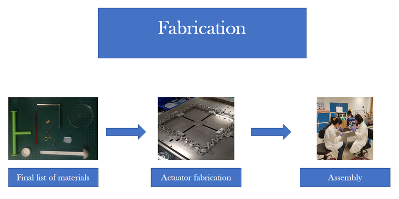
Final list of materials and parts
Actuators:
- VHB 4910 acrylic elastomer
- Carbon black (Sigma Aldrich)
- Carbon conductive grease (MG Chemicals)
- Carbon tape
- Copper tape
- Custom-made rigid acrylic rings
- Bottle caps
Legs:
- Rigid T-shaped component
- Rigid shaft with hemispherical base
Other components:
- Acrylic board with laser-cut grooves
- Rigid C-shaped component
- Screws
- Nuts and bolts
- Aluminium L-section
- Steel L-section
- Acrylic wheels
Electrical components:
- DC power source
- Wires
- Breadboards
- DC-DC step-up transformers
- Tactile switches
- Arduino

Figure 13: Miscellaneous parts
Fabrication of actuators and other components
Diaphragm actuators
The diaphragm actuators are easy to fabricate, however, precision and dexterity are required.
Here is our step-by-step procedure for fabricating the DEAs:


Figure 14: Procedure for fabricating diaphragm actuators
In total, 4 pairs of circular actuators (8 single actuators) are needed to move all 4 legs of the robot (1 pair for each leg).

Figure 15: 8 completed diaphragm actuators
Other components
The T-shaped components, the legs and the C-shaped components were modelled using 3ds Max software and 3D printed. 4 T-shaped components, 4 C-shaped components and 4 legs are needed to complete the structure of the robot.
To ensure that the horizontal motion of the T-shaped component translates to forward and backward motion of the leg, a pin support has to be established between the tip of the protruding segment of the T-shaped component and the top of the leg. Thus, a blind hole is made at the tip of each T-shaped component as shown in (see Figure 16), where a screw can be inserted to pin the leg to the T-shaped component. The flat circular bases at the two other ends of the T-shaped components are to reduce the stress on the already taut circular actuators and thus reduce the risk of rupture.

Figure 16: T-shaped component
For the leg, shown in Figure 17, the through hole at the top of the leg allows us to pin the top of the leg to the T-shaped component using a screw. Similarly, the slot in the middle of the leg enables us to establish a pin support between the middle of the leg and the edge of acrylic board that holds all the actuators in position. The slot allows the connection between the middle of the leg and the edge of the board become a sliding pin support to accommodate changes in the distance between the tip of the T-shaped component and the pin at the edge of the board while the actuators are being activated. The hemispherical base of the leg is so that the leg can partially roll on the ground, which reduces the resistance to motion arising from drag.

Figure 17: Leg
The C-shaped component is pictured in Figure 18. Its purpose is to provide external compressive stress onto the pair of acrylic rings to counter the tension experienced by the highly stretched out diaphragm actuators.

Figure 18: C-shaped component
Assembly of robot and establishment of electrical connections
After all the actuators have been fabricated, the next step is to assemble the robot.
Step-by-step procedure:
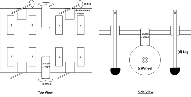
1. Screw and assemble all the components, aside from the diaphragm actuator devices, onto the large acrylic board with customised grooves (e.g. steel and aluminium L-shaped connectors, wheels and legs) as shown in Figure 19.
2. After the legs and wheels have been attached to the acrylic board, position the diaphragm actuators on their designated spots in the grooves in the acrylic board (refer to Figure 20). There should be 4 pairs of diaphragm actuators; each pair has a T-shaped component in between the centres of the inner sides of the circular films, and each pair has a C-shaped component holding the two acrylic rings of the diaphragm actuators together to balance the high tension in the stretched out elastomer films.
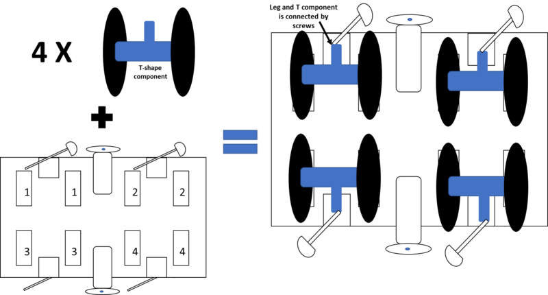
Figure 20: Installation of actuators onto supporting structure
3. Attach the copper tapes sticking out of the diaphragm actuators to wires leading to the electrical supply. Be careful to ensure that opposite polarity of the electrodes on opposite sides of the same film. Each actuator should be able to be activated independently of the others.
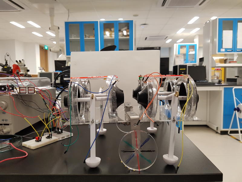
Figure 21: Completed robot