Testing
After all the actuators have been fabricated, the next step is to assemble the robot.
Step-by-step procedure:
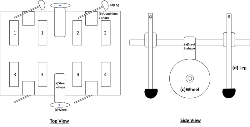
1. Screw and assemble all the components, aside from the diaphragm actuator devices, onto the large acrylic board with customised grooves (e.g. steel and aluminium L-shaped connectors, wheels and legs) as shown in Figure 19.
2. After the legs and wheels have been attached to the acrylic board, position the diaphragm actuators on their designated spots in the grooves in the acrylic board (refer to Figure 20). There should be 4 pairs of diaphragm actuators; each pair has a T-shaped component in between the centres of the inner sides of the circular films, and each pair has a C-shaped component holding the two acrylic rings of the diaphragm actuators together to balance the high tension in the stretched out elastomer films.
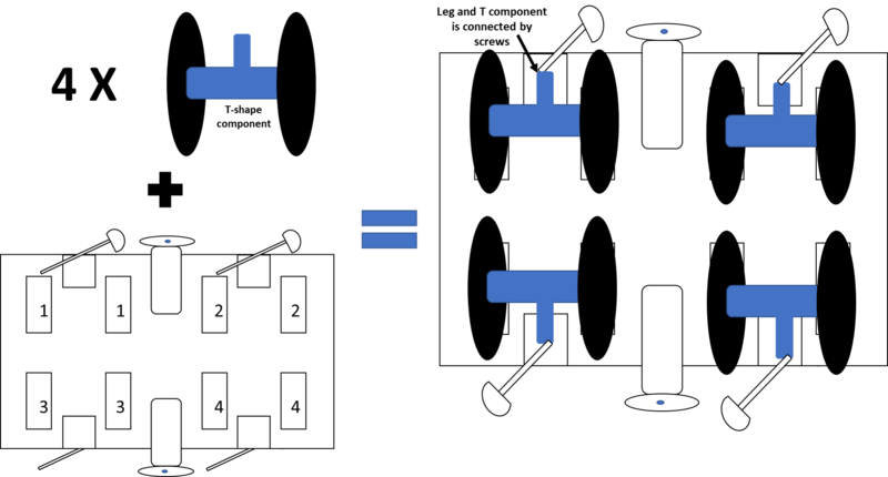
Figure 20: Installation of actuators onto supporting structure
3. Attach the copper tapes sticking out of the diaphragm actuators to wires leading to the electrical supply. Be careful to ensure that opposite polarity of the electrodes on opposite sides of the same film. Each actuator should be able to be activated independently of the others.
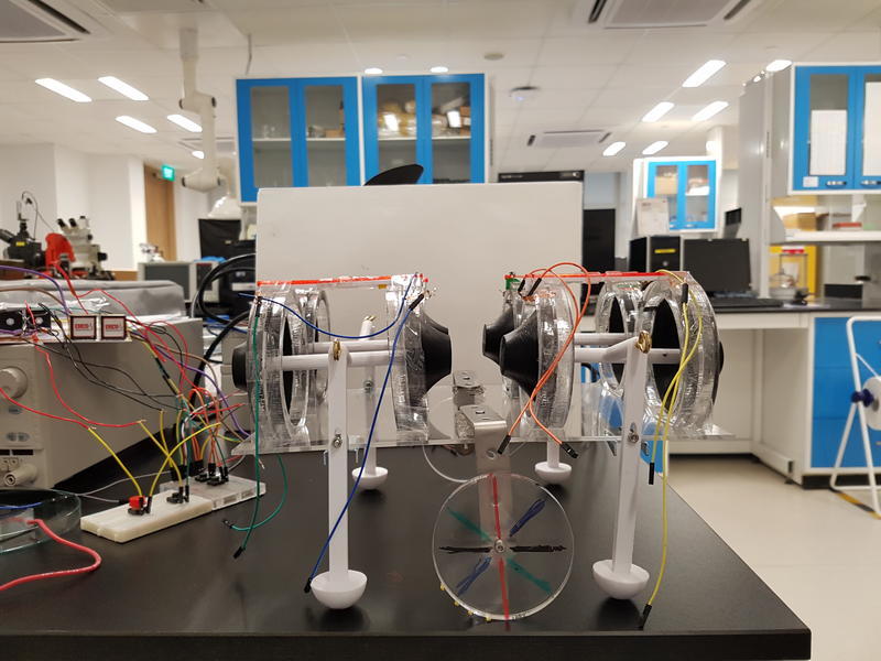
Figure 21: Completed robot
Choreography of leg motion

Figure 22: Cycle of steps to displace robot
The motion of the legs can be descibed as a sequence of stages that form a cycle (see Figure 22) which can be iterated as many times as necessary to achieve translation of the robot in the same direction. In each stage, only 1 leg is shifted while the others are kept in the same position. This is to sequentially alter the distribution of weight on the 4 legs of the robot to prepare the centre of mass of the robot to translate forward. If all 4 legs of the robot move in the same direction simultaneously, there would be no forward displacement of the entire robot because the weight distribution amongst the 4 legs remains unchanged and the robot would simply swing back to its original position once the actuation voltage is removed.
In stage 1, all 4 legs are actuated in the same direction (e.g. all 4 front films are actuated making all the legs swing backwards). In stage 2, 1 of the hindlegs is actuated in the opposite direction (e.g. 1 of the hindlegs swings forward) while the other 3 legs are kept actuated in the original position. In stage 3, the other hindleg is then actuated in the same direction as the first hindleg while keeping the positions of the forelegs unchanged (e.g. 2 forelegs of actuated backwards, 2 hindlegs actuated forwards). In stage 4, 1 of the forelegs is actuated in the same direction as the 2 hindlegs. In stage 5, the last stage, the other foreleg is actuated in the same direction as the rest of the legs. At the end of the cycle, all four legs are shifted simultaneously such that the robot takes the same configuration as in stage 1 and the cycle repeats.
Video demonstrations
|
|
Many failed attempts
In this video, we show several of our failed trials. Initially, the robot was supported only on its 4 legs. We found this problematic because the legs were bearing too much load, thereby inhibiting its motion. Prior to developing the final leg motion sequence we present in 4.1 Choreography of leg motion, we tried other motion sequences and found that the robot would not displace forward if all or 2 of the legs were activated in the same direction simultaneously. To produce net displacement, the distribution of weight amongst the 4 legs need to be altered methodically.
|
|
Motion of the RoboisE
In this video, only 3 of the legs were working as we only possessed 6 transformers so we could only actuate 3 pairs of actuators independently. Furthermore, the switches on the circuit were manually operated due to a lack of time to code the motion sequence into Arduino. Nonetheless, we managed to achieve some displacement of the robot by following the choreographed motion sequence (see 4.1 Choreography of leg motion).
Limitations and suggestions for future work
One limitation of our current prototype is that it has many wires sticking out of it to connect the actuators to external breadboards. This poses hazard in case a live wire gets exposed. Furthermore, the wires prevent the robot from moving too far away from the electrical circuit and increases the risk of the robot tripping over the wires. If we had more time to work on the robot, we would attempt to make the robot untethered by drilling and constructing additional compartments on the body of the robot wherein to contain the circuit boards, transformers, and batteries. To accommodate the additional weight, we might have to consider adding more wheels to increase the mobility of the robot.
Another feature we can add to the robot is the ability to do turning motion. This would require alterations to the way the wheels are connected to the robot's body; we would need to install the wheels within swivel casters so that the wheels can swivel/ swerve and roll to steer changes in direction. In addition, we need to develop new sequences to the choreography of leg movements for turning motion.
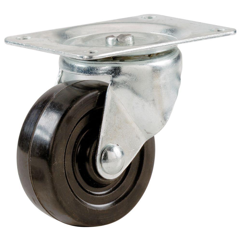
Figure 23: Swivel caster
To reduce the hassle associated with the manual operation of the circuit, it would be helpful to code the motion sequence of the robot, with the ability to independently control each of the 8 actuators, into Arduino. This way, the robot can be controlled using the IR remote control. Perhaps we can program the system to begin the cycle of steps at the press of one button, continue iterating the motion sequence loop, and break the cycle at the press of another button.
Lastly, a possibility to explore for future work is for the robot to swim in water, much like a turtle (which would be a step-up from tortoise motion).

Figure 24: Upgrade from tortoise to turtle