Laser Cut Molds for PneuNet Bending Actuators

 PneuNets (pneumatic networks) are a class of soft actuators originally developed by the Whitesides Research Group at Harvard. The PneuNet actuator technology has been a seminal soft robotics innovation and can be considered one of the basic building blocks for silicone based soft robotic designs.
The Soft Robotics Toolkit contains files and instructions for 3D printing molds to cast PneuNet bending actuators, but another way of fabricating molds is by means of a laser cutter. Using a laser cutter is often faster than using a 3D printer, which makes this method a feasible alternative for rapid prototyping of new designs or manufacture of a large number of molds. A laser cutter also often comes with a larger build volume than a 3D printer and can therefore create larger coherent PneuNets.
This documentation set contains files and detailed instructions to support the fabrication of four different PneuNet bending actuators. It also describes how to use these molds for casting actuators and two simple solutions for control and actuation. The mold design and fabrication procedures described are general and can be replicated to yield other designs.
The four included mold designs have been used for teaching hands-on soft robotics workshops aimed at introducing participants to basic soft robotic components, fabrication techniques, and actuation principles at the IT University of Copenhagen and Aalto University and at workshops conducted at ICRA 2018 and Pixelache Festival 2016.

Design
Included Designs
The design files were created in Adobe Illustrator by aggregating shapes drawn with the Line and Ellipse tools. The designs are saved as a vector graphics file that can be used with a laser cutter. Molds for four different bending actuators are included - a leaf shape, a triangle, and two rectangles:

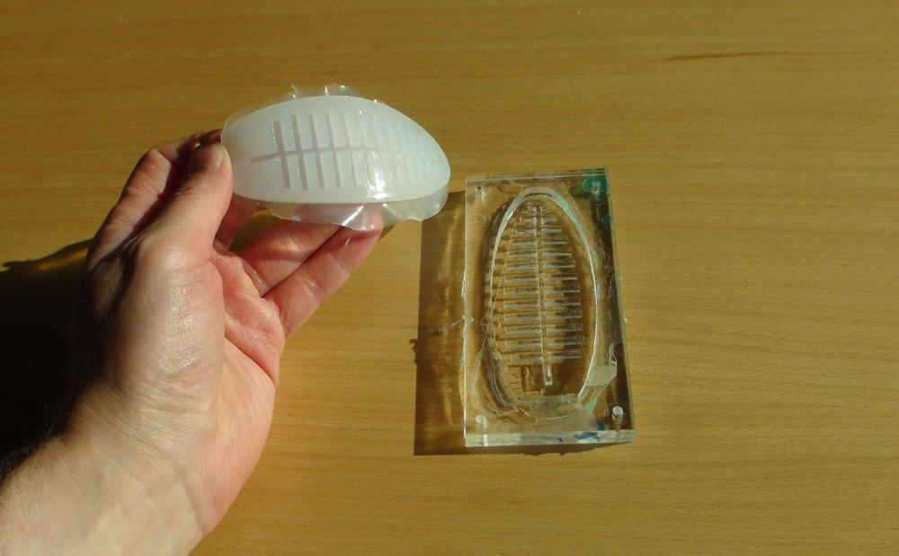
Each actuator mold consists of a top, middle, and bottom part that are laser cut in acrylic and subsequently glued together.

To create the leaf shaped mold, for instance, the parts marked in blue below are used:

Design Procedure
The following procedure was used to generate the included design files for laser cutting molds.
First the shape and dimensions of the actuator is decided upon based on its intended usage (see e.g. this publication and this publication).
To draw the design for a mold, it is easiest to start with the fishbone structure that generates the interior compartments of the pneumatic networks. The Line tool automatically gives the length of the line drawn, which makes it easy to use for this purpose.
Select the Line tool and choose a stroke width that is interpreted as a cut line by the laser cutter (usually below some threshold e.g. 0.1pt.). Start by drawing the two first compartments and the channel that connects them:

After this, select the 8 line segments that make up the bottom compartment and the channel (shown in blue below):

Make a copy of them and place the copy below the two compartments to make a third compartment (shown in red below):

Continue in this fashion by selecting and copying compartments and channels until you have the amount of compartments needed (Note: Select and copy multiple compartments and channels once you have generated more of the structure). Finally, the bottom compartment can be generated by copying the top compartment and channel and rotating them 180 degrees. With this compartment in place, the fishbone structure is complete:

After the fishbone strucure has been drawn draw the outline of the actuator and the mold (e.g. with the Rectangle tool):

Add holes for screws (using the Ellipse tool):

Now make two copies of everything drawn so far. Delete elements in each of these to make the designs for the top and bottom mold parts:

Save the finished design in a vector graphics file format e.g. .ai, .pdf, or .svg.
Mold Fabrication
This section gives detailed step-by-step instructions for fabricating a mold to cast a PneuNet bending actuator out of acrylic sheet material by using a laser cutter. A top, middle, and bottom part are laser cut from the acrylic sheet and then glued together to create the mold. For an experienced user of the tools and equipment needed, the whole process can be done in approximately 20 minutes (followed by 20 minutes for the acrylic glue to cure).
Acrylic has been found to be a good material to use for creating the molds as it is easy to laser cut and glue together. It also has a hard smooth surface which makes it easy to remove the cast silicone parts. Transparent acrylic is preferential, as the acrylic glue used cures when exposed to UV light.
Bill of Materials
To create the molds, the following is needed:
Materials
- Acrylic sheet of 3-6mm thickness
- Acrylic glue (ACRIFIX® 1R 0192)
- M3 bolts (with a length that is greater than three times the thickness of the acrylic sheet)
- M3 nuts
Tools
- Small clamps
- Lab gloves
- Wrench and screwdriver for tightening M3 bolts and nuts
Equipment
- Computer running software for editing and laser cutting vector graphics files in .ai, .pdf, or .svg format (e.g. Adobe Illustrator)
- Laser cutter
Step 1: Laser Cutting Mold Parts
Open the design files on the computer in a program for editing .ai, .pdf, or .svg format vector files (Adobe Illustrator is used in this tutorial):

(Note: In Abobe Illustrator switching to view "Outline" (under "View") makes it easier to work with the design files.)
Arrange the mold parts that you will be laser cutting so that material use is minimized and so that they will fit onto your sheet of acrylic:

Chose a combined raster and vector laser cutting mode in the configuration box for the laser cutter. Choose settings for the laser cutter that are appropriate for raster engraving and cutting of the specific acrylic that is used (run some test with the material beforehand):

Remove the protective plastic film from the acrylic sheet and place it in the laser cutter:


Close the lid of the laser cutter, switch on the laser cutter and the ventilation, and send the laser cutting job from the computer to the laser cutter and start the job:

Gather the cut parts when the laser cutting is done:

Step 2: Gluing Mold Parts Together
Once the mold parts are laser cut, the gluing can start. Gather the following materials to make one mold:
- Acrylic mold parts (top, middle, bottom, and fishbone structure)
- 4 x M3 bolts
- 4 x M3 nuts
- Acrylic glue (ACRIFIX® 1R 0192)
- 2 x clamps
- Lab gloves
- Wrench and screwdriver (to tighten bolts and nuts)
Put on lab gloves before starting and make sure that you are working in an area with appropriate ventilation (see safety measures for the ACRIFIX® 1R 0192 glue).
First, the bottom mold part (engraved with "bottom") is positioned on a flat surface. A thin layer of acrylic glue is applied to its surface, but only in the area that will be covered by the middle mold part:
|
|
The middle part (engraved with "mid") is then placed on top of the bottom part:
|
|
The above procedure is repeated to glue on the top part (engraved with "top"):
|
|
After all three layers of the mold have been assembled, the four bolts are put into the holes in the corners, to align the three layers. Nuts are put on and tightened with the screwdriver and wrench:
|
|
A thin layer of acrylic glue is now applied to the exposed mid-section of the middle mold part, where the fishbone structure will go. The fishbone structure is placed as precisely as possible in the middle of the mold and clamps are applied at both ends to hold it in place and maintain contact while the glue is curing:
|
|
The mold is left to dry for 20 minutes or more (to ensure complete curing in 20 minutes place the mold in direct sunlight or in a UV chamber). The clamps can now be removed and the mold is finished:

|

|
Actuator Fabrication
The process for fabricating an actuator with one of the molds is almost the same as for a 3D printed PneuNet bending actuator mold (described in detail here):
- A top part is cast in the acrylic mold
- A bottom part is cut from a piece of silicone coated fabric
- The two parts are glued together with uncured silicone
- Tubing is attached
When the actuator is finished, it is connected to a source of pneumatic actuation.
Bill of Materials
To cast an actuator with one of the laser cut molds, the following is needed:
Materials
- Liquid silicone (Ecoflex 0030 or 0050)
- Silicone glue (Sil-Poxy)
- Non-stretch fabric (in a material that will absorb the liquid silicone, e.g. cotton)
- PVC tubing (ID/OD 1.5/3mm) (Silicone tubing can also be used, but is hard to push it into the actuator, as it is softer. It is, however, easier to fit onto a syringe, valve, pump, and Y connector)
- Mixing container (with volume indication if a scale is not used)
- Stirring stick
- Bamboo skewer (with an approx. diam. of 3mm)
- Cigarette lighter
- Rectangular piece of wood (a little larger than the mold)
Tools
- Pair of scissors
- X-Acto knife and ruler (optional)
Equipment
- Oven (optional) [Note: do not use an oven that is also used for food]
- Vacuum chamber (optional)
Step 1: Molding the Top Part
Preparing the Silicone
- Mix a batch of Ecoflex 0030 or 0050 silicone in a measuring cup. Approx. 20ml/0.6oz is needed to fill one of the molds if they are constructed from 3mm acrylic sheet. Add equal parts of part A and B (by volume or weight) (and silicone colour if using this). Mix by stirring vigorously with a stirring stick for 20-30 seconds

- Degas the uncured silicone in a vacuum chamber (optional)
Filling the Mold
- Stand mold on a level surface
- Fill the mold just to the top with uncured silicone
- Allow to stand for 5 minutes
-
Poke large visible bubbles (e.g. with a bamboo skewer) and refill mold if needed

Two filled molds
Curing
-
Cure the silicone by placing the mold in an oven for 20 minutes at 80°C or leaving it at room temperature for 4 hours

Two molds with cured silicone
Removing the Cast Part From the Mold
- Gently remove the cast part from the mold by lifting one of the ends up and then wiggling the silicone cast by pulling gently from side to side and upwards at the same time


Step 2: Casting and Cutting the Bottom Part
The bending actuators have strain limiting bottoms. These are made from Ecoflex 0030/0050 covered fabric and attached with a fresh batch of Ecoflex 0030/0050 acting as glue.
Casting Silicone Coated Fabric
- Place a piece of fabric on a flat non-absorbent surface
- Mix a batch of Ecoflex
- Pour a small amount of uncured Ecoflex onto the fabric surface
- Used a gloved finger to smear the uncured silicone so that it covers the surface with a layer of silicone that is approximately 1 mm thick
- Allow the silicone 4 hours to cure at room temperature

Cutting Bottom Part
- Place the cured silicone-coated fabric on a flat surface
- Measure out an appropriate sized piece by placing the actuator top parts on top of it
- Cut the piece with a pair of scissors
Step 3: Assembling the Parts
- Cut a piece of silicone coated fabric that is a little bit bigger than the actuator top part.
-
Mix a small batch of EcoFlex and pour a little onto the surface.

Uncured silicone is poured on -
Use a gloved finger to even out the liquid material over the whole surface - in a thickness of approx. 1 mm.

A glover finger is used to even out the uncured silicone -
Place the actuator top part into the uncured silicone, with the open side facing down. Gently press it into contact with the material

Actuator tops are placed into the uncured silicone - Place a rectangular piece of wood (or something similar) atop the actuator top part to gently weigh it down thus ensuring contact with the strain limiting bottom during curing
- Cure the acutator by putting it in the oven for approx. 35 mins. at 80°C or leaving at room temp. for 4 hours - the latter will create the most strongest bond between the two parts
- Once the silicone has cured, cut of the excess fabric along the sides of the actuator with a pair of scissors or by using a ruler and an X-Acto knife
Step 4: Attaching Tubing to the Actuator
-
Use a bamboo skewer to poke a small hole that goes to the inside of the actuator (be very careful when doing this, so that it does not get an additional puncture). The hole should be in the middle a little above where the top and bottom of the actuator meet. When a hole is made, pull out the skewer and insert the non-pointed end into the hole. Turn it around a couple of times to expand the hole diameter.

A hole is made with a bamboo skewer - Push the end of the PVC tubing into the hole
- Smear SilPoxy glue around the tubing where it enters the actuator. Make sure that the glue forms an airtight seal that fastens the tubing to the actuator. Let the glue dry for 12 minutes
Controls and Actuation
The finished actuator can be controlled with any electro-pneumatic control system, such as the ones included in the Soft Robotics Toolkit.
In the following two subsections, two simple ways of controlling the actuator is described:
- Syringe Actuation
- Arduino Control
Both of these solutions are fairly simple and easy to assemble. The Arduino control system can be assembled without the need to solder anything. This makes both viable for introductory courses on soft robotics or workshops were participants have only limited or no experience working with electronics.
Bill of Materials
Materials
1. Syringe actuation
- Syringe (60ml)
- PVC tubing (ID/OD 1.5/3mm)
2. Arduino control
- PVC tubing (ID/OD 1.5/3mm)
- AA battery pack (that will hold four AA batteries)
- 4x AA batteries
- 2x Low-noise DC pump (Mitsumi R-14 A213 370 DC 6V)
- 2x Solenoid valve (Fa0520D normally closed 6V)
- 2x Y connector pieces for tubing
- Motor shield for Arduino
- Arduino Uno microcontroller
- Computer for programming the Arduino
- USB cable to connect the Arduino to the computer
Tools
- Bamboo skewer
- Cigarette lighter
Syringe Actuation and Arduino Control
1. Syringe Actuation
The easiest way to test the actuator is by using a syringe (60ml or more) for actuation by hand.

- The inner diameter of the tubing needs to be expanded a bit to fit onto the syringe nozzle.
-
Use a lighter and a bamboo skewer to do this by carefully heating up the end of the tubing while pushing in the skewer to expand the diameter of the tubing.

Expanding the PVC tubing by heating it - Once the end of the tubing is connected to the syringe, a tight seal can be attained by carefully heating it once again with a cigarette lighter and allowing it to cool off, as this causes the PVC to contract around the syringe nozzle.
The actuator can now be tested:


2. Control with Arduino
One or two actuators can also be controlled with a simple setup consisting of an Arduino microcontroller equipped with a motorshield and pneumatic solenoid valves, air pumps, and a battery pack. The components are assembled as shown in the photo. All wires are connected by using the screw connectors on the motor shield. It is a good idea to expand and contract the tubing, as described above, when fitting it onto the Y connectors, pumps, and valves.

With the Arduino setup, the inflation and deflation of the actuators happens by switching the pumps and valves on and off. With the addition of the motor shield the Arduino microcontroller can take care of this. Sample control code that can be uploaded to the Arduino from the Arduino IDE is provided in the downloads section. Sensors can also be integrated into the setup as shown in the video below, where a light-dependent resistor triggers the actuation.
|
|
Case studies
The fast fabrication time of the laser cut molds makes them easy to use as teaching tools in classes that feature an introduction to soft robotics or for workshops with a high number of participants where many molds are needed. Below are two examples of such usage.
Pixelache Festival
The molds have been used in a workshop conducted at Pixelache Festival 2016. At this festival for electronic art and subcultures, a hands-on introductory workshop on soft robotics was held over two days. The workshop was mainly aimed at new media artists as participants. The participants were all new to soft robotics. They used the molds along with syringes and a simple control setup for actuation, to create robotic prototypes from scratch that explored the aesthetics of soft robotics. The images and video below show some of the workshop participants' creations.


|
|
Student Project
A group of students at Kyushu University were also introduced to the laser cut molds in a workshop. They subsequently used actuators cast with the triangular mold design to create an interactive soft robotic artefact that responds to readings from a heartbeat sensor.
|
Heart of Mollusca from Hiroaki Imaoka on Vimeo. |
Downloads
Vector Graphics Files for Laser Cutting Mold Parts
- Lasercut-molds-all-v2.0.ai (Adbe Illustrator)
- Lasercut-molds-all-v2.0.pdf
- Lasercut-molds-all-v2.0.svg
Detailed Bill of Materials With Vendor Links
- Detailed BOM.vxlsx
Arduino Control Code
- demo_TwoActuators.ino
Please note that PneuNets and associated innovations are subject to intellectual property law and covered by patent applications. The materials provided here have been developed under the fair use doctrine. They are intended solely for research, educational and scholarly purposes by not-for-profit research organizations. More info
| lasercut-molds-all-v2.0.pdf | 836 KB | |
| downlaods.zip | 2.31 MB |