Introduction
Like human hands, grippers enable robots to grasp, hold and manipulate various objects. Many times, grippers are customized to a specific tasks or purpose. For example, soft grippers are frequently utilized to handle delicate objects and are designed with soft, flexible or compliant materials in order to create a gentle touch.
The grippers proposed in this guide are designed to be assembled as a supplementary activity following the SDM Finger Fabrication Guide. The gripper activity encourages a problem-based learning approach through the addition of various student led design decisions within the described activity. At the start of the SDM finger activity, students can choose to make one of the two offered design for the fingers. Continuing on through this guide, students then test their chosen finger designs and create a gripper that can successfully grasp a self-selected object. When creating the electronic gripper, students can work hands-on to test various configurations and design to suit their object’s unique features, thereby creating a customized gripper.
These instructions describe how to assemble two different designs of grippers that can be utilized to test the soft fingers created. The electronic gripper, calls for the inclusion of a motor and electronics to drive the fingers open and closed and enables the fingers to be repositionable to suit various configurations. A manual gripper version, utilizing zip-tie and plastic tubing for a handle is also included as a cost saving and ease of manufacturing option. Both designs can be utilized to encourage problem-based learning.

|
The following list describe the steps of the activity in order to achieve the problem-based approach:
1. Students select (or can be assigned) an object to influence the customization of the gripper
2. Students form a hypothesis for how the gripper should be configured based on their object
3. Students complete the SDM Finger Fabrication Guide and supplemental activity to build the soft fingers needed for the gripper.
4. Students assemble their gripper hypothesis using this guide
5. Hypothesis is tested with the selected object and results are recorded
6. Adjustments are made as needed for a perfect solution!
The complete process is described in detail in the Testing section.
Design
In this guide, we have provided instructions for two varying gripper designs. The two designs, however, have very different material and time requirements and approach robotics differently.
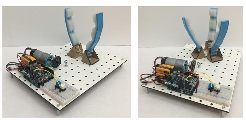
The materials for the electronic gripper cost ~ $150 and can take about two hours to construct once all the materials are gathered. In this gripper option, students can observe the connections needed to make the system work such as the Arduino, motor, switches and batteries. Created to be repositionable, the number, angle, and position of the fingers are easily altered to test various designs. Observing the SDM fingers as a part of a robotic system being controlled by microcontroller helps students understand the parts of a robot and all the various aspects that can customized for specific applications.

The manual gripper still allows for student led design decision however it calls for simple and inexpensive materials and assembly time is less than 15 minutes. This gripper allows students to experiment with the number and placement of the fingers on the handle and can be used as an intro into mechanical components of a gripper.

Electronic Gripper
Please note: we recommend that before beginning , both activities should be evaluated on a student-by-student basis to ensure the age and ability level is appropriate for the specific student population.
The electronic gripper is a simple circuit, motor and pully configuration that allows students to create a gripper that is customizable and reconfigurable to test various gripper designs. This design requires more materials and assembly than the manual gripper however, it can be completed in groups to create team challenges and save costs. The modifications that students can choose in the electronic gripper include:
- Number of fingers
- Configuration of the fingers on the pegboard
- Orientation of fingers relative to each other

Manual Gripper
This simple, DIY gripper is simple solution for building a manually actuated gripper. This version helps students combine the SDM fingers into the component of robotic arm that can be endlessly customized. This design does not include any electronics, or sophisticated hardware however, students are still able to create and test a gripper that can have various configurations.
These variations include:
- Number of fingers
- Distance between the fingers
- Orientation of the fingers relative to each other

Fabrication
The following sections include instructions for fabrication for both gripper designs. The step-by-step instructions are provided on the subsequent pages.
Electronic Gripper:
A detailed Bill of Materials is included in the Downloads page listing specific part numbers, quantity, suppliers and cost. Please note: some materials can be substituted for cheaper or more widely available version at your own discretion. Some of the materials are also called for in the SDM finger activity and can be reused used for this activity.
The Downloads link below also includes templates to build the angled cardboard stands for the fingers and the code file that will be uploaded to the Arduino microcontroller to control the circuit.
Manual Gripper:
This version of the gripper is also significantly cheaper per unit than the electronic gripper requiring only household materials such as a hollow tube (cardboard or plastic), crafts string and zip-ties.
The Bill of Materials for this version of the gripper is also located within the Downloads page.
Bill of Materials
This section will give a list of items that are used in this project with selected links to suppliers. You can download a more detailed Bill of Materials sheet here.
Note: Many of the items listed are just examples and you can use your own discretion to substitute parts which are easier or cheaper to obtain.
Materials for Electronic Gripper
Electronics
|
|
|
|
|
|
|
|
|
|


Other Materials
|
|
|
|
|
|
|
|
|
|
|
|


Materials for Manual Gripper
Required Materials
|
|
|
|


| bom_gripper_for_sdm_fingers.xlsx | 1.55 MB |
Electronic Gripper
Gather the materials labeled for the electronic gripper from the Bill of Materials page and a downloadable file located in the Downloads tab. Fabrication the electronic gripper involves the following steps:
1. Making repositionable cardboard bases for each finger (below)
2. Connecting motor and pulley to the fingers
3. Attaching electronic components to the pegboard
4. Placing and connecting fingers to integrate the mechanical and electronics
Step 1: Making repositionable cardboard bases for each finger
Print the 'FingerBaseTemplate.pdf' on letter size paper and using the paste glue, adhere the paper to cardboard.

|
Students have the option of choosing one of two varying angles for the finger base. Once this is chosen, cut out the corresponding template using scissors or a craft knife. The holes within the template can be hole punched using the punch purchased for the SDM finger activity.

|
Note: If the provided templates do not have the angle that is required for a specific design, these can be customized to increase or decrease the angles of the base.
Cut the cardboard according to the template using craft knife.

|
Fold the card board into a triangle as shown with the tabs folding out and down from the sides, as shown to make a prism. Apply glue from a gun liberally to make the base firm. Be careful not to hot glue the base to the surface you are gluing on.

|

|
Insert one of the SDM fingers as shown within the base. Secure the finger through the punched holes using two zip ties. Place a screw through the bottom of the base sticking outward to allow for attachment from the bases to the pegboard.

|

|
Once the bases are attached the finger is now ready to be placed anywhere on the pegboard with the help of the screw at the bottom. This process can be repeated for as many fingers as students would like to test.

|
Connecting motor and pulley to the fingers
Step 2: Connecting motor and pulley
Cut about 2 feet of string to thread into the pulley. Loop around the pulley once and tie a knot that will allow the string to be secured to the internal channel of the pulley.

|

|
Lace one end of the thread through the two adjacent holes in the pulley and tie a knot there as shown. This will prevent thread from slipping around the center channel of the pulley and ensure that the pulley winds as it pulls. Double knot is necessary.

|

|

|
Connect the pulley on the mounting hub using the screws and nuts provided with the motor and pulley.

|

|
Attach the aluminum bracket, the motor and the mounting hub using the screws provided. Your motor is ready to be attached to the gripper board.

|
Attaching electronic components to the pegboard
Step 3: Attaching electronic components on board
Cut the pegboard to the recommended size 12x12 inches using a craft knife or similar. This may need to be cut before beginning the activity to reduce time to complete. Attach one of each of the spacers to all four corners of the pegboard.

|

|
Using an eye hook, divide the board into roughly two halves. On one side, the electronics and the motor will be placed and on the other side, there will be space to place the fingers in various configurations.

|
Using two of the M2 screws provided, fix the motor to the peg board so that the pulley is aligned with the eye nut. This will create a routing point for the string to make sure that it correctly routes to the pulley.

|
Gather the battery, motor, Arduino and breadboard together. Using your jumper cables, resistors and push buttons create the following circuit.

|
To upload the code that programs the microcontroller, connect your Arduino to a computer. Open 'Master.ino' file in Arduino IDE. Upload 'Master.ino' to your board.

|
When upload is complete the entire circuit can be disconnected from the computer and adhere to the pegboard as shown using double sided tape.

|
Placing and connecting fingers to integrate the mechanical and electronics
Step 4: Placing and connecting fingers
Using the screws on the finger bases, attach the finger using the pegboard. The fingers can be placed anywhere on the board. Using a nut on the underside of the pegboard to adhere the screw, fasten the finger and base tightly into place. Insert eye screws within the finger configuration to channel the string back to the motor pulley.

|

|
When adding another finger do the same for the base screw and eye screw, making sure to secure both with nuts on the underside of the pegboard. Tie the threads of all fingers to the thread coming from pulley, making sure to keep this connection tight.

|
Manual Gripper
The following materials are the only supplies needed to create the manual gripper:
- A hollow tube (cardboard or plastic)
- Crafts string
- and zip ties (2)
- Download the detailed bill of material here.

|
To create different grippers to test, the following variables can be altered:
- Number of fingers
- Orientation of fingers towards each other
- Distance between the fingers (depending on availability of tubes of different diameter)
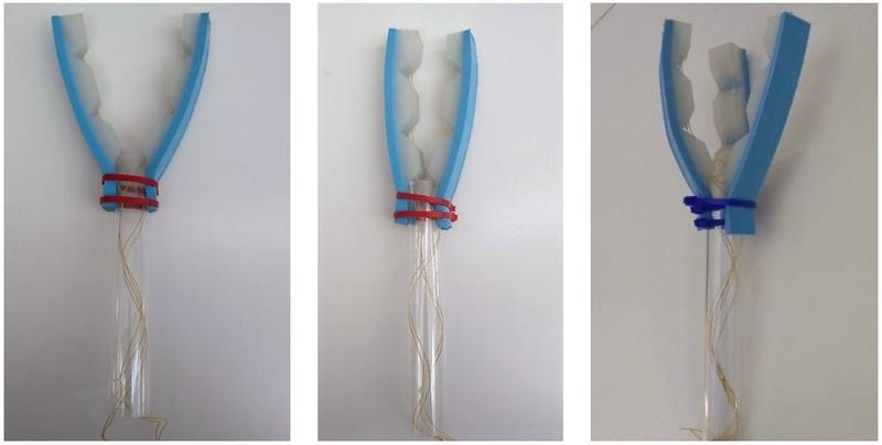
To assemble, place the laced fingers on either side of the hollow tube as shown, if using three or more fingers, you may need to pretension the zip ties before wiggling in a third and fourth finger inside the zip ties. Situate the fingers so that the natural position of the fingers is slightly angled outward, by pulling the bottom of the finger down slightly until the last segment intersects with the handle, as shown. Using the two cable ties to secure the fingers, pull taught and cut the excess zip ties.

|

|

|
Your gripper is ready!

|
Testing
Testing different grasps is essential for customizing a gripper to an object. The SDM finger activity provides students with an option to prepare two different designs of fingers. From there, this fabrication guide details the variations that can be accomplished within the electronic and manual grippers.
Problem-Based Approach
The following steps describe an overview of the problem-based approach on which this activity focuses.
Step 1: Select or assign an object
Objects can be selected or assigned to students within the activity. Typically, variations in shape, size and weight will influence the needs of the gripper designs. Students can work in groups or alone to start designing for the requirements of their particular object.
Step 2: Make a hypothesis
Before building the gripper, students should form a hypothesis regarding what would constitute a suitable grasp for the object assigned or chosen. Sketches, discussion and prototypes can also be used to help map out the best possible solution. Factors that will need to be chosen within the electronic gripper include:
- Most suitable finger design (this is an option included when building the SDM fingers)
- Number of fingers required
- Distance and orientation between the fingers
- Angle of each finger via the cardboard bases
Factors determined within the manual gripper activity:
- Most suitable finger design (this is an option included when building the SDM fingers)
- Number of fingers required
- Distance and orientation between the fingers
Step 3: Build the gripper accordingly and test the hypothesis
Students should build their grippers according to the designs they sketched, discussed or prototyped at the start of the activity. Upon testing, results should be recorded in order to make informed design modifications for the next version.
Step 4: Modify as needed according to results of step 3
Adjusting the fingers on Electronic Gripper:
The carboard finger bases that attach the fingers to the electronic control board can be easily reconfigured using the base screw and nut that secures the base to the pegboard. Simply unscrew and place in a new configuration. To ensure proper placement of the string through the pulley, make sure to use the eye screws to correctly route the string and limit tension on the finger bases.
Cardboard bases can also be changed if the angle of the finger requires alteration.
|
Adjusting the fingers on Manual Gripper
The distance between the finger can be adjusted by using tubes of different diameters. The angle between the fingers can be adjusted by moving the fingers up and down on the tube and locking the zip tie in correct position. You can add up to four fingers on the same tube of diameter 1 inch and more for larger diameter tubes.
|
Downloads
1. Bill of Materials is needed for making both the gripper design.
2. The FingerBaseTemplate is pdf file for cutting the template of movable cardboard base. This is needed for making the movable cardboard base for the electronic gripper.
3. The Master.ino file(Available in the Downloads.zip) is the Arduino program file for controlling the gripper. This file needs to be uploaded to the arduino being used in the electronic gripper.
4. Downloads.zip contains all the above files in a zipped folder.