PneuNets Bending Actuators
|
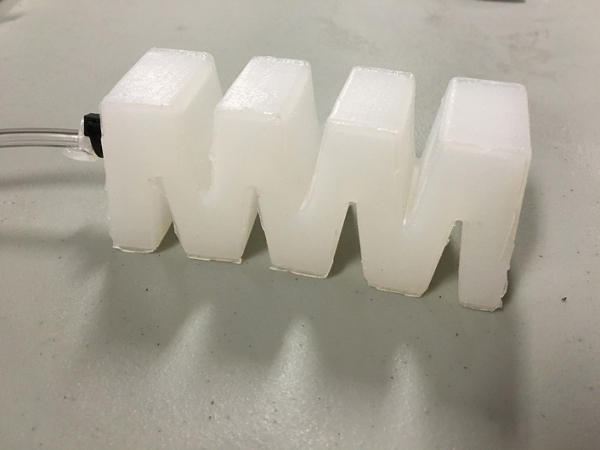
PneuNets (pneumatic networks) are a class of soft actuator originally developed by the Whitesides Research Group at Harvard. They are made up of a series of channels and chambers inside an elastomer. These channels inflate when pressurized, creating motion. The nature of this motion is controlled by modifying the geometry of the embedded chambers and the material properties of their walls. When a PneuNets actuator is pressurized, expansion occurs in the most compliant (least stiff) regions. For example, if the PneuNet is composed of a single, homogenous elastomer, most expansion will occur at the thinnest structures. Designers can pre-program the behavior of the actuator by selecting wall thicknesses that will result in a desired type of motion. |
|

|
|
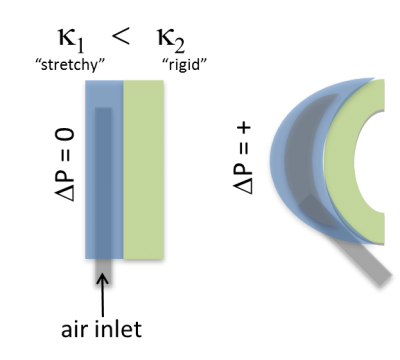
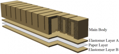
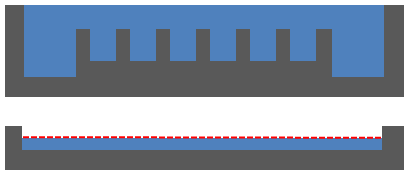
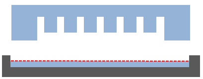
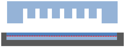
In addition, different materials can be used in combination to enable further control over actuator behavior. If a PneuNets actuator contains layers of materials with different elastic behavior (as shown in the image to the right), the "stretchy" material will expand more than the "rigid" material when the actuator is pressurized. In this type of configuration, we call the more rigid material the "strain limiting layer", as it restricts the amount of strain that can occur. The "differential strain" effect can be used to achieve useful motions such as bending and twisting. |
|
This documentation set contains files and instructions to support the design, fabrication, modeling, and testing of a specific PneuNets bending actuator. We also provide a case study of this actuator's use in an assistive glove for hand rehabilitation. While we focus on a particular example of a PneuNets actuator, the principles and guidelines presented here can be adapted to produce a wide range of actuators and devices.
| The video below shows a soft gripper made from PneuNets: |
|
|
| Shepherd et al. (2011) used PneuNets to develop a quadruped robot capable of multiple modes of locomotion: |
|
|
| Some of the information contained in this web site includes intellectual property covered by both issued and pending patent applications. It is intended solely for research, educational and scholarly purposes by not-for-profit research organizations. If you have interest in specific technologies for commercial applications, please contact us here. |
Design
|
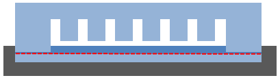
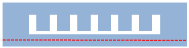
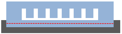
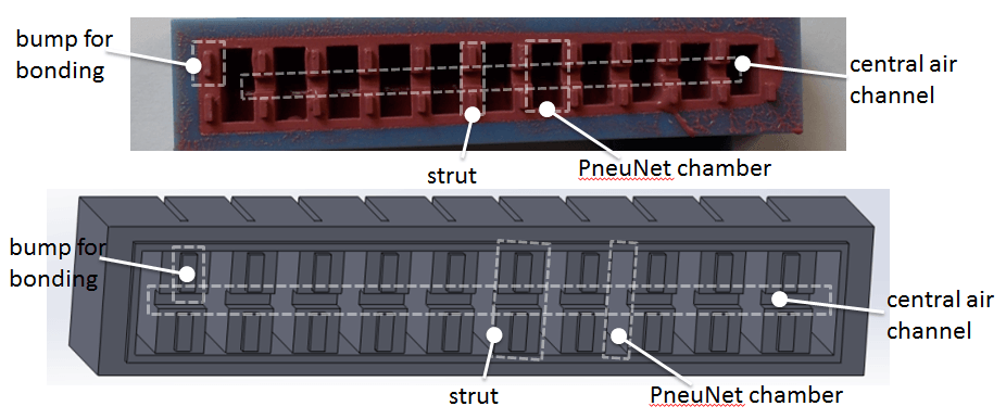
The PneuNet actuator documented here consists of a series of chambers arranged in a row, where the thinnest wall sections are those between each chamber and the next. The strain-limiting layer is a piece of paper embedded in the base. When the device is inflated, the chambers expand, and the thin walls between the chambers bulge out the most. This would cause the actuator to expand in the axial direction, but since the strain-limiting layer does not expand, the actuator bends instead. |
|
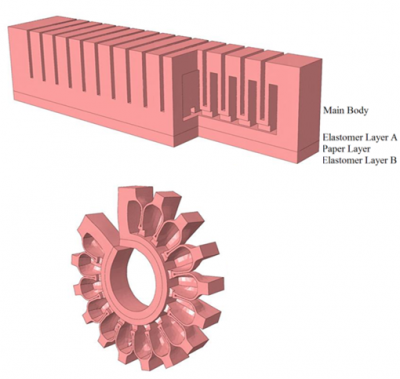
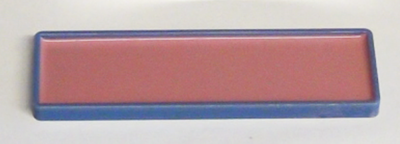
| The actuator consists of two parts: the main body, which expands when inflated, and a base containing the inextensible paper layer embedded in elastomer. |
|

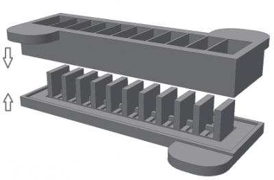
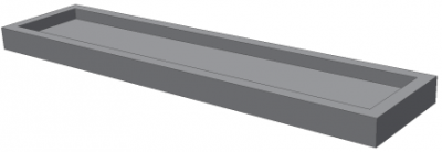
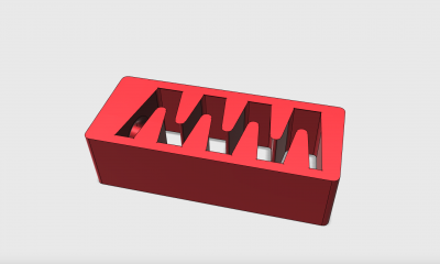
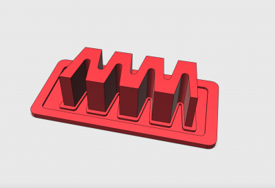
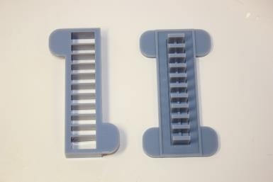
| To build this actuator, the main body and the base are cast separately and then glued together. The base of the actuator is a simple rectangular plate. The more complex main body is cast in the two-part mold shown here. |
|
The behavior of the actuator is determined by the materials from which it is made and the shape of the chambers. The next two sections provide some guidelines for selecting materials and designing the shape (or "morphology") of the actuator.
The following section contains a detailed tutorial on making solid models of the actuator and molds using SolidWorks. The resulting SolidWorks files can be downloaded here, and the .stl files for 3-D printing the molds can be downloaded here.

Variation: Material
|
Material stiffness affects how much pressure is required to make the actuator bend. High strain/low durometer (stretchy) materials will deform more for a given pressure than low strain/high durometer (rigid) materials. There is a wide variety of both types of material available. Some examples are given below. High Strain/Low Durometer:
Low Strain/High Durometer:
Changing these materials and using them in different combinations leads to varied actuator behavior. In the graphs shown (taken from Mosadegh et al. 2013), compare the pressure-volume loop of PneuNets actuators made from Ecoflex 30 & PDMS (A) with those made from Elastosil & Paper (B). Ecoflex 30 has a lower durometer than Elastosil, and as a result the Ecoflex actuator has a greater increase in volume for a lower applied pressure. |
|

Accurately predicting the effects of material selection is difficult due to the nonlinear elastic behavior of the materials and the complex shape of the actuator. The Modeling section of this documentation set contains a tutorial on using Finite Element Method (FEM) analysis to predict the behavior of the actuator. Performing this type of analysis with different materials, and performing empirical tests like those described in the Testing section, can help to guide design decisions.
When selecting a material for your actuator, the main tradeoff to consider is that lower-durometer actuators can’t apply as much force and move more slowly, but they can be operated at much lower pressures.
In the Fabrication section we describe the process for making an Elastosil & Paper PneuNets actuator; however the process will be almost identical for other materials such as Ecoflex or Dragon Skin.
Variation: Morphology
| Even without changing the material, the actuator’s behavior can be modified by adjusting its shape (morphology). For example, simply making a wall thicker will make it stiffer than a thin wall of the same material. |
|

As with material selection, predicting the behavior of a particular shape is difficult. FEM analysis and empirical testing can provide some insight, and the Modeling and Testing sections contain information on how researchers have modeled and tested these PneuNets actuators.
For example, the FEM analysis and empirical tests carried out by Polygerinos et al. (2013) yielded the following guidelines for morphology design:
|
|

Empirical tests carried out by Mosadegh et al. (2013) found that (for a fixed overall actuator length):
- Up to a certain plateau, increasing chamber height lowered the required pressure.
- Increasing the number of chambers also decreased the required pressure.
- Increasing chamber wall thickness increased the required pressure.
Mold Design CAD Tutorial
This tutorial contains step-by-step instructions for making a solid model of a PneuNets bending actuator mold in SolidWorks. The SolidWorks part files can be downloaded here. If you prefer to use a different software package, you should be able to apply the general tutorial steps to most solid modeling environments or you can refer to the dimensioned drawing below to guide you.
|
As discussed in the previous pages, this actuator consists of two parts: the main body, which expands when inflated, and an inextensible base layer composed of a piece of paper embedded in elastomer. The two parts will be cast separately and then glued together, so we will need separate molds for the main body and the base layer. |
|
|
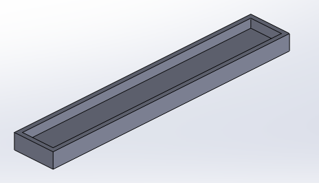
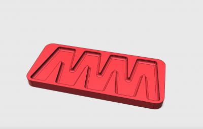
The mold for the base layer is simply a flat rectangular plate with a lip around the edges. |
|
|
The main body is more complex, and is cast in a two-part mold. The mold contains overhangs, and if we were to use a one-part mold, we would have to destroy it in order to remove the actuator once it was cast. By using a two-part mold we can reuse the same mold again and again.
|
|
|
Before making our mold we must decide its morphology (See this page for a discussion of PneuNets morphology). There are several dimensions that affect the actuator’s behavior: chamber height, sidewall thickness, spacing, and overall number of chambers.
|
|
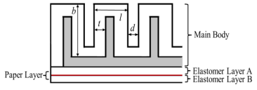
In addition, there are other dimensions to be determined: chamber width, thickness of the other chamber walls (which must be thicker than the sidewalls so that they don’t expand much in comparison), and size of the central channel.
In this tutorial we will make an actuator with 11 chambers. Each chamber is 8mm long, 15mm wide, 15mm high, has 1mm sidewall thickness, with other walls being 2mm thick, and is spaced 2mm from the next chamber. The central channel will have a 2mmx2mm cross-section. Of course, you can alter these numbers to change the morphology of your actuator and the general steps covered in the tutorial should still apply.
We will first create a solid model of the actuator, and then use this to derive the solid models for the mold pieces by following these steps:
- Encasing the actuator in a solid block
- Subtracting the actuator from the block
- Separating the resulting shape into top and bottom mold pieces
| PneuNet Molds SolidWorks Files (.zip) | 729 KB |
Design Individual Chamber
There are 2 main ways to make the actuator body: we can design a chamber and then multiply it in a linear pattern, or we can make a long rectangular solid and make several linear patterns of cuts. Here we will use the first method as it involves less arithmetic. [Video: Making a chamber unit]
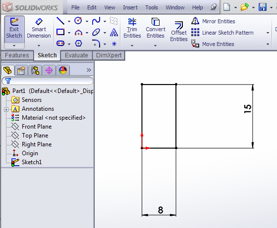
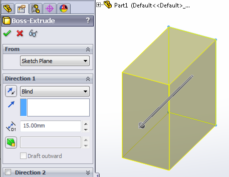
Using the Extruded Boss/Base feature, create a 8x15x15 (mm) solid block.
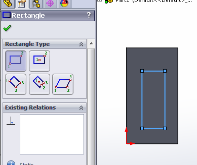
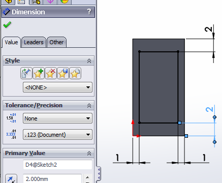
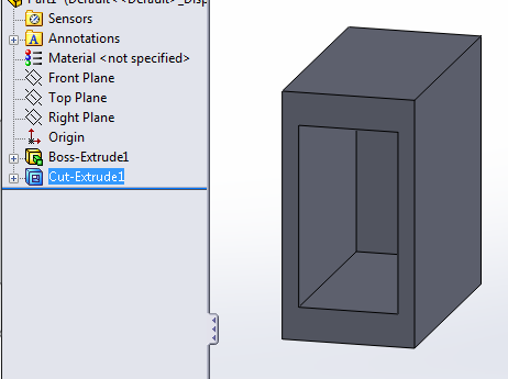
Now we need to cut out the inner cavity of the chamber. Select the Extruded Cut feature, and make a sketch of a rectangle on the bottom face of the block. Using the Smart Dimension tool, set the offset from the block edges to the appropriate wall thicknesses.
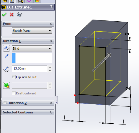
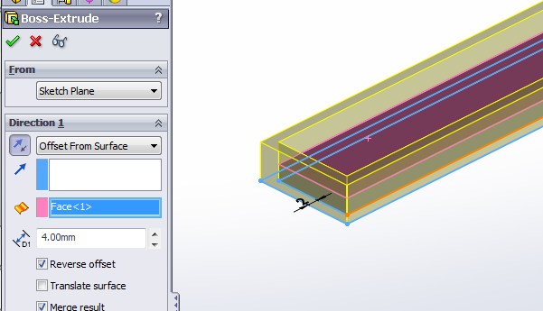
Since we want the top wall thickness to be 2mm and the block is 15mm tall, we will make the extruded cut 13mm deep. (Alternatively, instead of a Blind cut, use Offset From Surface and set it to be 2mm from the top of the block.)
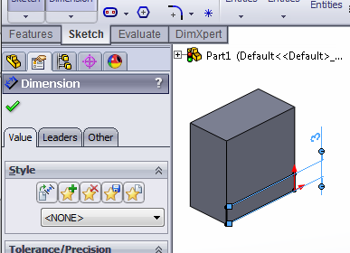
Now we need to make a strut between each chamber and the next. It will be 2mm thick, since that is our desired distance between chambers. To determine the height, we need to make sure that it is tall enough to allow room to cut out the central channel. Since the channel is 2mm tall, we will make the spacer 3mm tall.
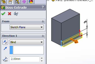
Once again, use the Extruded Boss/Base tool and extrude a spacer block from the side of the chamber.
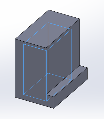
Now the chamber is complete. In the next step, we will create multiple copies of this chamber and combine them to create our actuator
Combine Chambers
Now that we have the basic chamber, we will repeat it to create row of 11 chambers using the Linear Pattern feature. Since we need to pattern the entire chamber, we use Bodies to Pattern (instead of Features) and click on the chamber that we made. [Video: Patterning chambers in a row]
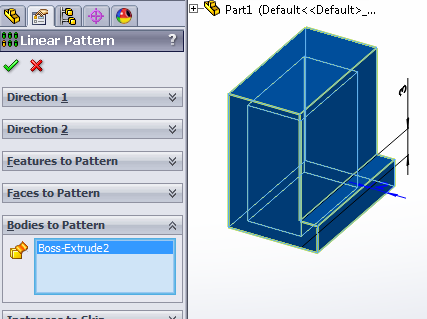
Now we select the direction to pattern the chamber. Under Direction 1, select an edge to determine the direction of patterning. You can use any edge parallel to the actuator main axis.
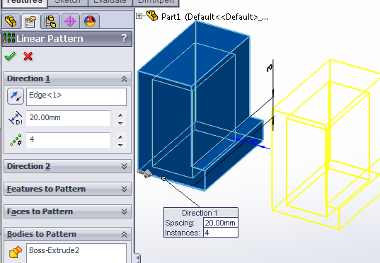
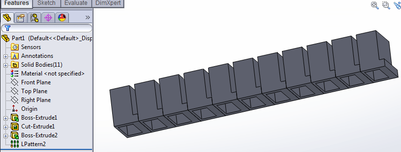
Set the distance to 10mm (8mm chamber thickness + 2mm spacer) and the pattern # to 11.
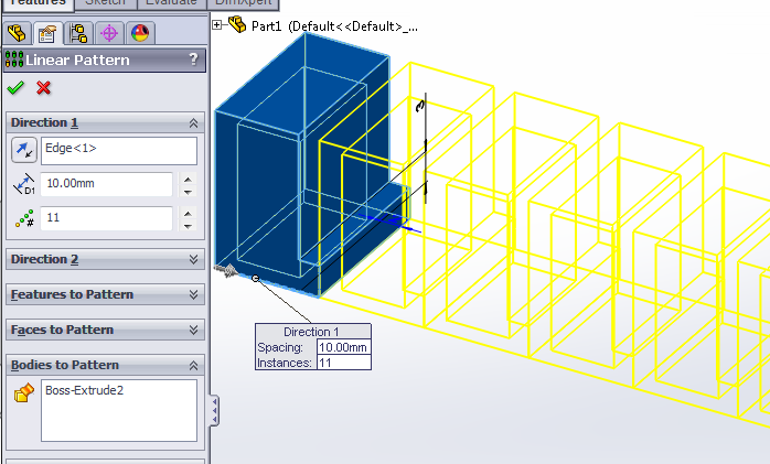
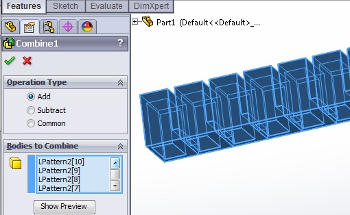
This gives us 11 separate solid bodies, which could be annoying later, so we merge them into a single solid body using the Combine feature.
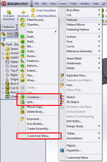
In Combine, use the Add operation type to add all the chamber bodies together. Under Bodies to Combine, select all the chambers.
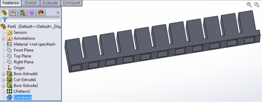
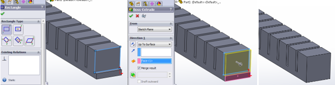
Next, we need to thicken the two ends of the actuator so that they don’t bulge out like the other sidewalls. To do this, use Extruded Boss/Base twice, to add 2mm extra thickness to each end wall. [Video: Thicken actuator ends]
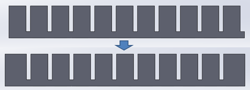
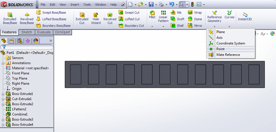
Now we cut the 2x2 mm central air channel. [Video: Cutting central air channel] To ensure that it is centered along the axis, we first need to create some reference geometry: a point that we can use to draw a centered rectangle later.
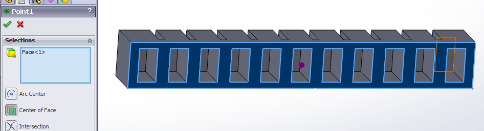
In the Point sidebar, select the “Center of Face” option, then click on the bottom face of the actuator (not inside a chamber). A dot should appear at the center.
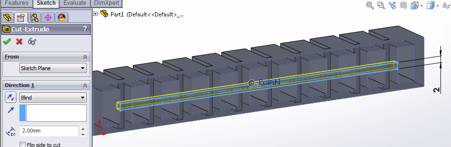
Now we use Extruded Cut to create the central channel. On the bottom face of the actuator, draw a rectangle using the reference point we just created as its center, and having its edge coincide with the inner face of one of the end chambers.
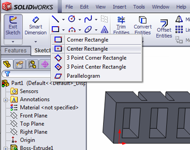
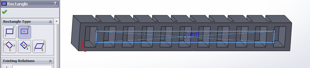
Use Smart Dimension to make the rectangle 2mm wide, then exit the sketch and make the Extruded Cut 2mm deep.
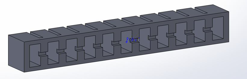
The main body of the actuator is now complete, but in the next step we will add some extra features to aid fabrication.
Add Bonding Features
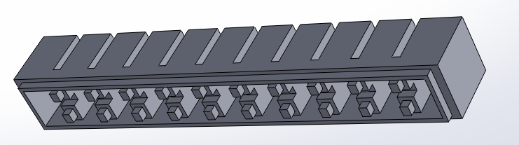
We now have the main body of our actuator. We can add some extra features to aid fabrication: when we are gluing the main body to the base layer, ridges and bumps will improve bonding between the parts by providing more surface area for the glue to adhere to. Adding some extra height to the main body also helps to prevent the glue from blocking the central air channel.
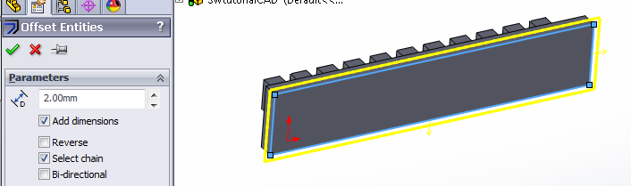
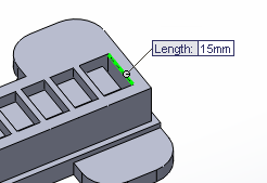
First we add a ridge around the perimeter of the bottom, using Extruded Boss/Base. On the bottom face of the actuator, draw a rectangle that encompasses all the of chambers.
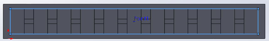
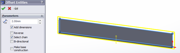
Next, while this rectangle is still highlighted, use the Offset Entities tool to create another rectangle that is offset 1mm outwards. You may have to check the “Reverse” option for the offset to go the right way.
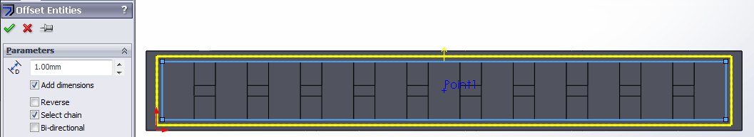
Exit the sketch and extrude the ridge 2mm.
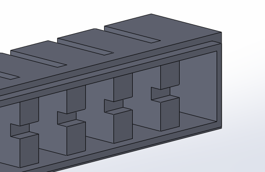
Next, we add bumps on each strut. [Video: Make bonding bumps] First we make bumps on one strut using Extrude, then we use Linear Pattern so that every strut has bumps.
On the bottom face of the actuator, select the bottom of the strut (2 separate faces because the air channel cutting through the middle), then click on Convert Entities.
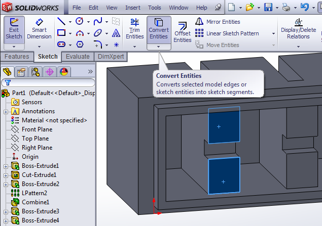
This will turn the edges of those faces into rectangles in your current sketch. Select both rectangles and mark them for construction.
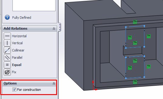
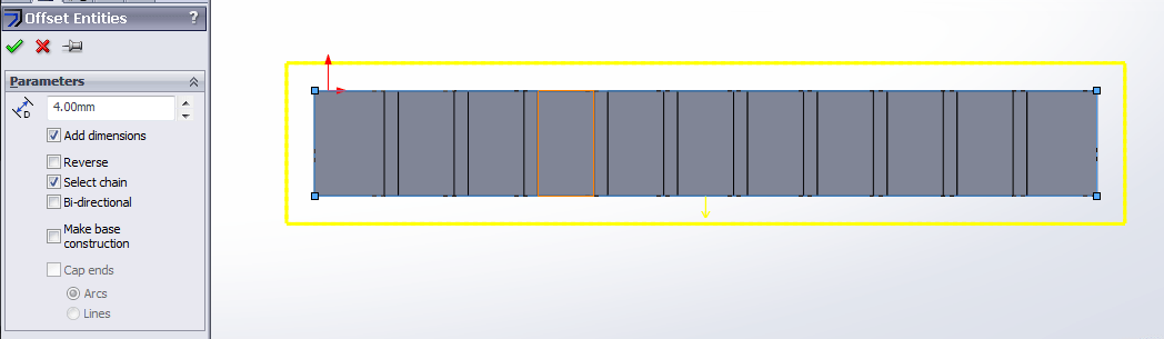
While the rectangles are highlighted, select Offset Entities again, making new rectangles that are offset 1mm inwards from the construction rectangles (you may have to select “Reverse”).
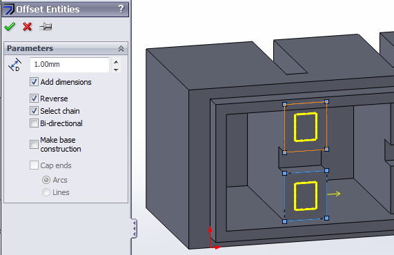
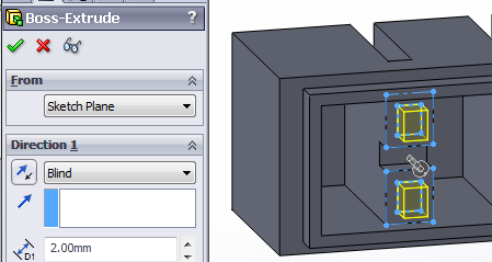
Click the checkmark to create the offset rectangles, exit the sketch, then extrude the rectangles 2mm.
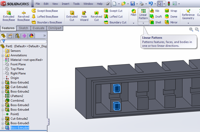
In the sidebar, select the extruded feature you just made, then click on the Linear Pattern tool.
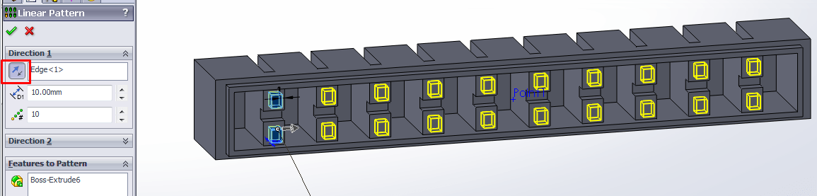
Once again, select an edge parallel to the actuator’s long axis (you may have to reverse the direction – the button highlighted in red below), and use 10mm for the pattern spacing. However, reduce the pattern number to 10, since there is 1 less strut than the total number of chambers.
Now the main body of our actuator is finished. In the next step, we will use this main body model to create our molds
Make Main Body Molds
Now that we have made a model of the main body we can use it to model the mold required to fabricate it.
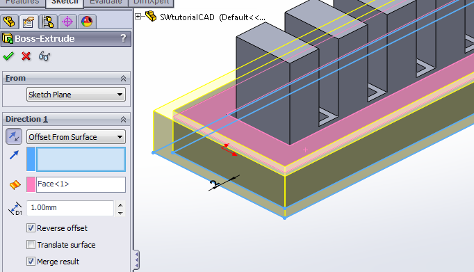
With Extrude, encase the actuator in a rectangular block, leaving about 4mm padding on every side, except for the top which should be flush with the top of the actuator. [Video: Encase actuator in mold block]
The simplest way to do this is to draw on the top side of the actuator. Make a construction rectangle that encompasses the entire face, then make a 4mm outwards offset using Offset Entities.
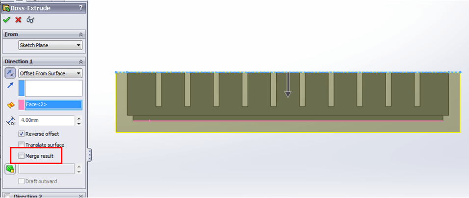
Extrude this large rectangle so that it encases the actuator, going 4mm past the bottom-most face of the actuator (the bonding ridge). You may have to reverse the direction and/or the offset. Make sure to uncheck the “Merge Result” option.
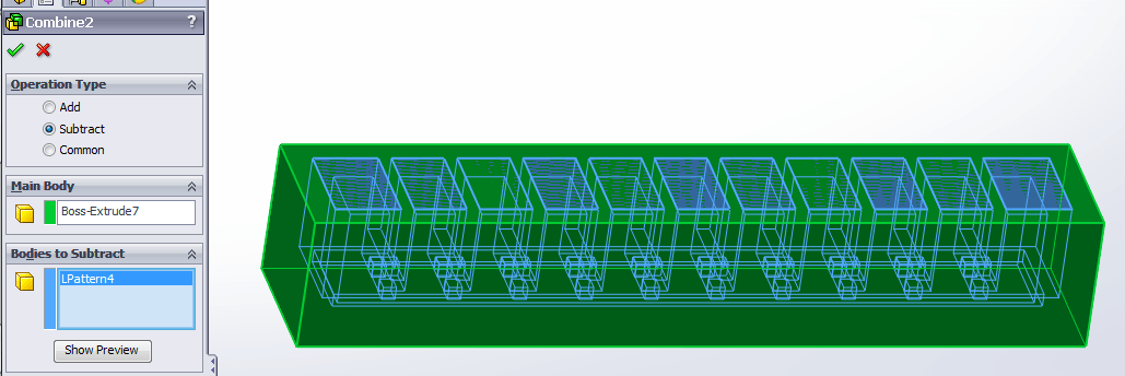
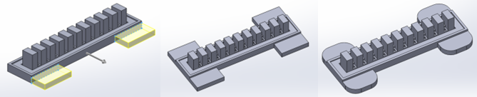
Next, we need to subtract the actuator body from the encasing block to get our mold. [Video: Subtract actuator from block] We do this by using the Combine feature again, but this time using the “Subtract” operation. Choose the encasing block as the “Main Body” and the actuator CAD model as the “Bodies to Subtract.”
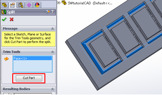
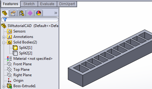
We now have a mold; however, as it is, we cannot remove the molded piece without breaking the mold. We now have to divide the mold into 2 separate pieces which can be pulled apart for demolding. To do this, use the Split feature (Insert > Features > Split). [Video: Split mold]
When using Split, the user must choose the plane along which the split occurs. Click the box under Trim Tools so that it is highlighted, then select the face for splitting.
The face we want is the one that corresponds to the bottom of the actuator, excluding the bonding ridge/bumps. Look at the mold from the top, where the holes are, and select the rectangular face closest to the outer wall of the mold. (The inner one is the depression corresponding to the bonding ridge on the bottom of the actuator.)
Once the face is selected, click the “Cut Part” button.
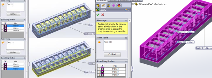
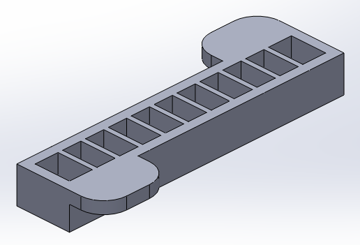
The cut will result in 3 bodies. Select the one that looks like a ladder (as in the last image) and check its box, then finalize the Split by clicking the green check mark.
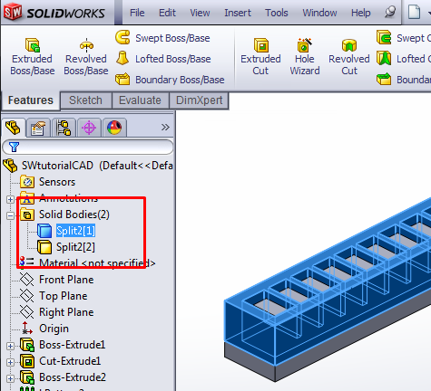
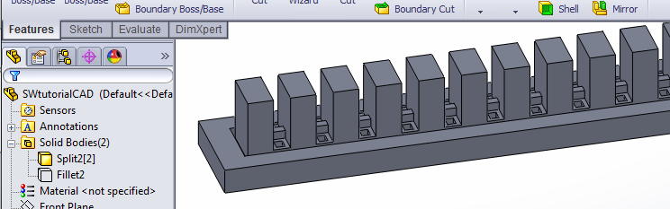
There should now be two solid bodies in this document, one corresponding to the top mold piece and one for the bottom. You should be able to see them near the top of the FeatureManager Design Tree on the side of the window.
We will edit each of these bodies to add features that make the molding process easier. First, hide the bottom body so that it doesn’t clutter the view while we edit the top part. Click on the bottom body and a small menu will appear. Click on the glasses icon to hide the body.
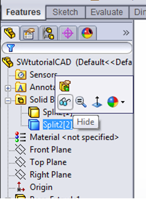
Now, only the top mold piece should be visible:
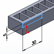
To this piece, we will add tabs on the side to provide grip when pulling the mold pieces apart. [Video: Edit top mold piece] Use Extrude and draw a rectangle in the top corner of one of the side faces. Extrude it out to create a tab. Repeat for the other side.
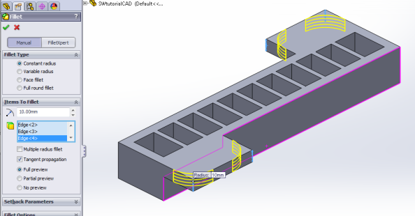
You can round out the grip tab corners so it looks nicer (though it is not necessary) by using the Fillet tool, and selecting the 4 sharp edges of the tabs.
This piece is now complete and ready for printing. Save it as an .STL file (or whatever file format your 3D printer uses): File > Save As and set “Save as type” to STL (*.stl)
Now we need to edit the other half of the mold. Hide the current body, and unhide/show the other one (using the glasses icons again). [Video: Edit bottom mold piece]
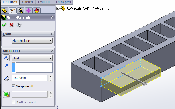
To this part we will add a raised lip around the perimeter to help align the two mold pieces.
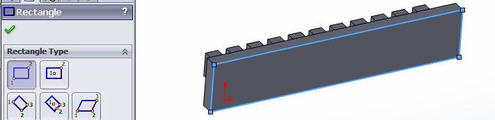
An easy way to do this is to Extrude an offset from the flat bottom face of the part. Draw a rectangle that encompasses the entire bottom face, then while it’s still highlighted, use Offset Entities to create a small outwards offset.
Once this sketch is complete, extrude it upwards, towards the top of the mold piece, so that it’s raised slightly above the mold floor, creating a lip. You may have to reverse the direction, or if you use “Offset from Surface” you may have to reverse the offset.

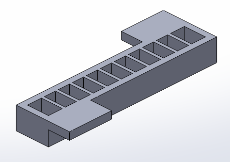
Now that the alignment lip is complete, create tabs for this piece as well, using the same method as before. Once the piece is complete, save it as another .STL file.
The molds for the main body are now complete. In the next step, we will make the mold for the base layer
Make Base Mold
Now we have to make the mold for the actuator’s base layer. This is simply a rectangle that has the same dimensions as the main actuator, with a 4mm raised lip around the edge.
Measuring our actuator (Evaluate > Measure) gives us the dimensions 112mm x 15mm.
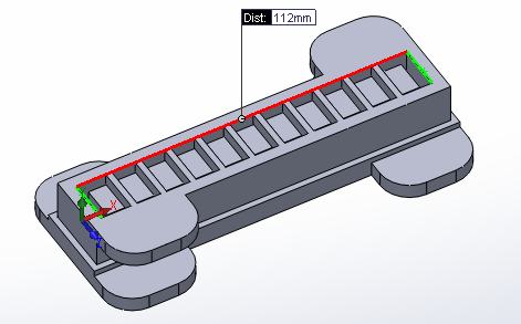
Extrude a 112mm x 15mm rectangle to 3mm thickness. Use the same method as before, with the alignment lip, to create a 4mm high lip around this mold.
The completed base mold should look like this:
Save it as a .stl file.
The mold solid models are now complete. You can use the .stl files you have created to make the molds with a 3D printer.
Variation: Geometry
PneuNets Extending Actuator
As discussed previously, changing the geometry of the basic PneuNets design can change the behavior of the actuator drastically. A variation of the PneuNets bending actuator developed independently by Aidan Leitch (a soft robotics enthusiast from New York) called a PneuNets Extending Actuator (PEA) does just that. Like the PneuNets bending actuator described in the surrounding documentation, it uses differing wall thickness and wall geometry of its internal chambers to create motion when pressurized.
Design
As opposed to bending like the original PneuNets Actuators, the geometry of the PneuNets Extending Actuator’s chambers causes it to expand axially when inflated. The PEA uses the same concept of arranging thin and thick walls in order to push against each other when inflated, but the arrangement of the internal chambers and the lack of a strain limiting layer lead to no bending of the actuator upon inflation. (Note: The actuator in the video above seems to bend because the tip is being constrained by the table).
The actuator is made of two bonded parts. The main body is first molded as an open chamber and then an elastomer layer is bonded to the opening to close and seal the chamber. Unlike the PneuNets Bending Actuator, PEAs do not use an inextensible layer (like the paper layer used in this tutorial which can be seen here). If such a paper layer was used, the actuator would not be able to extend when pressurized. A strain-limiting layer could be used if the layer was extendable, but not bendable. This would increase the actuators extending abilities as well as strengthening the actuator against buckling.
Fabrication Setup
This section provides an overview on the fabrication of the PneuNets Extending Actuator. As mentioned previously, the actuator’s design involves two parts: a main body and an elastomer layer, both of which are made of SmoothOn MoldMax 10T. The fabrication process is very similar to that of the PneuNets Bending Actuator.
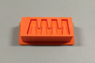
The mold consists of 3 parts, a top, a bottom and a base piece:
 |
 |
|
Top |
Bottom |
 |
|
| Base |
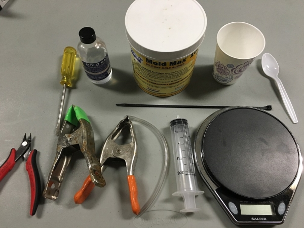
Bill of Materials
- 3D Printed Mold Parts (3 of them) (.STL files can be downloaded below)
- Smooth-On MoldMax 10T (About 140g of A and 14 g of B will be needed)
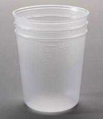
- Mixing cup
- Spoon (or similar stirring utensil)
- Scale
- Tubing (only around 4” needed, but can make as long as you want)
- Pressure source (a syringe or handheld bicycle pump will work)
- Zip-tie
- Clamps (2 needed)
- Flathead screwdriver
- Flush snips
Fabrication Guide
| Step 1: | |
 |
Place the top mold onto the bottom mold as shown. |
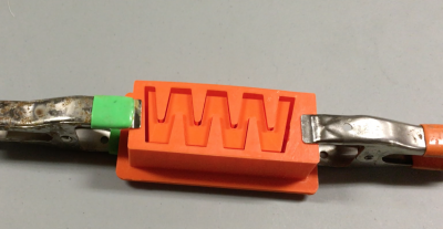 |
The two halves of the mold will snap-fit into place, but it is highly recommended that clamps are used at either side to prevent leaking. |
| Step 2: | |
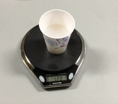 |
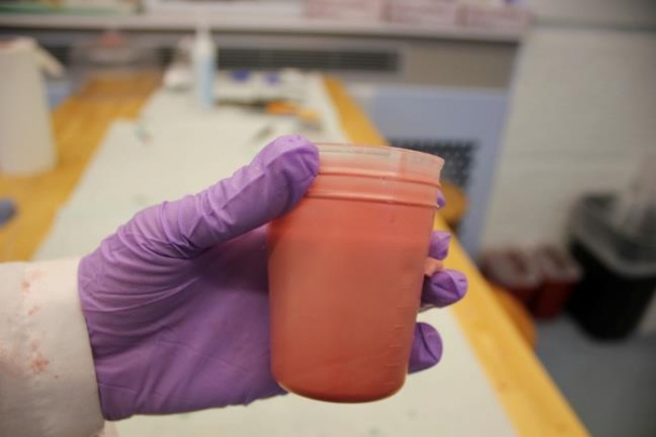
MoldMax 10T is a silicone mix that is mixed in a 10:1 ratio by weight, meaning if there is 10g of part A, there must be 1g of part B. The molds require about 130g, so first prepare 120g of part A. |
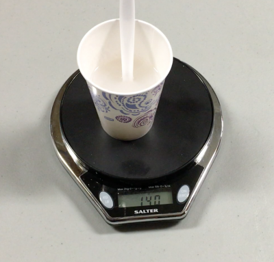 |
Next add 12g of part B. Also keep in mind the weight of your cup and spoon. In this example, the cup and spoon added 8g to the scale. |
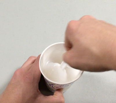 |
Use the spoon to mix the resin thoroughly. |
| Step 3: | |
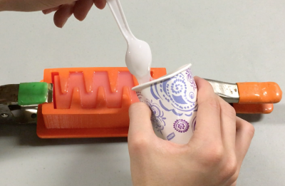 |
Pour the mixed resin into the mold slowly and consistently. Take short breaks in the pouring to let small bubbles escape. |
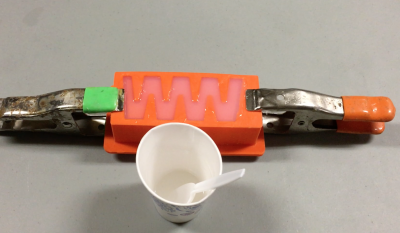 |
Once the mold is completely full, let it cure for 24 hours at room temperature. |
| Step 4: | |
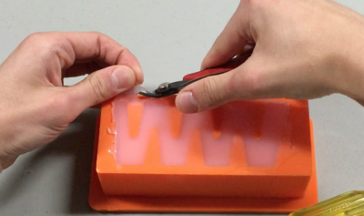 |
Once the silicone has cured, the cast can be demolded. Use flush snips to trim off any silicone at the top or edges of the mold. |
 |
Use the flathead screwdriver to pry the two halves of the mold apart. With enough leverage, the bottom mold should pop out. |
 |
Use the screwdriver to peel the cast away from the edges of the mold. |
 |
You should be able to pull the whole cast out. |
 |
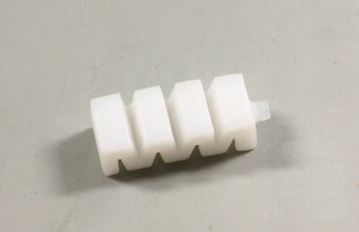
The actuator body should have one side open to the air. In the next step we will close off the chambers |
| Step 5: | |
 |
Mix up more MoldMax 10T to create the base of the actuator. You only need about 10g. |
 |
Fill the base mold to just a bit below the rim. |
 |
Place the actuator body created earlier and place it onto the base mold with the uncured silicone. Make sure the main body fits snugly into the base mold. Let the actuator cure for 24 hours at room temperature. |
| Step 6: | |
 |
Once the actuator has cured, grip it firmly on the sides and peel it up from the base mold. |
 |
| Step 7: | |
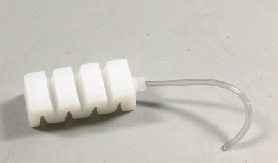 |
Insert a short length of ⅛” tubing into the sleeve of the actuator. |
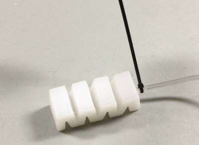 |
Tighten a zip-tie around the tubing and sleeve to prevent leaks. |
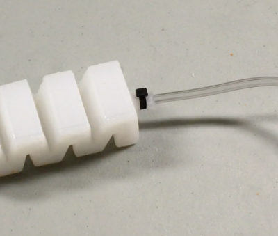 |
Check with your pressure source to make sure there are no leaks before trimming the excess zip-tie. |
 |
| A finished PneuNets Extending Actuator |
Downloads
The STLs to create the molds and the source files (done in 123D Design) are linked below.
| pea_123d.zip | 289 KB | |
| pea_stls_01.zip | 1.58 MB |
Fabrication
This section contains detailed step-by-step instructions for casting a PneuNets bending actuator. As explained in the previous sections, the PneuNets actuator consists of two parts: the main body containing the chambers that will expand when the actuator is inflated, and a bottom layer containing a strain-limiting material such as paper. The two parts are molded separately and then glued together. With the use of an oven to accelerate the curing process, the actuator parts can be cast and assembled in less than an hour. An overview of the process is provided below.
Process overview
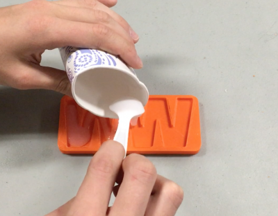
|
|
Mix elastomer and pour it into the molds. Fill the main body mold completely; fill the base mold halfway then put a piece of paper on it to serve as the strain-limiting layer. |
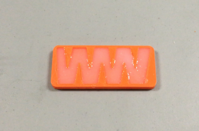
|
|
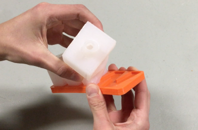
Cure both parts, and demold the main body. |
|
|
Fill the remaining half of the base mold with uncured elastomer. |
|
|
Using the uncured elastomer as glue, bond the main body piece to the base. |
|
|
Cure the two pieces together. |
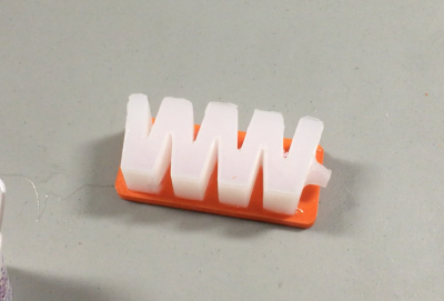
 |
Demold the final actuator. |
Bill of Materials
This section will give a list of items that are used in this project with selected links to suppliers. You can download a more detailed Bill of Materials sheet here.
Note: Many of the items listed are just examples and you can use your own discretion to substitute parts which are easier or cheaper to obtain.
Molds
|
|
| Chamber Mold (top and bottom parts) |
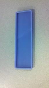
Bottom Layer Mold |
Click here to download the .stl files for these molds. You can then use a 3D printer to create the molds.
If you would like to modify the molds, click here to download the SolidWorks solid models.
Materials
|

|
|
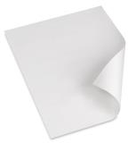
| Piece of office paper, cut to fit bottom mold |
|
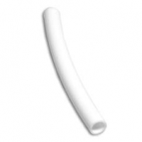
Pneumatic tubing/hose. |
*Alternative: Elastosil M4601 2-part silicone rubber* has similar material properties to Dragon Skin 30 and can be substituted here. See the Design section for a discussion of other materials options.
Tools

|
|
|
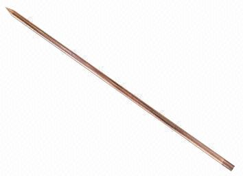
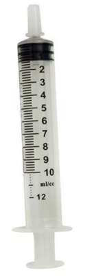
| Lab gloves | Thin (2-3mm) rod for piercing hole for tubing | Syringe (or air pump) to inflate the actuator |
Equipment
|
|
|
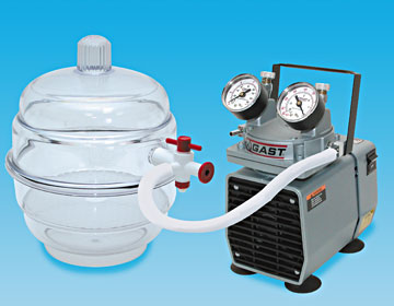
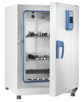
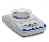
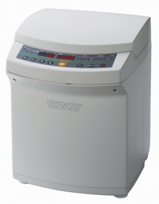
| Vacuum chamber | Lab oven (set to 65°C) | Mass scale |
|
|
|
| Mixing cups | Centrifugal mixer |
| PneuNet Molds .STL Files (.zip) | 27 KB | |
| PneuNet Molds SolidWorks Files (.zip) | 729 KB | |
| bom_pneunet.xlsx | 10 KB |
Step 1: Prepare Elastomer
Measure
Elastosil needs to be mixed in a 1:9 ratio (by weight) of Part A:Part B. In this example, we will prepare a total of 80g of Elastosil. For these molds, you will probably not need the full 80g; anywhere between 50g and 80g should be fine.
(Note: if you are using a different material, see the manufacturer instructions regarding the mixing ratio and adjust the following instructions accordingly)
Take the bottle of Elastosil Part A (red fluid) and shake vigorously. Measure out 8g in the cup, pouring slowly so you don’t overshoot. If you do overshoot, pour some back into the bottle or add more part B later to compensate and maintain the 1:9 ratio. |
|
Now add 72 g (8 g x 9) Elastosil Part B (white). Being accurate within 2-3 grams is okay. If you pour too much, you can remove some material with a spatula. This should give you 80 g total material in the cup. |
Mix
|
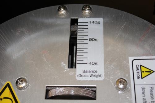
Open the mixer and remove the cupholder/adapter. Weigh the combined cupholder+cup+elastomer assembly and adjust the mixer balance to match this weight, by spinning the dial. Place the cup in the mixer and run the mixing program. |
|
Remove the cup from the mixer and adapter. If the cup is stuck, you can pry it out with a screwdriver. The material should not have any streaks; if there are, mix again. |
Step 2: Pour Elastomer
Pouring
|
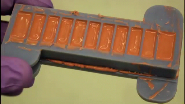
Slowly pour mixture into the main chamber mold, making sure that each chamber fills up. |
|
Fill the base mold to half of its depth with Elastosil, tilting the mold until it is evenly spread out. |
De-gas
|
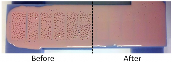
Place molds in vacuum chamber, turn on the pump, and degas for 10 minutes or until the formation of new bubbles slows down. When removing the molds, make sure to let air back into the chamber gradually by, only partially opening the valve at first. If you open it all at once, the sudden flow of air into the chamber can flip your molds over. |
Pop bubbles
|
Use the tip of a spatula to pop the bubbles that have been drawn to the surface – this is mainly for cosmetic reasons, as unpopped bubbles may cure and show up in the final product. |
|
 |
Do not go deep into the mold or pop too fast, as this can just create more bubbles – just move the spatula back and forth on the surface. You don’t need to get every single bubble, just the large ones. |
Remove excess Elastosil
|
Using a straightedge (even a piece of cut cardboard) wipe off excess elastomer. |
|
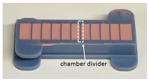 |
Make sure that the tops of the chamber dividers are still visible. This is to ensure that the chambers remain separate in the final cured piece. |
Add base paper layer
|
Pop any bubbles in the base mold and add the piece of paper on top of the Elastosil. Press the paper gently so it sticks, but not so hard that it gets submerged. |
Cure
|
Place the molds in the oven at 65°C for 10 minutes. |
Top off mold
|
Check if the level of Elastosil in the chamber mold has dropped (i.e. if the mold has leaked). If it hasn’t, return it to the oven for 10 more minutes to finish curing. If it has dropped significantly (for this design, more than 2 mm), it needs to be topped off so that the top walls of the chambers are not too thin. Pour on extra Elastosil, clean off excess with a spatula (or use your fingers), and return it to the oven. |
Step 3: Assemble Actuator
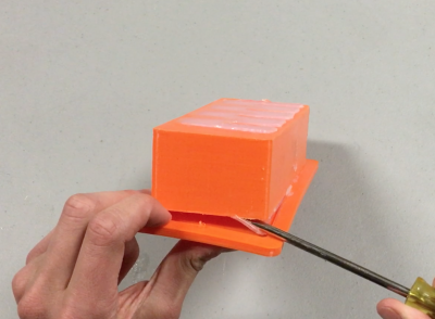
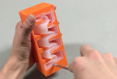
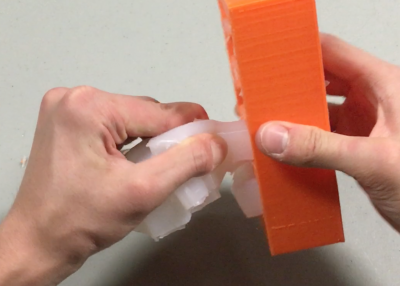
Remove main body from molds
|
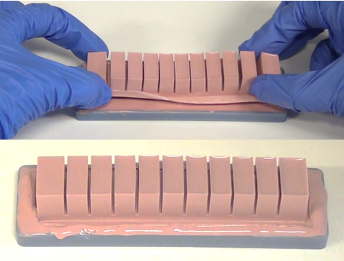
Using a flathead screwdriver, pry one end of the molds apart, then work your way around each side. Be careful not to pierce the actuator with the screwdriver. Next, use the tabs on the sides of the molds to pull the mold pieces apart. It is okay to pull very hard, as this material is hyperelastic and can stretch quite significantly before tearing. |
The mold will probably deform during this process; that is not a problem. It can be fixed by placing the empty mold back in the oven for about 10 minutes so the plastic softens, and then taking it out and putting it on a flat surface with a weight on top of it.
Join main body and base
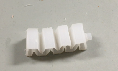
Examine the bottom of the main body/chamber piece. It should look something like this:
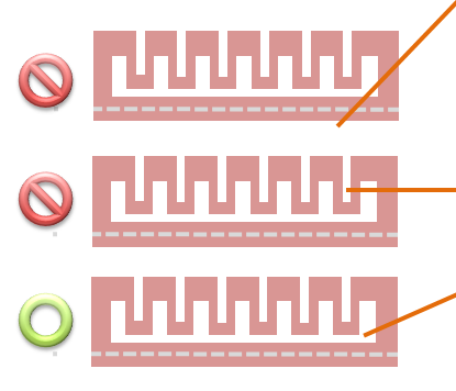
In addition to each of the chambers, there is a shallow groove running down the long axis of the actuator. This is the channel that supplies air to each the chambers. It is important not to block this channel when gluing the two parts of the actuator together, otherwise the chambers will be cut off from the air supply and the actuator will not function.
At the same time, however, the bond between the top and bottom pieces of the actuator needs to be complete so that the chambers do not leak. This means that the edges and struts of the actuator all need to be slightly submerged into the base piece before curing. The little bumps sticking out of the bottom of the top piece should be embedded into the base piece as well, further helping bonding.
|
|
Remove the base from the oven and fill the remaining half of the base mold so that the Elastosil is almost at the brim. As the Elastosil in the cup may have started curing by this point so that it is no longer pourable, you can use a spatula or other tool to scoop and spread it into the mold. If the material in the cup has become too viscous, make a fresh mixture. You will only need about 10g. Place the top piece of the actuator on the base so that it settles into the uncured Elastosil, and press down gently. If you press too hard, the central channel of the actuator may become blocked. Make sure to press down around the edges as well to ensure a good seal. Place the joined parts back into the oven to cure for 5-10 minutes. |
Inspect
|
|
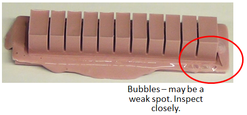
Remove the cured actuator from the oven, and peel it from the mold. Look it over and make sure there are no holes or thin spots. If necessary, patch with extra material and cure again. |
Step 4: Connect Air Source
Make hole for tubing
Using a thin metal rod, pierce the end of the actuator, an equal distance from both sides and about 1/8” (3mm) from the bottom. Aim the rod slightly downwards and don’t push it in too far. The goal is to reach the central channel without puncturing any of the actuator’s walls.
Insert tubing
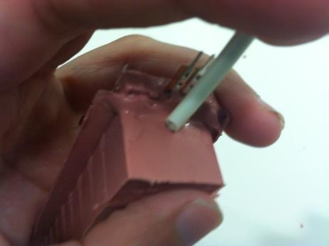
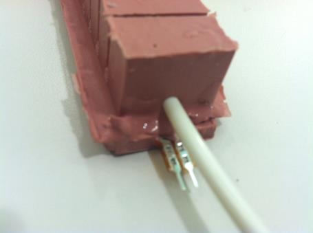
Take a piece of tubing and put it over the thin metal rod to reinforce it, then push it into the actuator through the hole you just made. Once the tubing is secure, remove the metal rod.
Actuate
Attach a bike pump, syringe, or other air source to the end of the tubing, and inflate the actuator to make it bend.
Find leaks & repair
If your actuator does not inflate you've either blocked the main air channel (in which case there's nothing you can do), or you have a leak. If you can't find the leak source, submerge the entire actuator under water, inflate, and watch for where the bubbles come out. To plug leaks, cover the hole with some extra mixed elastomer and put inside the oven to cure.
If it seems like something has gone wrong and your actuator will not inflate, it may be instructive to dissect it and try to find the problem. The silicone can easily be cut using a scalpel.
Modeling
This section describes how to perform Finite Element Method (FEM) analysis of our PneuNet actuator using the Abaqus software suite. FEM allows us to model the behavior of the actuator and see the effects of changing various parameters such as material stiffness or chamber dimensions, without needing to refabricate and retest the actuator every time a design parameter is changed.
The Abaqus input file created in this tutorial can be downloaded here and the .STEP files of the actuator can be downloaded here.
Overview of model components
- A Fluid-Structure Interaction (FSI) problem treated with a standard/implicit FEM using Abaqus/CAE (SIMULIA, Dassault Systèmes)
- 2 materials:
- Elastosil M4601 silicone rubber: Yeoh strain energy potential defined by the coefficients C10 = 0.11, C20 = 0.02. Density of 1130 Kg/m³, assumed isotropic
- Paper: density of 750 Kg/m³, a Young’s Modulus of 6.5 GPa and a Poisson’s ratio of 0.2
- 2 sections:
- Elastosil (uniform solid), assigned to the main body and 2 bottom layers
- Paper (uniform shell), assigned to inextensible layer
- 2 loads:
- Gravity, with boundary condition as 1 end rigidly fixed (encastre)
- Pressure, acting at all internal faces of the actuator cavity
- Contact interaction between adjacent chamber walls
Overview of FEM steps
- Import parts
- Make surface placeholder for paper layer
- Assign material properties to the parts (create materials, assign materials to sections, assign sections to parts)
- Assemble parts
- Model paper layer as a skin and assign final section
- Create a surface on inner cavity faces
- Apply loads (gravity, and pressure on inner cavity) and set boundary conditions
- Add contact interaction
- Create mesh and run job
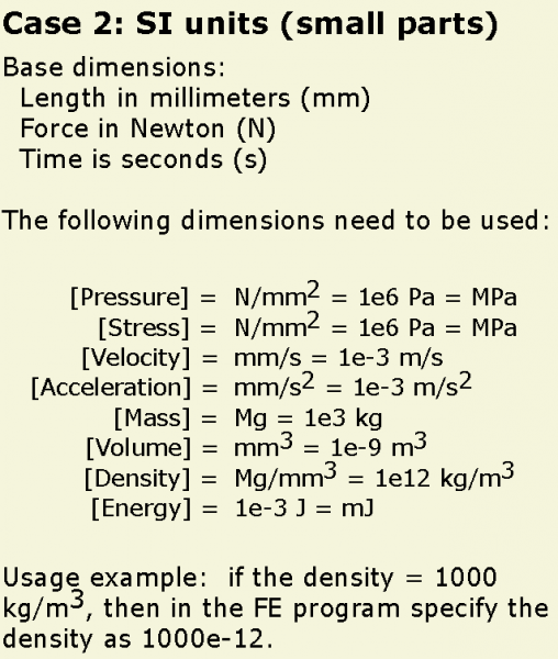
A note on units
Abaqus doesn’t interpret units so it is up to the user to make sure they are consistent. In this tutorial we use the following scheme:
| PneuNets Abaqus CAE input file | 2.73 MB | |
| Modified for Abaqus - PneuNet Molds .STEP Files (.zip) | 40 KB |
Create parts and assign materials
Import parts
[Video: Import parts and make paper surface]
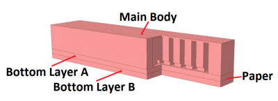 |
The generic design of these actuators consists of two different materials; the elastomer parts and an elastomer embedded inextensible part (layer of paper) at the bottom of the actuator. This layer causes the actuator to bend as it minimizes axial expansion. |
In order to make the simulation less computationally expensive, the actuator geometry is simplified by omitting certain features – i.e. the bonding ridges/bumps at the bottom the main body.
The .STEP files of the actuator geometry used in this tutorial can be downloaded here. If you would like to modify/customize the geometry, the SolidWorks part files of the simplified actuator can be downloaded here.
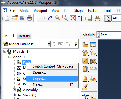 |
Import your CAD parts (as .STEP files) – here we have 3 parts, the Main Body plus Bottom Layers A & B. To do this, go to the model tree in the left sidebar, right-click on "Parts" and select Import. Browse to the .STEP file. |
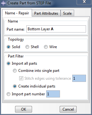 |
Name the part, and make sure to import it as a Solid. |
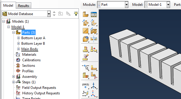
Repeat with the remaining 2 parts. All the parts should now appear in the model tree.
Create a placeholder for the inextensible layer
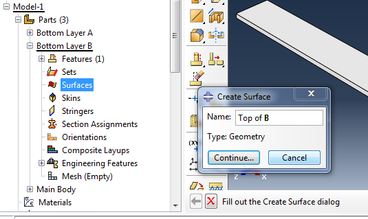
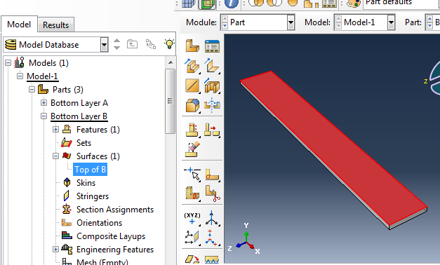
To model the piece of paper, return to the part list in the model tree and expand 'Bottom Layer B.' Double click on Surfaces and select the upper face of the part to create a surface there.
  |
Create material: paper
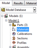 |
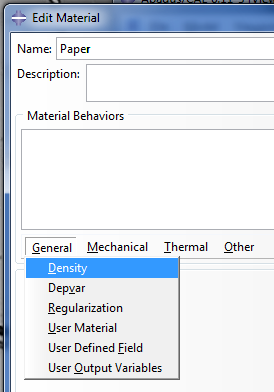
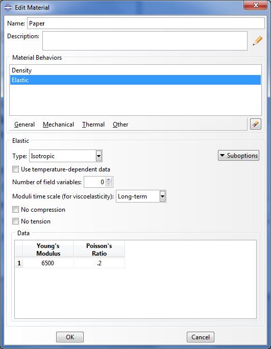
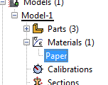
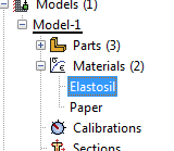
Before assigning material properties, we first create the necessary materials. We need two materials: paper, and the elastomer (Elastosil). In the model tree, double click on Materials to create a new material, and name it ‘Paper.’ |
Set the following properties:
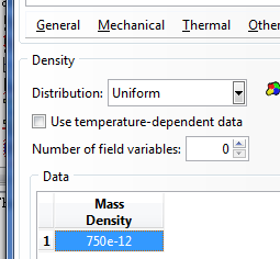
- General > Density:
- Density = 750 Kg/m³ → 750e-12 (Mg/mm³)
- Mechanical > Elasticity> Elastic:
- Young’s Modulus = 6.5 GPa → 6500 (MPa)
- Poisson’s ratio = 0.2
  |
Paper should now appear under Materials in the model tree.
Create material: Elastosil
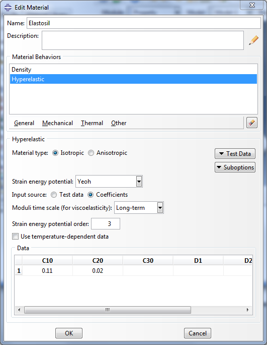
For the Elastosil, set:
- General > Density:
- Density = 1130 Kg/m³ → 1130e-12 (Mg/mm³)
- Mechanical > Elasticity > Hyperelastic:
- Strain energy potential = Yeoh
- Input source = Coefficients
- C10 = 0.11, C20 = 0.02
- Assume isotropic material type
Create sections
[Video: Create and assign sections]
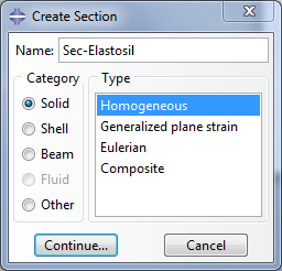
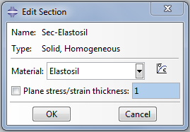
Double click on Sections in the model tree to create a new section. Set it to be a homogeneous solid and assign Elastosil as the material.
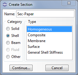
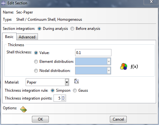
Create another section, a homogeneous shell with paper assigned as the material. Set the shell thickness to 0.1
  |
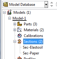
You should now have 2 sections in your model tree.
Assign sections to parts
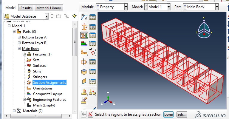
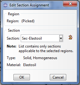
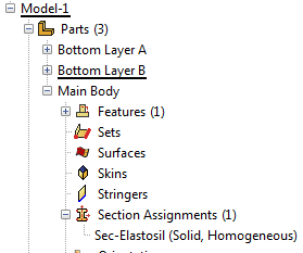
Go back to the parts you imported and assign a section to each one. To do this, look under each part in the model tree and double click on Section Assignments. Select the entire part geometry, then assign the Elastosil section.
| Modified for Abaqus - PneuNet Molds .STEP Files (.zip) | 40 KB | |
| Modified for Abaqus - PneuNet Molds SolidWorks Files (.zip) | 257 KB |
Assemble and merge
Create assembly
[Video: Assemble with constraints]
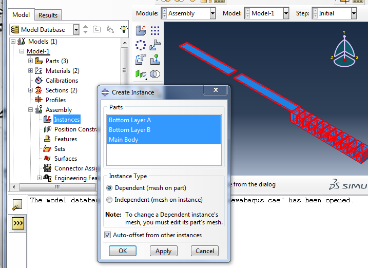
Now we assemble all the individual parts. In the model tree, expand Assembly, double click on Instances and select all 3 parts. Instance Type should be set to "Dependent".
Checking “Auto-offset from other instances” is also helpful as Bottom Layer A & B have identical shapes and positions and overlap each other, making them hard to distinguish. Alternatively, you can manually translate one of the overlapping parts.
Position parts
Now the parts have to be positioned properly relative to each other. To do this 6 total constraints are needed: 3 translational DOF for each of 2 parts, relative to one fixed part.
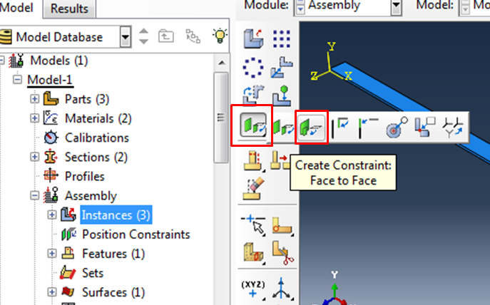
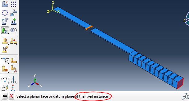
Use the face-to-face tool to “mate” faces like you would in SolidWorks (hold down the parallel faces button until another menu appears).
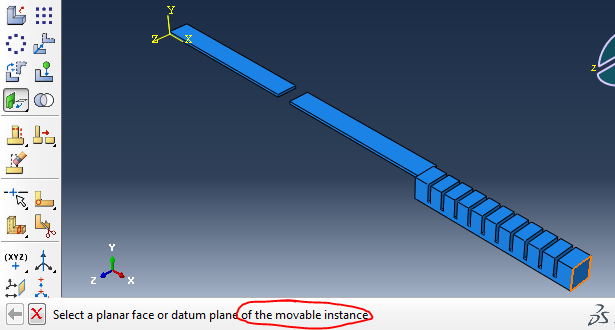
With this tool, you select the two faces you want to mate. the order in which you select faces is important: one of the parts is designated as movable, and the other as fixed. As you add more constraints, you should be consistent about the part you choose to be fixed, otherwise you will create a dependency cycle and get an error.
Here we will treat Bottom Layer A as fixed, and move the other parts relative to it.
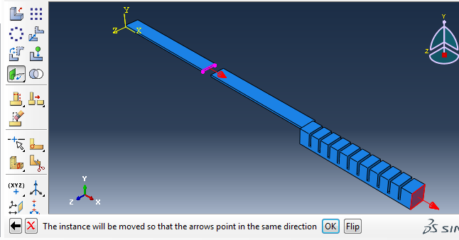
The 2 arrows that appear should be pointing in the same direction (click on “Flip” if they aren’t).
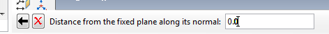
Next, set ‘Distance from the fixed plane along its normal’ to 0 and hit Enter. This completes the constraint and the movable part has changed its position.
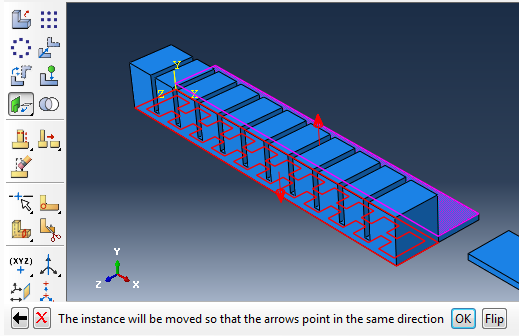
When mating the bottom face of the Main Body to the top face of Layer A, the arrows will initially point in opposite directions. Click the Flip button to make them point in the same direction.

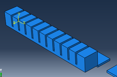
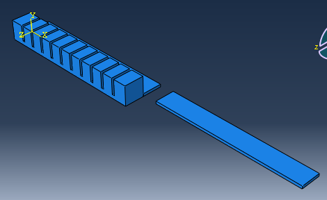
Repeat until all parts are in place.
Merge
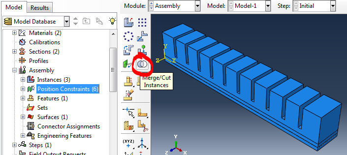
Under the assembly module toolbar, click the Merge/Cut Instances button.
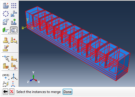 |
Select the entire assembly, and click Done. |
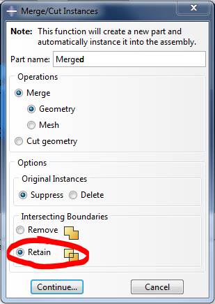 |
In the new window, make sure to use the ‘Retain’ option for intersecting boundaries. A new part, the merged part, will be created in the parts list. |
Create inextensible layer
Select surface to skin
[Video: Create skin and assign paper section]
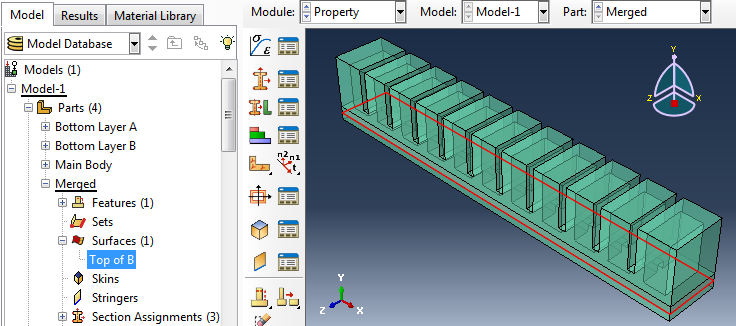
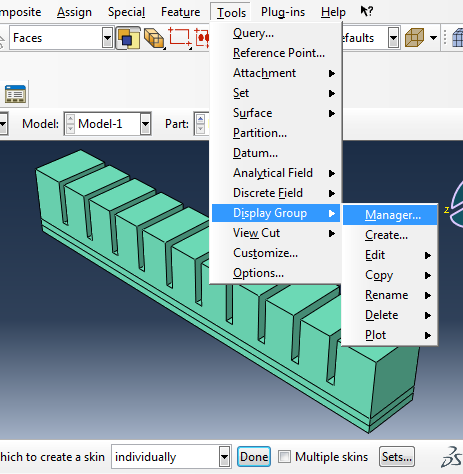
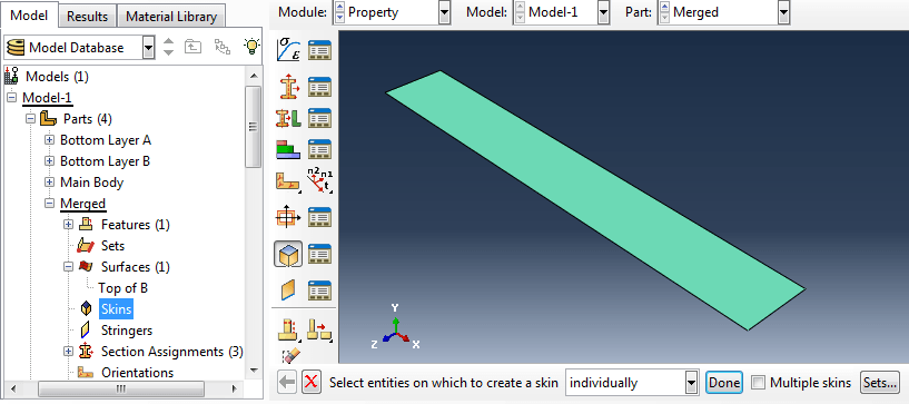
We also need to finish modeling the inextensible paper layer. Go back to the merged part and click to create a Skin. The software will ask you to select the entity on which it will create the skin. We want to select the surface of the ‘Bottom Layer B’ that we created beforehand, but right now it is buried under other parts. To isolate it, you will have to go to: Tools → Display Group → Manager.
The ‘Part Display Group Manager’ will appear – select Create.
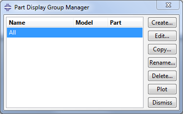
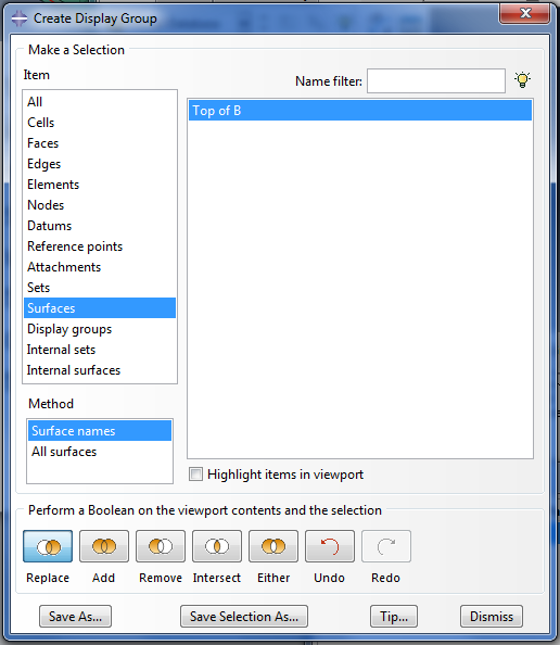
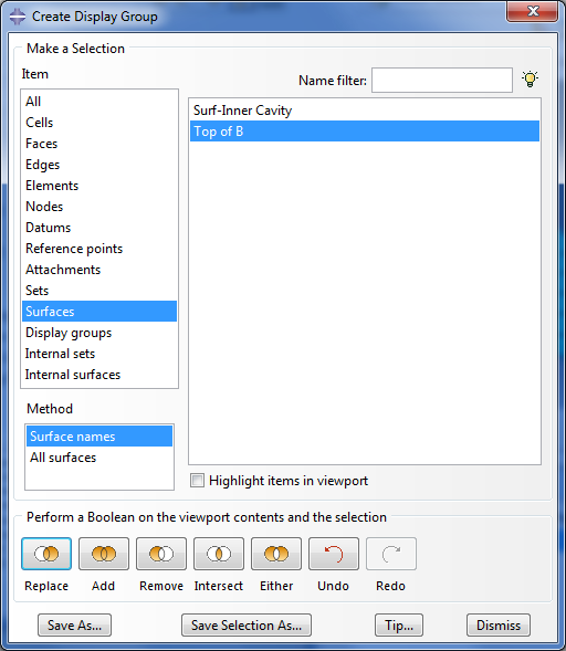
The ‘Create Display Group’ will now come up – select ‘Surfaces’ and click on the paper surface from the list and then ‘Replace’ and ‘Dismiss’.
This will make only this surface visible in the view. Select the top face of the surface to create the skin.
Assign section
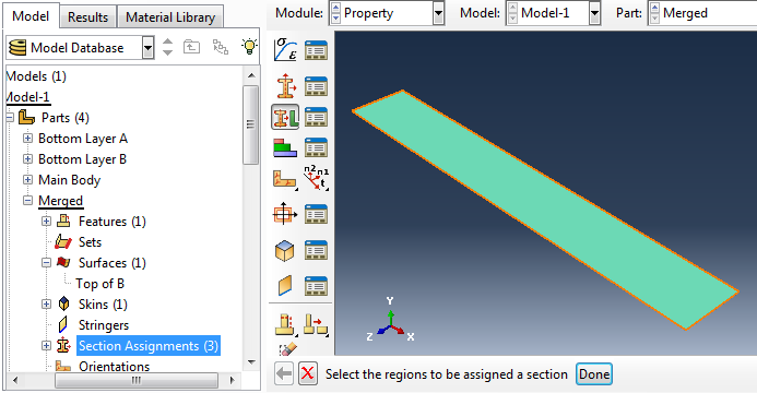
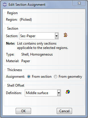
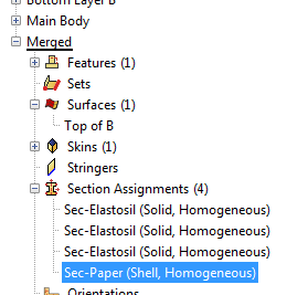
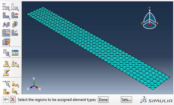
While at the Merged part, click on the ‘Section Assignment’. There you should already have three sections (all Elastosil). To create a new section for the paper double click the ‘Section Assignment’ and then select the region to be assigned a property by clicking again on the top surface. The ‘Edit Section Assignment’ window will appear where you should select the Paper as the Section. Make sure the Type is ‘Shell, Homogeneous’. Click OK. You have successfully created one more section assignment for the paper.
Create loads
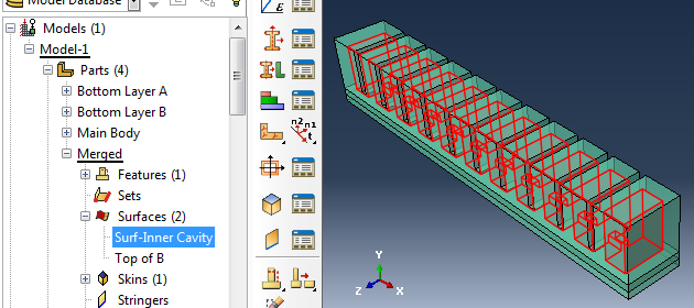
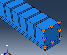
Select the inner cavity surface
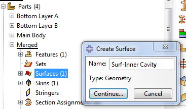 |
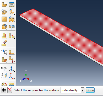
[Video: Select inner cavity surface] Before we start adding loads, we need to define the surface that the pressure load will act upon. This surface is made up of all the faces of the inner cavity of the actuator. To create this surface, expand the Merged part in the model tree and double-click on Surfaces. Name it something like “Surf-Inner Cavity.” |
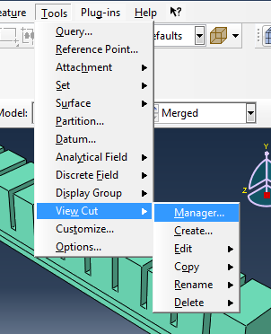
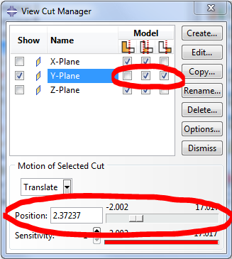
Now we have to select the faces that make up this surface. However, since the cavity is not accessible, use the Cross Section views provided from Tools > View Cut > Manager. Section using the Y-plane to expose it.
|
|
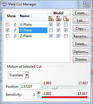
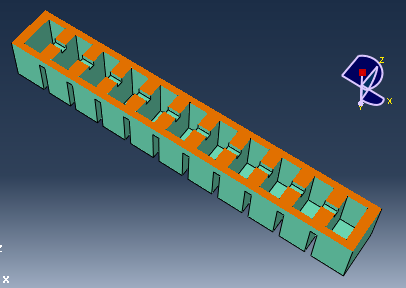
Reposition the cut until both the inner chambers and the central channel are exposed, and flip the cut so that the ceilings of the chambers are visible.
|
|
 |
Holding down SHIFT, click to select all the available faces of the inner cavity. This includes 4 sidewalls + ceiling for each chamber and 3 faces of each channel. You will have to rotate your view at least twice to be able to select everything. |
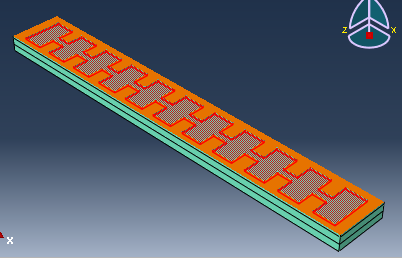 |
Finally, reverse the view cut and select the floor of the inner cavity. This completes the surface. |
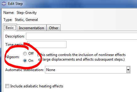
Create gravity step
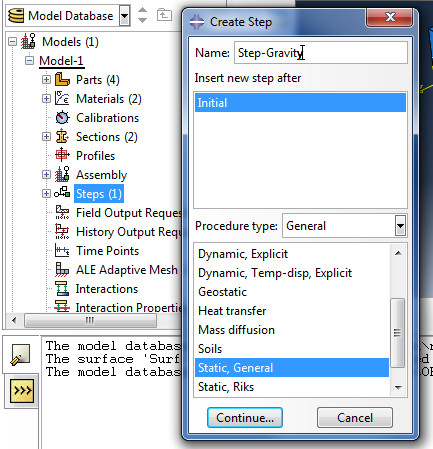 |
In the model tree, double-click on Steps to create the first step that accounts for the gravity acting on the actuator. Select a ‘Static, General’ procedure type and in the next window turn ON the ‘Nlgeom’ option. |
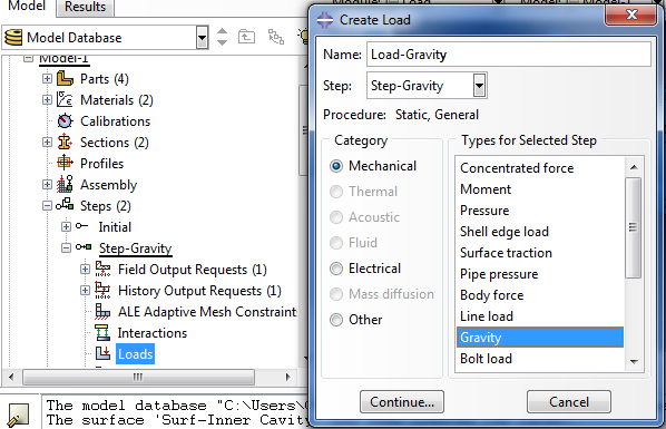
Set gravity load
Under the gravity step, double-click Loads and activate Gravity as the selected type for the step.
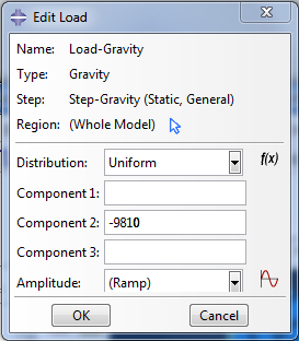 |
Set the gravity value, as -9810 on the Y axis/Component 2. |
Set gravity load boundary conditions
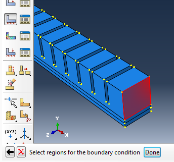
Click on BCs (boundary conditions), and select Symmetry/Antisymmetry/Encastre.
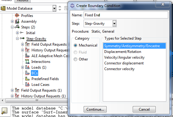
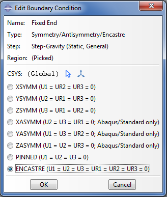
Continue and click on the face of the part that is going to be fixed. Select ‘Encastre’ to fix the surface.
Create pressure step
Create a second step by double-clicking on Step again, making it ‘Static, general’ again.
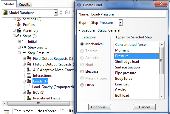
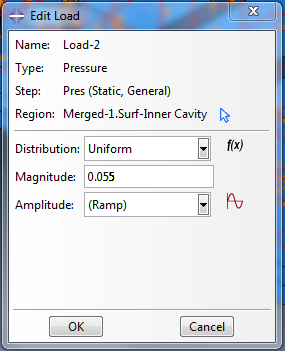
This step will have all the attributes of the previous step propagated to it and the pressure inside the cavity of the actuator will be enabled here. Within the second step, create a Pressure load.
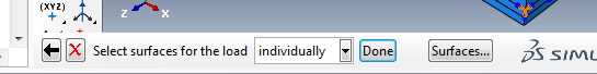
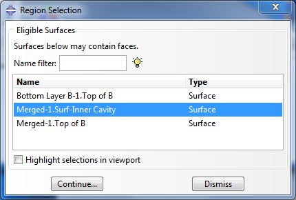
To pick the internal cavity click the ‘Surfaces’ button at the bottom right corner. In the Region Selection window that appears, select the surface "Surf-Inner Cavity" which we created earlier.
At the next window provide the pressure value to be applied in the cavity. This PneuNet design curls fully with 8 psi, which is approximately 55 kPa. Since our units should be in MPa, we use 0.055 MPa.
Add contact interaction
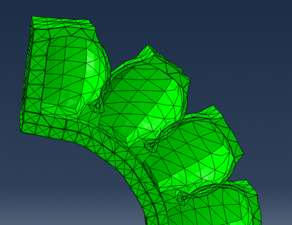
When a PneuNet is sufficiently inflated, the walls of adjacent chambers will come into contact with each other. However, Abaqus explicitly needs to be told to take this physical interaction into account; otherwise, the modeled result will have the walls simply passing through each other, as seen below:
Create interaction property
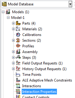
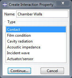
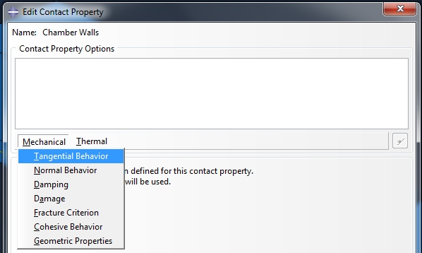
First, we create the type of interaction we want to model. In the model tree, double click on Interaction Properties and create a new property of the type "Contact."
  |
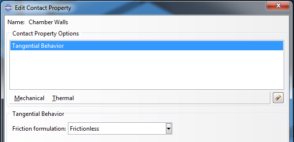
Add Mechanical > Tangential Behavior from the dropdown menu, and make it frictionless.
Create interaction
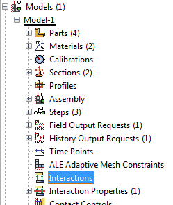
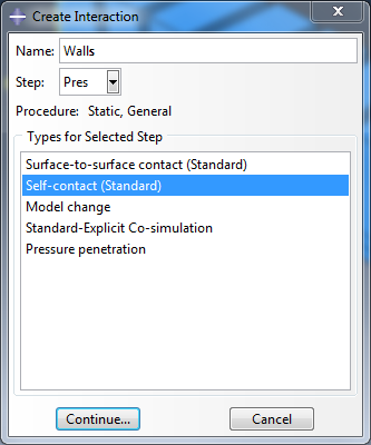
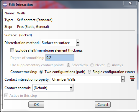
Now we define where/how the above interaction type is going to apply. In the model tree, double-click on Interaction and create a new interaction of type "Self-contact (Standard)." Make sure that this interaction applies during the Pressure step, since that is when the walls begin to touch.
  |
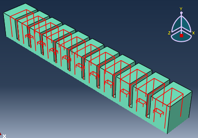
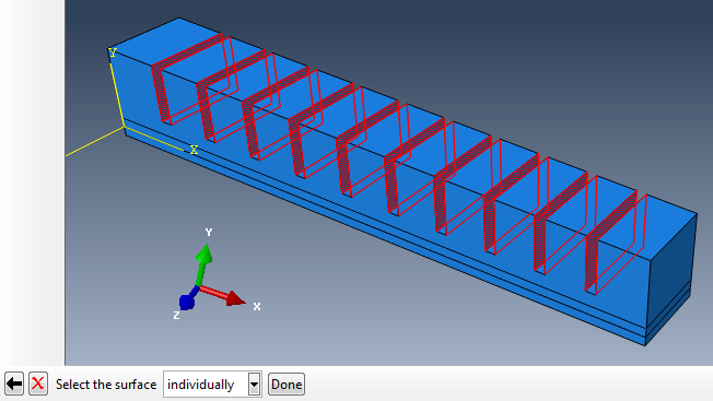
Now, we select the surfaces where the contact will occur. Select all the adjacent chamber walls in the actuator, by clicking on the relevant faces while holding down SHIFT on your keyboard. You will need to rotate your view at least once to select everything. Click the 'Done' button when finished.
One last "Edit Interaction" window will pop up. Use the default settings, seen below:
Mesh
Create mesh
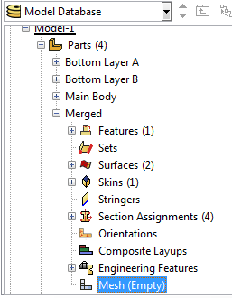 |
Expand the Merged part in the model tree and double-click on Mesh. |
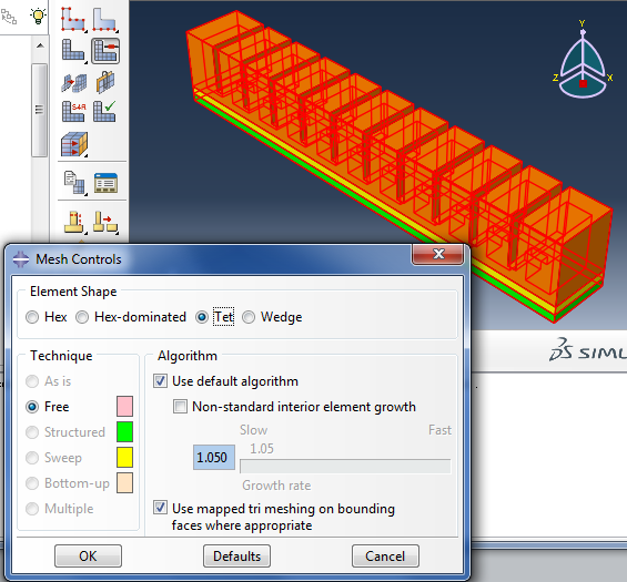
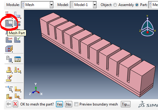
Click the ‘Mesh Controls’ button in the toolbar, then select all the parts of the assembly. In the window that pops up, select 'Tet' for the element shape.
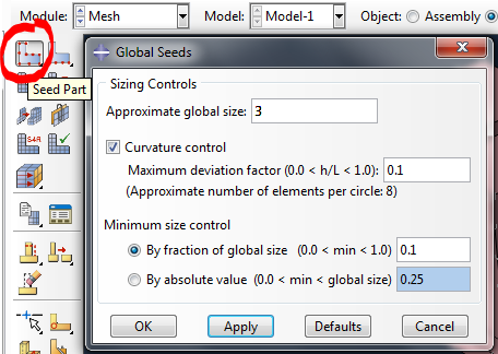 |
Seed the part with an ‘Approximate global size’ of your choosing. If the mesh size is too small, the model may become “stiff” to high distortions. But if it is too big, the mesh will not fit on well on the model face. Here we use a size of 3. |
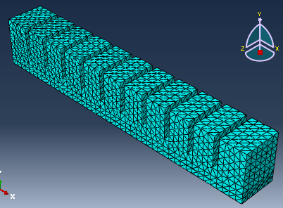
Mesh the part.
Set mesh type
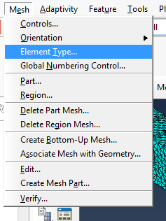 |
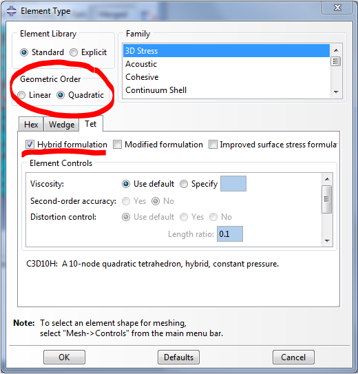
Because we are using a hyperelastic material, a Hybrid element type for the mesh should be used. In the menu bar at the top of the Abaqus window, go to Mesh → Element type, then select the 3 parts for the region (click one by one so you don't include the paper layer). |
Activate the tick on ‘Hybrid Formulation’ for all the hyperelastic parts. Make sure ‘Geometric Order’ is Quadratic.
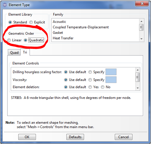
Now do the same for the skin (inextensible layer). First, isolate the surface using the Display Group Manager as before, then again go to Mesh > Element Type. In the new window, change the Geometric Order to Quadratic so that it matches the other elements.
Run job and view results
Run job
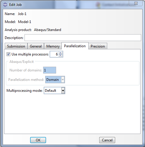 |
[Video: Create, submit and monitor job] Now, we are ready to submit the job and run the simulation. In the model tree, under Analysis, double-click on Jobs to create a new job. You can use the default settings, or change certain options (i.e. multiple processors) so that Abaqus can use more computer resources and complete the job faster. |
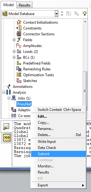
Right click on the newly created job and select Submit.
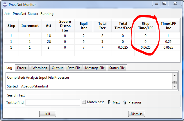
You can monitor the progress of the simulation by right clicking on the job and selecting Monitor. A new window will pop up. In the Step Time/LPF column you can see the percentage completion of that step.
View results
Once the simulation finishes, you can observe and analyze the results by right clicking on the job you just ran, and selecting Results. If you need to keep your results, they are saved in a large .odb file, typically in the TEMP folder or in the same directory as your model (.cae) file.
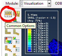 |
There are a several things you can do when viewing results. For example, clicking Common Options lets you tweak the appearance of the model result (i.e. shading, wireframe view, etc.) |
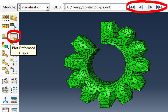
To see what the actuator looks like after gravity and pressure have been applied, click on Plot Deformed Shape. The navigation arrows in the top right corner of the screen allow you to scroll through the step increments and see how the actuator reaches its final shape.
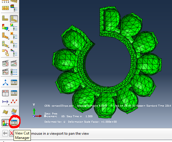
You can use the View Cut Manager to see section views of the deformed actuator, and use the button next to it to easily toggle the view cut on and off.
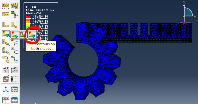
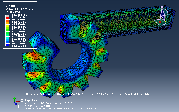
You can Plot Contours on both shapes (click and hold the toolbar button to make this option available), which superimposes the initial and final actuator shapes. This also lets you see the actuator color-coded by stress (Mises). Note that the actuator looks entirely blue (low end of the scale); this is because the highest stresses are in the paper layer, which is not visible, which affects the relative scale that Abaqus uses to color-code the model.
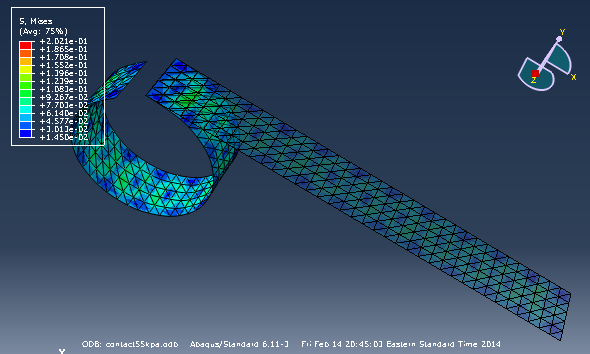
We can verify this by using the Display Group Manager again to isolate the paper layer, and now we can see the color-coded stress.
To see color-coded stress in different areas of the elastomer body of the actuator, we can manually change the scale using Contour Options. Note that by default, the scale limits are auto-computed by the minimum and maximum values in the model results.
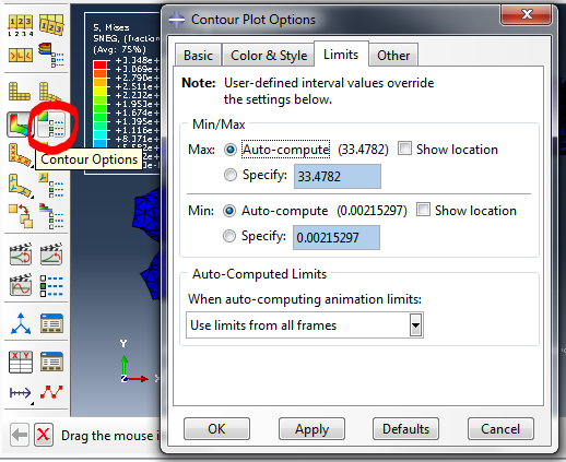
Try specifying the maximum value as 0.5 and note that now you can see the stress color-coding in the actuator.
Testing
This section describes some examples of empirical tests that have been carried out to characterize PneuNets actuators. The aim of presenting these examples is to help you think about what types of tests you may need to perform to help guide your design. You may find the methods described useful for characterizing the behavior of your own actuator designs.
In many of these examples, the researchers conducted the tests in order to validate the results of their Modeling and Analysis. The tests were carried out using an evaluation platform based on the Soft Robotics Toolkit control board.
A summary of the results from these experiments can be found in the Variation: Material and Variations: Morphology sections.
Bending Curvature Estimation
This test was carried out by Polygerinos et al. (2013).
|
One end of the actuator was mounted in a rigid fixture (similar to the "encastre" boundary condition used in the FEM model). The actuator was inflated and the trajectory of its tip was observed. |
 |
|
|
A high definition camera was positioned to view the actuator from the side. The checkerboard pattern in the background was used in registering and aligning the camera (in order to address lens distortion and improve accuracy). As you can see in the photographs (left), a ruler was mounted beside the actuator to provide a scale for pixel-to-length conversion during image analysis. |

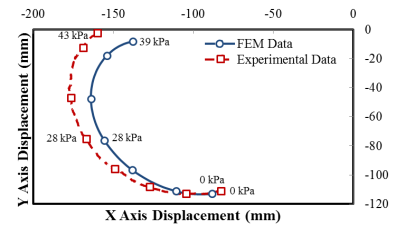
To estimate the trajectory of the tip, the soft actuator was pressurized and depressurized three times while the camera recorded the motion. The resulting image frames were post-processed and analyzed with video analysis software (Kinovea 0.8.15). The x and y coordinates of the actuator tip throughout its motion were tracked, creating a trajectory for the tip’s motion. These coordinates were then used to produce the following graph.
Force Delivery Capability
This test was carried out by Polygerinos et al. (2013).
|
A 6-axis force/torque sensor was used to measure the force capacity of the actuator. Again, one end of the actuator was mounted in a rigid fixture, and a short rod to the force sensor was brought in contact with the tip of the actuator. The pressure inside the actuator was gradually increased in increments of 1 psi, and the force exerted by its tip was recorded. The experiment was repeated three times to assess accuracy and repeatability. |
 |

Effect of Actuator Morphology on Pressure Requirements
Mosadegh et al. (2013) investigated the effect of varying actuator morphology on the pressure required to achieve bending. A variety of actuators, all of the same overall length, were fabricated. The number of chambers, the wall thickness, and the chamber height was varied in each actuator. The actuators were clamped at one end. Each actuator was inflated and the pressure required for it to fully bend was recorded.

Case Study
|
This case study describes the design of a wearable device for hand rehabilitation, and is based on work carried out by Polygerinos et al. (2013). |
 |
Clinical need
Loss of grasping ability, whether caused by injury, disease, or other mechanisms, is a significant problem which negatively impacts quality of life in patients. It is possible to recover some lost function through intensive physical therapy, which typically involves the use of repetitive task practice (RTP).
However, RTP requires a therapist to assist the patient and guide the hand through the correct motions. As RTP also needs to be performed continuously for several hours, this results in high therapy costs and limits the number of patients a therapist can see. The aim of this project was to develop a wearable device to enable patients to perform RTP on their own, whether at home or in a clinic, in order to improve the accessibility and effectiveness of therapy.
Solution
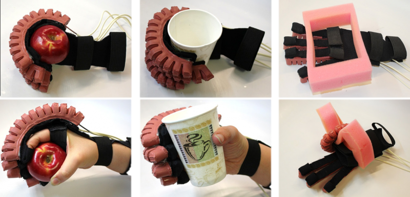
The proposed solution was a glove incorporating four PneuNets bending actuators sitting atop the fingers. When pressurized, the actuators bend and cause the fingers to flex, assisting in a grasping/close-fist motion.
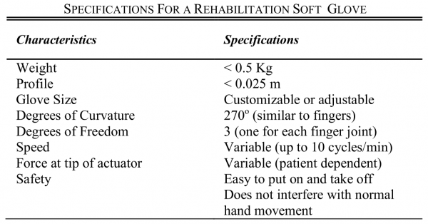
A list of required specifications for the glove was determined through a review of the medical literature and discussions with clinicians.
FEM analysis was used to predict the effect of changing various actuator design parameters and guide the design. This design was then fabricated and tested on an evaluation platform to validate the FEM results and verify that the required specifications were met.
To interface with the patient, the actuators were attached with thin Velcro straps to an open-palm glove, made of an elastic material (neoprene) that would conform well to the hand at all bending angles. Small pockets were added at the fingertips to secure the actuators to the fingers. The glove prototype was tested for its ability to grasp objects of a wide range of sizes, shapes, and stiffnesses.
Downloads
Files for fabrication
- CAD (SolidWorks) files of PneuNet molds (.zip)
- STL files of PneuNet molds for 3-D printing (.zip)
- Detailed Bill of Materials (.xlsx)
Files for modeling
- Simplified CAD files of PneuNets for FEA (.zip)
- STEP files of PneuNets to import into Abaqus (.zip)
- CAE input file for Abaqus PneuNet model (.zip)
| Some of the information contained in this web site includes intellectual property covered by both issued and pending patent applications. It is intended solely for research, educational and scholarly purposes by not-for-profit research organizations. If you have interest in specific technologies for commercial applications, please contact us here. |