Mold Design CAD Tutorial
This tutorial contains step-by-step instructions for making a solid model of a PneuNets bending actuator mold in SolidWorks. The SolidWorks part files can be downloaded here. If you prefer to use a different software package, you should be able to apply the general tutorial steps to most solid modeling environments or you can refer to the dimensioned drawing below to guide you.
|
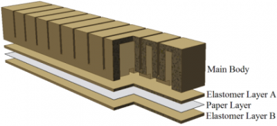
As discussed in the previous pages, this actuator consists of two parts: the main body, which expands when inflated, and an inextensible base layer composed of a piece of paper embedded in elastomer. The two parts will be cast separately and then glued together, so we will need separate molds for the main body and the base layer. |
|
|
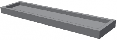
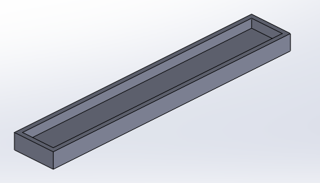
The mold for the base layer is simply a flat rectangular plate with a lip around the edges. |
|
|
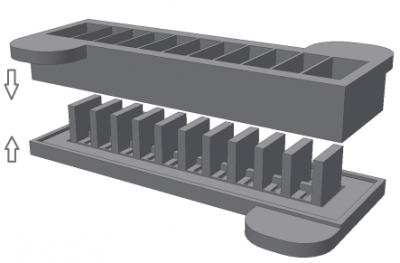
The main body is more complex, and is cast in a two-part mold. The mold contains overhangs, and if we were to use a one-part mold, we would have to destroy it in order to remove the actuator once it was cast. By using a two-part mold we can reuse the same mold again and again.
|
|
|
Before making our mold we must decide its morphology (See this page for a discussion of PneuNets morphology). There are several dimensions that affect the actuator’s behavior: chamber height, sidewall thickness, spacing, and overall number of chambers.
|
|
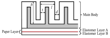
In addition, there are other dimensions to be determined: chamber width, thickness of the other chamber walls (which must be thicker than the sidewalls so that they don’t expand much in comparison), and size of the central channel.
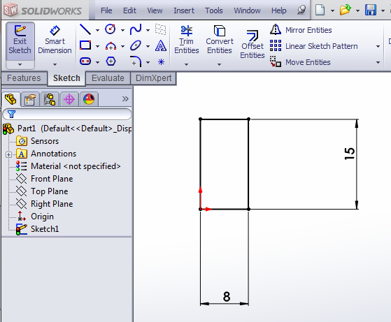
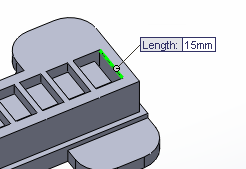
In this tutorial we will make an actuator with 11 chambers. Each chamber is 8mm long, 15mm wide, 15mm high, has 1mm sidewall thickness, with other walls being 2mm thick, and is spaced 2mm from the next chamber. The central channel will have a 2mmx2mm cross-section. Of course, you can alter these numbers to change the morphology of your actuator and the general steps covered in the tutorial should still apply.
We will first create a solid model of the actuator, and then use this to derive the solid models for the mold pieces by following these steps:
- Encasing the actuator in a solid block
- Subtracting the actuator from the block
- Separating the resulting shape into top and bottom mold pieces

| PneuNet Molds SolidWorks Files (.zip) | 729 KB |
Design Individual Chamber
There are 2 main ways to make the actuator body: we can design a chamber and then multiply it in a linear pattern, or we can make a long rectangular solid and make several linear patterns of cuts. Here we will use the first method as it involves less arithmetic. [Video: Making a chamber unit]
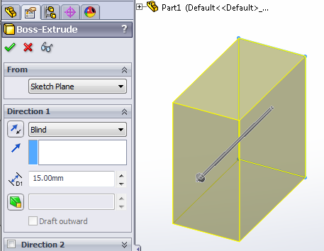
Using the Extruded Boss/Base feature, create a 8x15x15 (mm) solid block.
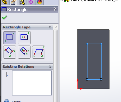
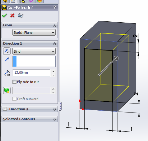
Now we need to cut out the inner cavity of the chamber. Select the Extruded Cut feature, and make a sketch of a rectangle on the bottom face of the block. Using the Smart Dimension tool, set the offset from the block edges to the appropriate wall thicknesses.
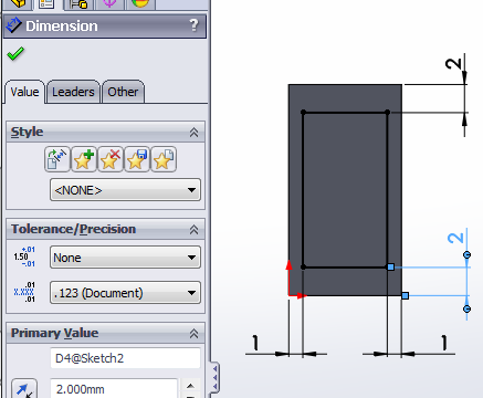
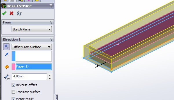
Since we want the top wall thickness to be 2mm and the block is 15mm tall, we will make the extruded cut 13mm deep. (Alternatively, instead of a Blind cut, use Offset From Surface and set it to be 2mm from the top of the block.)
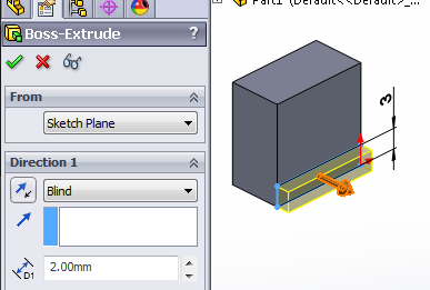
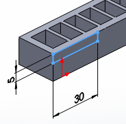
Now we need to make a strut between each chamber and the next. It will be 2mm thick, since that is our desired distance between chambers. To determine the height, we need to make sure that it is tall enough to allow room to cut out the central channel. Since the channel is 2mm tall, we will make the spacer 3mm tall.
Once again, use the Extruded Boss/Base tool and extrude a spacer block from the side of the chamber.
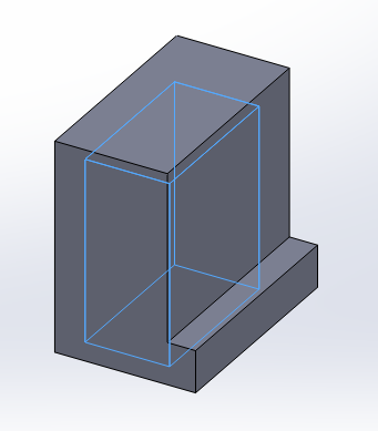
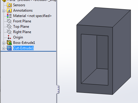
Now the chamber is complete. In the next step, we will create multiple copies of this chamber and combine them to create our actuator
Combine Chambers
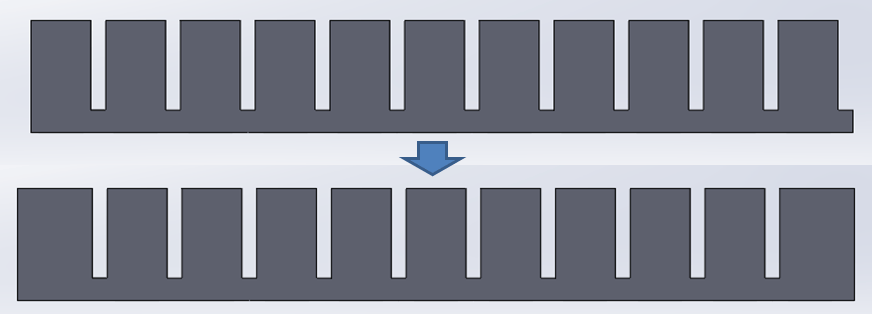
Now that we have the basic chamber, we will repeat it to create row of 11 chambers using the Linear Pattern feature. Since we need to pattern the entire chamber, we use Bodies to Pattern (instead of Features) and click on the chamber that we made. [Video: Patterning chambers in a row]
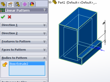
Now we select the direction to pattern the chamber. Under Direction 1, select an edge to determine the direction of patterning. You can use any edge parallel to the actuator main axis.
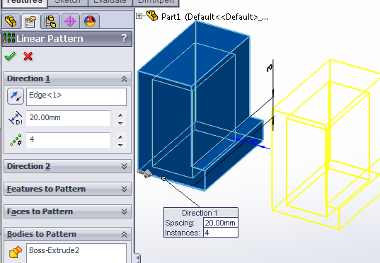
Set the distance to 10mm (8mm chamber thickness + 2mm spacer) and the pattern # to 11.
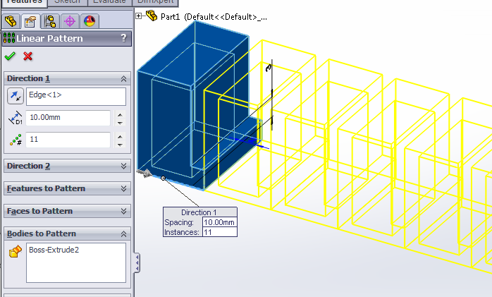
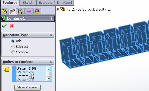
This gives us 11 separate solid bodies, which could be annoying later, so we merge them into a single solid body using the Combine feature.
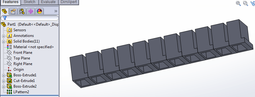
In Combine, use the Add operation type to add all the chamber bodies together. Under Bodies to Combine, select all the chambers.
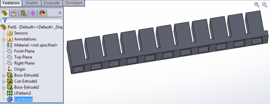
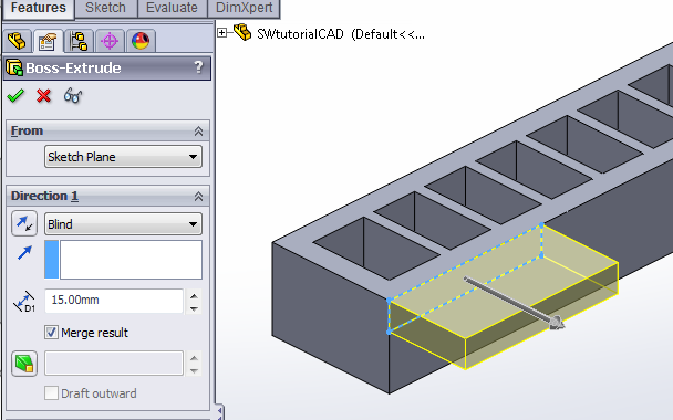
Next, we need to thicken the two ends of the actuator so that they don’t bulge out like the other sidewalls. To do this, use Extruded Boss/Base twice, to add 2mm extra thickness to each end wall. [Video: Thicken actuator ends]
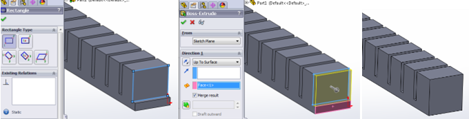
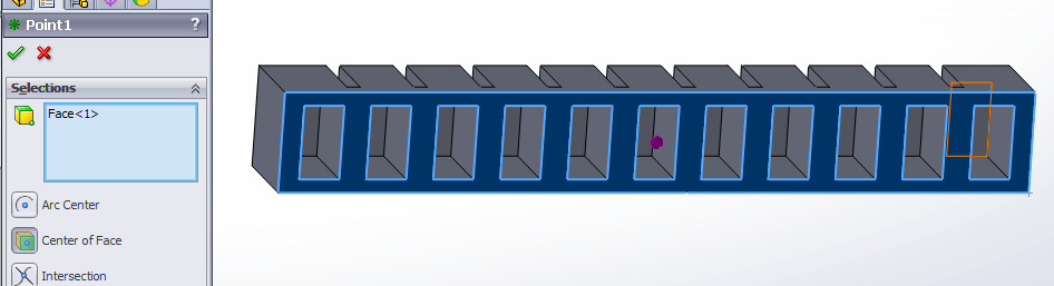
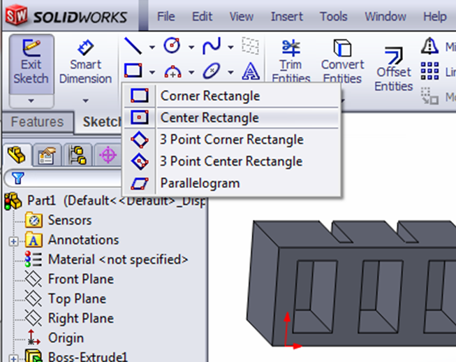
Now we cut the 2x2 mm central air channel. [Video: Cutting central air channel] To ensure that it is centered along the axis, we first need to create some reference geometry: a point that we can use to draw a centered rectangle later.
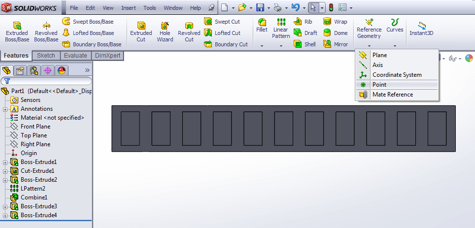
In the Point sidebar, select the “Center of Face” option, then click on the bottom face of the actuator (not inside a chamber). A dot should appear at the center.
Now we use Extruded Cut to create the central channel. On the bottom face of the actuator, draw a rectangle using the reference point we just created as its center, and having its edge coincide with the inner face of one of the end chambers.
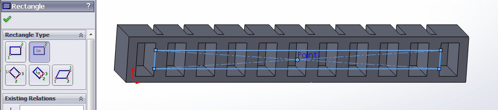
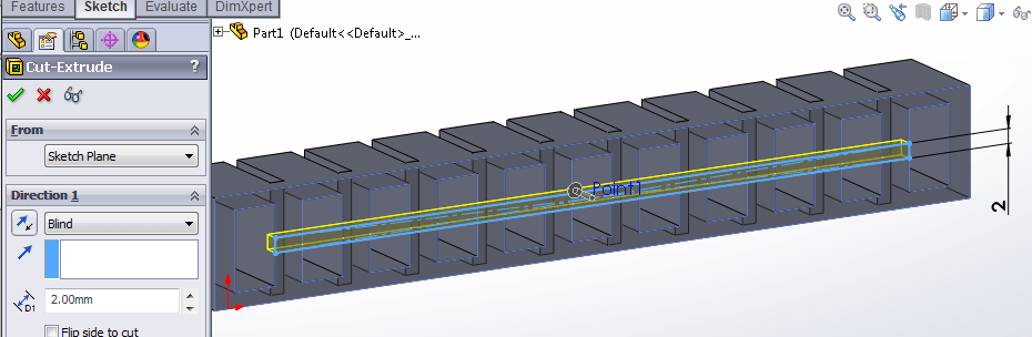
Use Smart Dimension to make the rectangle 2mm wide, then exit the sketch and make the Extruded Cut 2mm deep.
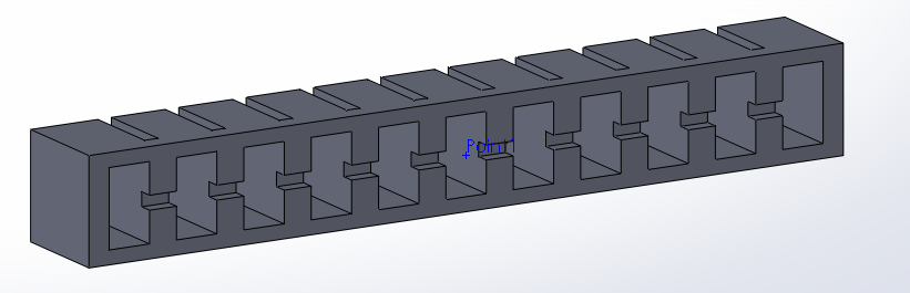
The main body of the actuator is now complete, but in the next step we will add some extra features to aid fabrication.
Add Bonding Features
We now have the main body of our actuator. We can add some extra features to aid fabrication: when we are gluing the main body to the base layer, ridges and bumps will improve bonding between the parts by providing more surface area for the glue to adhere to. Adding some extra height to the main body also helps to prevent the glue from blocking the central air channel.
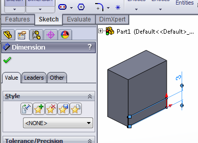
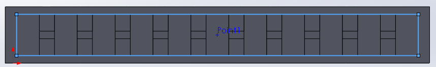
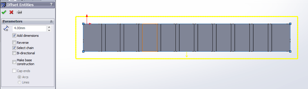
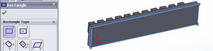
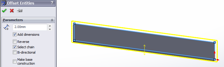
First we add a ridge around the perimeter of the bottom, using Extruded Boss/Base. On the bottom face of the actuator, draw a rectangle that encompasses all the of chambers.
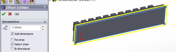
Next, while this rectangle is still highlighted, use the Offset Entities tool to create another rectangle that is offset 1mm outwards. You may have to check the “Reverse” option for the offset to go the right way.
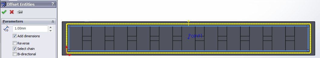
Exit the sketch and extrude the ridge 2mm.
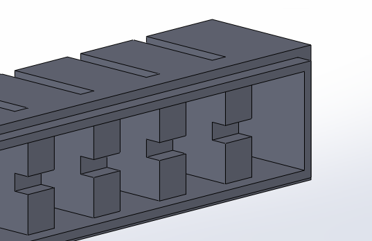
Next, we add bumps on each strut. [Video: Make bonding bumps] First we make bumps on one strut using Extrude, then we use Linear Pattern so that every strut has bumps.
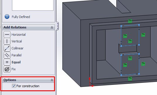
On the bottom face of the actuator, select the bottom of the strut (2 separate faces because the air channel cutting through the middle), then click on Convert Entities.
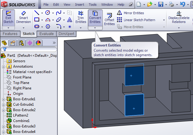
This will turn the edges of those faces into rectangles in your current sketch. Select both rectangles and mark them for construction.
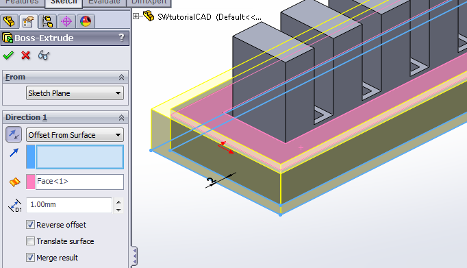
While the rectangles are highlighted, select Offset Entities again, making new rectangles that are offset 1mm inwards from the construction rectangles (you may have to select “Reverse”).
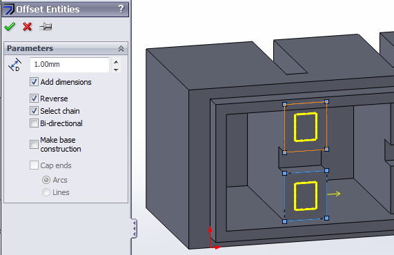
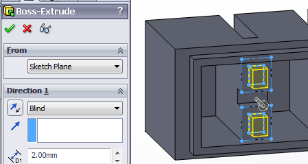
Click the checkmark to create the offset rectangles, exit the sketch, then extrude the rectangles 2mm.
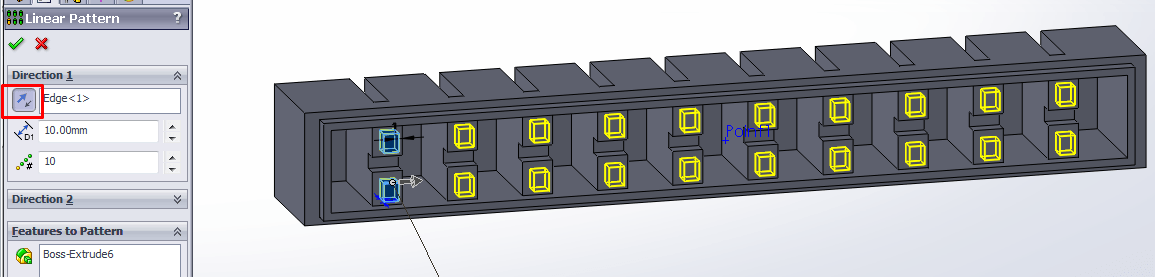
In the sidebar, select the extruded feature you just made, then click on the Linear Pattern tool.
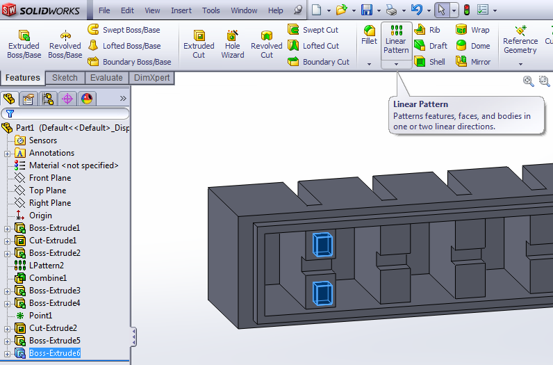
Once again, select an edge parallel to the actuator’s long axis (you may have to reverse the direction – the button highlighted in red below), and use 10mm for the pattern spacing. However, reduce the pattern number to 10, since there is 1 less strut than the total number of chambers.
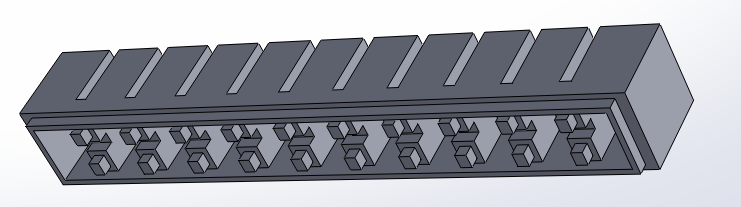
Now the main body of our actuator is finished. In the next step, we will use this main body model to create our molds
Make Main Body Molds
Now that we have made a model of the main body we can use it to model the mold required to fabricate it.
With Extrude, encase the actuator in a rectangular block, leaving about 4mm padding on every side, except for the top which should be flush with the top of the actuator. [Video: Encase actuator in mold block]
The simplest way to do this is to draw on the top side of the actuator. Make a construction rectangle that encompasses the entire face, then make a 4mm outwards offset using Offset Entities.
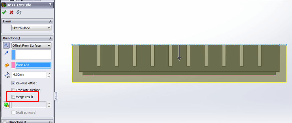
Extrude this large rectangle so that it encases the actuator, going 4mm past the bottom-most face of the actuator (the bonding ridge). You may have to reverse the direction and/or the offset. Make sure to uncheck the “Merge Result” option.
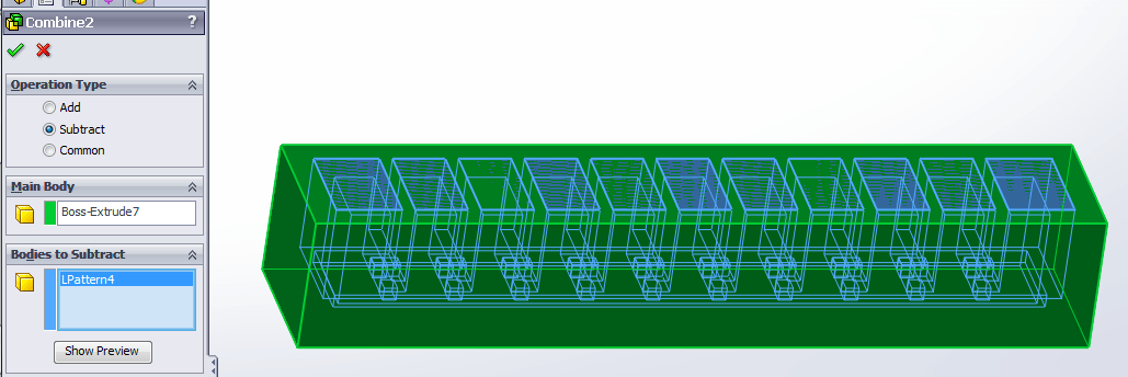
Next, we need to subtract the actuator body from the encasing block to get our mold. [Video: Subtract actuator from block] We do this by using the Combine feature again, but this time using the “Subtract” operation. Choose the encasing block as the “Main Body” and the actuator CAD model as the “Bodies to Subtract.”
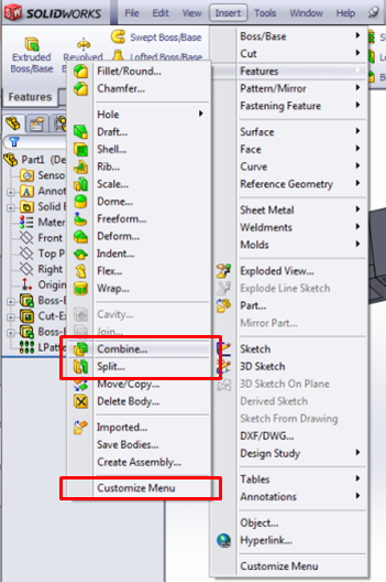
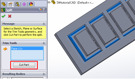
We now have a mold; however, as it is, we cannot remove the molded piece without breaking the mold. We now have to divide the mold into 2 separate pieces which can be pulled apart for demolding. To do this, use the Split feature (Insert > Features > Split). [Video: Split mold]
When using Split, the user must choose the plane along which the split occurs. Click the box under Trim Tools so that it is highlighted, then select the face for splitting.
The face we want is the one that corresponds to the bottom of the actuator, excluding the bonding ridge/bumps. Look at the mold from the top, where the holes are, and select the rectangular face closest to the outer wall of the mold. (The inner one is the depression corresponding to the bonding ridge on the bottom of the actuator.)
Once the face is selected, click the “Cut Part” button.
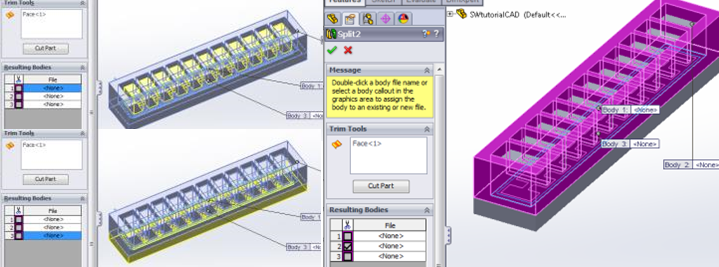
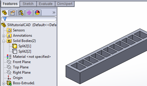
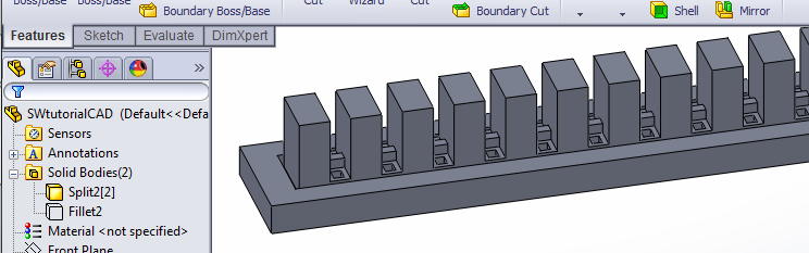
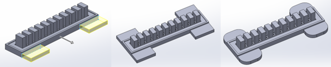
The cut will result in 3 bodies. Select the one that looks like a ladder (as in the last image) and check its box, then finalize the Split by clicking the green check mark.
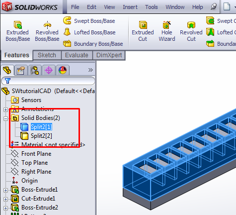
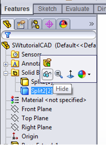
There should now be two solid bodies in this document, one corresponding to the top mold piece and one for the bottom. You should be able to see them near the top of the FeatureManager Design Tree on the side of the window.
We will edit each of these bodies to add features that make the molding process easier. First, hide the bottom body so that it doesn’t clutter the view while we edit the top part. Click on the bottom body and a small menu will appear. Click on the glasses icon to hide the body.
Now, only the top mold piece should be visible:
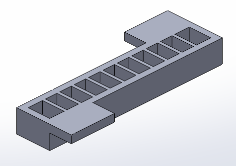
To this piece, we will add tabs on the side to provide grip when pulling the mold pieces apart. [Video: Edit top mold piece] Use Extrude and draw a rectangle in the top corner of one of the side faces. Extrude it out to create a tab. Repeat for the other side.
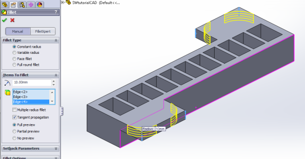
You can round out the grip tab corners so it looks nicer (though it is not necessary) by using the Fillet tool, and selecting the 4 sharp edges of the tabs.
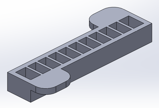
This piece is now complete and ready for printing. Save it as an .STL file (or whatever file format your 3D printer uses): File > Save As and set “Save as type” to STL (*.stl)
Now we need to edit the other half of the mold. Hide the current body, and unhide/show the other one (using the glasses icons again). [Video: Edit bottom mold piece]
To this part we will add a raised lip around the perimeter to help align the two mold pieces.
An easy way to do this is to Extrude an offset from the flat bottom face of the part. Draw a rectangle that encompasses the entire bottom face, then while it’s still highlighted, use Offset Entities to create a small outwards offset.
Once this sketch is complete, extrude it upwards, towards the top of the mold piece, so that it’s raised slightly above the mold floor, creating a lip. You may have to reverse the direction, or if you use “Offset from Surface” you may have to reverse the offset.

Now that the alignment lip is complete, create tabs for this piece as well, using the same method as before. Once the piece is complete, save it as another .STL file.
The molds for the main body are now complete. In the next step, we will make the mold for the base layer
Make Base Mold
Now we have to make the mold for the actuator’s base layer. This is simply a rectangle that has the same dimensions as the main actuator, with a 4mm raised lip around the edge.
Measuring our actuator (Evaluate > Measure) gives us the dimensions 112mm x 15mm.
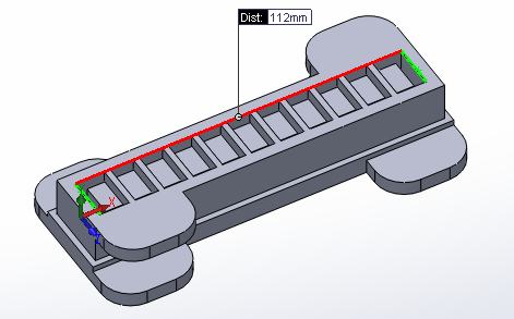
Extrude a 112mm x 15mm rectangle to 3mm thickness. Use the same method as before, with the alignment lip, to create a 4mm high lip around this mold.
The completed base mold should look like this:
Save it as a .stl file.
The mold solid models are now complete. You can use the .stl files you have created to make the molds with a 3D printer.