SDM Fingers
Shape Deposition Manufacturing (SDM) is a rapid prototyping process in which mechanisms are simultaneously fabricated and assembled through alternating steps of subtractive (milling) and additive (casting) manufacturing. One of the advantages of this process is that it is possible to embed items (such as sensors, motors, or structural reinforcements) into the mechanism you are building. Further information on SDM can be found here: [External link].
In this documentation set we will use SDM to build multi-jointed, compliant fingers that are actuated by pulling a cable. This technique is based on work carried out at Harvard (Dollar & Howe, 2006) and Stanford (Binnard & Cutosky, 2000) to build graspers for dexterous robot manipulation.
 The compliant nature of the fingers allow for grasping of a wide variety of objects, and the embedding of components makes them resistant to damage. In the below video, the i-HY hand, which uses SDM fingers, picks up objects ranging from a basketball to a door key. It is also hit several times with a baseball bat but still functions normally afterwards:
| Some of the information contained in this web site includes intellectual property covered by both issued and pending patent applications. It is intended solely for research, educational and scholarly purposes by not-for-profit research organizations. If you have interest in specific technologies for commercial applications, please contact us here. |
Design
 |
The diagram on the left shows the basic structure of the finger. When tension is applied to the cable (orange), the compliant material (blue) deforms and causes the finger to bend. We will make the finger using a two-step molding process. Referring to the diagram on the left, in the first step we will cast the (red) structural, high-modulus material while embedding a channel for the cable. We will then use a CNC mill to cut the mold for the second step, and use this mold to cast the (blue) flexible, low-modulus material. Finally, we will add the cable. |
Variation: Morphology
|
By varying the lengths and thicknesses of the finger links, the stiffness and corresponding bending behavior of the fingers can be altered. In the image to the right, the number and lengths of the compliant and rigid finger sections were varied. An equal load was applied to each cable and the resulting effects on bending can be seen. |
|

Other Variations
As with all bending actuators, material selection defines the bending behavior as a lower durometer material will exhibit larger deformations, and vice versa.
One of the advantages of the SDM process is that it is possible to embed objects in the finger during fabrication. Embedding different items, such as pressure sensors at the finger tips, or structural reinforcements within the compliant sections, can change the functionality of the fingers.
Fabrication
The general fabrication process for SDM parts is as follows:
- Make a mold defining geometry of a subsection of your
- Position components in the mold
- Pour/inject material into mold and cure
- Repeat steps 1-3 as necessary. the subsections that have previously been cast now become components embedded in a new larger mold.
- Remove part from mold
The specifics of the process depend on the complexity of the desired final SDM part. There are 2 general methods: open-top molding and closed-top molding.
Open-top molding works for simpler geometries. Molds are made by milling pockets into wax blocks, so the part shape is limited by the fact that the inverse shape for the mold is millable. For example, the left-most shape in the below image is simple to make, the center one would require 3D CNC milling but is still possible, while the last shape cannot be made.
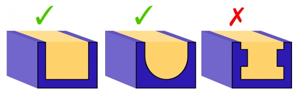
In addition, since the casting material is liquid and poured into the mold, the top of the part will be flat, as that is how the liquid material settles.
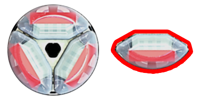
Closed-top molding allows for more complex part geometries. For example, the fingers used in this case study needed to be compact and fit within a cylindrical delivery tube. This meant that the fingers had a cross-section with undercuts on both sides, highlighted in red below, which was not achievable with open-top molding. However, a 2-part closed-top mold was able to make this geometry.
Mold design for closed-top molding is more complicated -- molds have to be 2-part so that the final result can be removed, and additional features such as injection ports and sprue holes have to be included. The molds also need to be 3-D printed as they are impossible to machine.
Open-top molding
The open-top molding process is used to create monolithic multi-segment fingers with simple morphologies. The following is an illustrated step-by-step tutorial on using SDM to manufacture a simple 3-jointed finger using an open-top wax mold. In the diagrams below:
- RED indicates a milling/machining step,
- GREEN indicates a component placement step, and
- BLUE indicates a filling step.
Personal protective equipment (lab coat, safety glasses and latex or nitrile gloves) should be worn at all times. Filling and mixing should be performed inside a fume hood.
Download a .zip file containing the Solidworks part file as well as g-code for the 2 machining steps HERE
MINIMUM Materials
- Wax blank (for example, MSC.com)
- High-modulus plastic for stiff segment. Here we will use Task-9, a 2-part urethane plastic from Smooth-On.
- Low-modulus elastomer for soft segment. Here we will use PMC-780, a 2-part urethane rubber from Smooth-On.
- Tubing for cable routing. For example: High-Pressure PEEK Tubing, .020" ID, 1/16" OD, .021" Wall Thickness, Orange (McMaster P/N: 51085K45)
- Cable for actuating finger (several material options here, such as steel wire, Nitinol wire, or Kevlar thread)
- Any fastening materials (application-dependent). Here we will use a 10-32, 3/4" screw and a 10-32 hex nut.
- Modeling clay/crafter's clay
STEP 1: Milling
Starting with a wax blank, mill pockets for the stiff segments, as well as any pockets/channels to hold components that will be embedded within the stiff elastomer. Invariably this will include a cable sheath (plastic tubing), and it could also include any embedded fasteners (screws, nuts) or sensors. You should select an endmill with a diameter equal to the smallest feature you need to cut. In this case the smallest feature is the pocket for the cable-routing tubing which is 1/16" wide, so we will use a 1/16" endmill.
Recommended cutting speeds for machinable wax are (from http://www.machinablewax.com/technical.php):
- Roughing: Spindle speed 3,000 rpm at ~ 100 inches per minute
- Finishing: Spindle speed 8,000 to 10,000 rpm at ~ 40-100 inches per minute
- Depth of cut: roughly 1/2 Tool Diameter

STEP 2: Placement
Place components that you wish to embed in the finger inside the mold. In the figure below, these components include 1 cable sheath, one flathead screw and 1 nut to locate the screw within the proximal-most segment. These components will be embedded within the stiff elastomer. Place crafter’s clay into any small areas where you don’t want the elastomer to fill (for example, on the portion of the screw threads that will be outside the finger, over the cable tubing in between each finger segment).

STEP 3: Filling
Thoroughly mix Task-9 parts A and B (in a 1A:1B ratio by volume). Be wary of the 'pot life' (i.e. working life) of the plastic; for Task-9 this is about 7 minutes. Slowly pour the mixture into the pockets until the mixture is flush with the surface of the mold. Place mold inside a vacuum chamber to degas the elastomer and wipe away any bubbles from the surface. Try to ensure that no elastomer ‘bleeds’ over on the top surface of the wax mold. Once sufficiently de-gassed, place entire mold in a safe place and let it cure for a couple of hours at room temperature.

STEP 4: Milling
Machine pockets for the flexible segments. The profile shown below is a ‘dogbone’ profile to ensure positive engagement between the flexible and stiff segments (although other profiles are possible). This time, we want to use speeds and feeds appropriate for the stiffest material which is the Task-9 polymer, not the machinable wax. Recommended speeds/feeds for Shore D 85 polyurethane:
- Roughing: Spindle speed 1600 RPM at 40-60 inches per minute
- Finishing: Spindle speed 5000-10000 RPM at 100 inches per minute
- Depth of cut: roughly 1/2 Tool Diameter

STEP 5: Filling
Mix PMC-780 parts A and B (in a 2A:1B ratio by weight or by volume). Fill pockets with the mixture and follow the same procedures described in Step 3 to ensure adequate degassing and curing. Set aside for the recommended curing time.

STEP 6: Release
Once fully cured, the assembly is ready to be released. The wax blank used in this lab is 1.5" thick, with the finger only occupying 0.5" of the thickness. Use a bandsaw to take down the wax blank thickness to 0.75" or so and cut out some wedges in the wax around the finger to act as stress concentrators. Use a vice to (carefully) compress the wax mold and break it off around the finger, ensuring that you minimize the amount of torsion being placed on the flexible joints as they can tear. Once the finger is released, trim the excess non-embedded portions of the cable sheath (from the ends and from in between the stiff segments). Feed the cable through each joint and tie off at the end. The finger is complete!

| SolidWorks part file + mold milling g-code | 284 KB |
Closed-top molding
For fingers with more complex cross-sections that cannot be achieved with open-top molding, we can 3-D print two-part, closed-top molds. A complication of the closed-mold approach is the inability to machine the pocket for the flexible joint material. As such, a separate molding process must be performed to mold the flexible joints independently. This section does not provide a definitive guide to mold design; however it does present a case study and describes factors of the closed molding process that must be taken into consideration.
Considerations for closed-top molding
The fabrication process for closed-top molds is slightly different from that for open-top molds:
1. Mold Release: Apply liberally. This is very important. Unlike wax, 3D-printed resin cannot be broken and easily separated from the molded finger. Also spray on the clamping surface so any elastomer leakage doesn’t lock the mold shut once cured.
2. Component Placement: Your molds should contain features to align any components you want to embed in the finger.
3. Closing the Mold: Clamp tightly with socket-head cap screws.
4. Degassing: In contrast to the open-top mold, it is best to degas the elastomer before injecting into the mold. Limited exposure to the air makes it difficult for bubbles to escape once the fluid is injected into the mold, creating voids in the finished part.
5. Filling: As the mold is closed, you will likely need to use a syringe to inject fluid into the segment cavity. This must be done very carefully and slowly so you don’t introduce bubbles into the mold. If possible, use a translucent material as your mold material so you can visually inspect the quality of the injection. Depending on the viscosity of the fluid, gravity might not be enough to adequately fill tight spaces within the cavity. A good technique is to design inflow and outflow sprues into the mold, wherein the fluid is injected into the segment cavity at one location, and allowed to eject from the cavity at another location. This allows the fluid to circulate and leverages the pressure differential to fill the cavity.
Closed-top mold design
The following image shows the features of a closed mold used to fabricate a 3-jointed SDM finger with an embedded pressure sensor.
|
|
|

Closed-top molding steps
Step 1: Mold the individual flexural components first. This can be done using an open-top molding process.
  |
 |
Step 2: Place the various flexural components, as well as the cable sheath and any sensors/wiring, into the master mold. |
 |
Step 3: Close the master mold and tighten securely with screws. |
 |
Step 4: Carefully introduce high-modulus elastomer into each compartment using a syringe. |

Modeling
When designing multi-segment compliant fingers with shape deposition manufacturing, deterministic tools should be sought to ensure that relevant design criteria are met (for example, finger stroke or transmission ratio). Finite element simulations can be employed for this task. However, the behavior can also adequately be described using first principles and beam theory.
Please read this document for a detailed description and derivation of the analytical model.
An illustration of an tendon-driven finger with a single compliant joint is shown in Figure 1. The finger consists of a rigid section (subscript s) and a flexible section (subscript f). Material properties alternate from low-modulus (Ef) joints and high-modulus (Es) segments. The finger is actuated by a tension force T which establishes a moment about the distal-most compliant joint.

The simplified model assumes that the deformation behavior is dominated by an applied moment M=Th at the distal segment of the finger and contributions from gravity and reaction forces in the x-direction are negligible. We can use superposition to determine the overall deflection at the distal end of the finger by propagating internal moments back to the proximal end and defining a global displacement with respect to the origin of the proximal-most segment (the global origin).
The exact behavior of the low-mod flexible joint is difficult to model analytically. Typically, rubber elastomers are modeled by the Mooney-Rivlin hyperelastic model, which contains coefficients that must be empirically determined. An example curve comparing a Mooney-Rivlin fit to a linear elastic approximation for urethane is shown below; observe a ~15% error between models at 10% strain.

A linear approximation to the stress/strain behavior is suitable for qualitatively evaluating different configurations for relative performance. An example of such an analysis is shown below, where three different finger configurations were compared both analytically and empirically. In the left-most finger, the joint stiffnesses are proportionally decreasing from proximal to distal, resulting in a large deflection of the distal-most joint. The middle image shows a finger where each joint stiffness is identical, and it behaves more like a cantilever beam. Finally, the right-most image shows a configuration where the middle joint is the weakest.

A rigorous derivation of an approximate model, as well as MATLAB source code, is in the attached .pdf. The attached zip file contains the MATLAB files.
| Derivation of Bending Analytical Model (.pdf) | 744 KB | |
| MATLAB code for analysis (.zip) | 20 KB |
Testing
|
To ensure that the finger design is suitable for the given application, we need to know the relationship between how hard the cable is pulled and the resulting forces at the finger tip. While modeling can give an estimate, it is important to validate these models empirically as well. The transmission ratio can be determined by measuring the tension force in the pull cable using a force gauge, and measuring the resulting force at the distal segment of the finger as it pushes against a 3-axis load cell. |
|

 |
In the work by Gafford et al. (2014), the results of the empirical testing were compared to the results of the analytical model, and are shown in the graph on the right. The measured transmission ratio is about 23%, which is very close to the theoretical value of 25% as predicted by the analytical model. |
Case study
This case study describes work by Gafford et al. (2014). The team developed a deployable atraumatic grasper with on-board pressure sensing, allowing a surgeon to grasp and manipulate soft tissue during minimally-invasive pancreatic surgery.
Clinical need
Due to the size limitations imposed by minimally-invasive surgery, current laparoscopic tools used to retract or manipulate delicate tissues are morphologically simple in nature, with fulcrum-based, rigid, steel components incapable of sufficiently distributing forces. This often leads to tissue damage and inadvertent perforation of thin-walled, high-pressure vessels including the superior mesenteric artery and vein (SMA, SMV), and the portal vein, as shown in the figure below. Any amount of intraoperative bleeding can block the surgeon’s view of the workspace, greatly complicating an already taxing procedure. If the hemorrhage is not controlled in a timely manner, the surgeon may be forced to convert the procedure to an open surgery to prevent the patient bleeding to death.

Solution
The team's solution consists of SDM fingers (fabricated using closed-top molding to allow the grasper to fit through a 15mm laparoscopic port) attached to a latching mechanism which holds the fingers in the "grasping" position. The fingers can be released by turning the handle of the device, allowing quick release. The fingers contain Takktile pressure sensors which alert the surgeon when too much pressure is being exerted. An overview of the device is shown in the image below.

The use of soft, compliant materials in making the fingers helps to ensure that the grasper will not cause trauma to the pancreas or surrounding vessels. The use of SDM allowed the team to embed pressure sensors, steel structural elements, and cables inside the fingers to improve functionality.
To converge on a finger design appropriate for a pancreatic grasping application, the team prototyped several variations on the morphology of the finger, as described here. After testing different lengths and stiffnesses of finger segments and connecting links, a 3-joint finger with proportionally decreasing joint stiffnesses was chosen. Force and transmission ratio were estimated using an analytical model, the results of which were validated via bench testing.
Downloads
Files for fabrication
Files for modeling
| Some of the information contained in this web site includes intellectual property covered by both issued and pending patent applications. It is intended solely for research, educational and scholarly purposes by not-for-profit research organizations. If you have interest in specific technologies for commercial applications, please contact us here. |