Using the Control Board
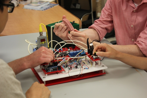
Once you have built the board, you can start using it to control your soft fluidic actuators. This section contains some guidelines on using the board. For basic testing of your actuators (e.g. the type of motion they undergo when inflated, checking for leaks) it is probably sufficient to operate the board manually by using the switches and the potentiometer to vary the pressure and open and close the valves. You can also use the Arduino IDE to write some code that will automate the operation of the control board, for example if you want to test the fatigue strength of your actuator or you want to test out some predefined motion sequences. The Basic Control page discusses how to use the board in these ways.
For more advanced control, you can also use the Arduino IDE to write control software. Alternatively, you can use environments such as LabVIEW or Simulink to create the control or data acquisition software to run on the microcontroller. The Advanced Control page discusses some of these options.
Basic Control
Note: Always check the maximum air supply you provide to the system. Every component has its own specifications and can withstand different maximum pressures.
Basic manual control
- Power the board by plugging in the power adapters. Be careful not to mix up the cords, as incorrect supply voltages will cause some components to burn out.
- Flip the switch to turn on the air pump.
- Try closing the manual flow valve. You should see the pressure reading on the regulator increase from 0 psi.
- Turn the potentiometer dial to control the regulator pressure. The reading on the regulator should change accordingly.
- Re-open the manual flow valve, and flip the switch(es) to open the solenoid valves, making sure that the corresponding relays are on as well. The behavior may be a little counter-intuitive since these solenoid valves are the "normally closed" model, which only open when they are powered. If you have the valves correctly open, you should be able to feel air coming out of the control board's output hose.
- Connect an actuator and turn the potentiometer dial to control how much pressure it receives. Try making it go through its entire range of motion.
Basic Arduino control
If you haven't done so already, set up your Arduino Uno microcontroller using the official setup guide: Windows / Mac
If you were able to get the guide's Blink example to work, you're ready to write and upload your own custom code to control the board hardware. Those already familiar with Arduino programming can use and customize this sample code for monitoring the sensors and controlling the valves. Otherwise, read the brief tutorial below about basic Arduino coding.

First, we define some variables to assign and help keep track of what the various pins are connected to. By using these variables, we don't have to update numbers throughout the code every time we change the wiring. The flow sensor and potentiometer output analog voltages, so we connect them to the analog input pins A0 and A3, as seen in the wiring diagram in the assembly instructions.
The valve (via the relays) and the pressure regulator are controlled by output signals from the Arduino. The analog pins are input only, so we need to use the digital pins. There are 14 numbered digital pins on the Arduino Uno. Pins 0 and 1 cannot be used because we are also using serial communications, so we use Pin 2 for the valve.
For the regulator, we need a continuous control signal, unlike the valve which only requires a binary on/off signal. The Arduino has 6 pins capable of pulse-width modulation (PWM), which are marked by a ~ next to the pin number. We use one of these pins, Pin 9, to control the regulator.
We also create the variables flowReading and potValue to store the values that the Arduino reads from the flow sensor and potentiometer.
| 1 2 3 4 5 6 7 |
int flowPin = A0; int potPin = A1; int regPin = 9; int valvePin = 2; float flowReading = 0; float potValue = 0; |
Next is the setup() function, which is required for all Arduino programs. The setup function will only run once after a sketch starts, following each powerup or reset of the Arduino. Here, we initialize serial communications at 9600 bits per second (baud) between the microcontroller and the computer. We also set the digital pins connected to the valve and regulator to behave as output pins.
| 1 2 3 4 5 6 7 8 9 |
void setup() { Serial.begin(9600); pinMode(valvePin, OUTPUT); pinMode(regPin, OUTPUT); } |
Next is the loop() function, which is also required for all Arduino programs. However, unlike setup(), this function repeats continuously, with the speed at which it repeats determined by the delay() function. This function essentially pauses the program for X milliseconds before continuing. In line 15 below, we have delay(1000), so the loop will repeat every 1 second.
Most of the functionality of the program is contained in this loop. For example, we can open the valve using the code in line 4: by using the digitalWrite() function to set the digital pin that controls the valve (via the relays) to HIGH, we turn on the valve. If we want to turn off the valve instead, we would use digitalWrite(valvePin, LOW).
The code for controlling the regulator via the potentiometer is also inside this loop. First, we read the analog value from the potentiometer with analogRead(), then use analogWrite() to set the output pin for the regulator to the appropriate control value. Since analogRead() values go from 0 to 1023, while analogWrite() values go from 0 to 255, we need to divide the potentiometer reading (potValue) by 4 before using it to set the regulator control signal.
Finally, we can also read and display sensor values here. Again, we use analogRead() to get a value from the flow sensor analog input pin, then scale this raw value to a reading in SLPM units using the calibration formula provided by the sensor manufacturer (read the datasheet for more details). Once we have this value, we use Serial.print() to send this information to the computer, where it is displayed in the Serial Monitor.
| 1 2 3 4 5 6 7 8 9 10 11 12 13 14 15 16 17 |
void loop() { digitalWrite(valvePin, HIGH); potValue = analogRead(potPin); analogWrite(regPin, potValue/4); flowReading = analogRead(flowPin); flowReading = ((flowReading*0.0049)-1.25)/0.75; Serial.print("\n Flow = " ); Serial.print(flowReading); Serial.print(" SLPM " ); delay(1000); } |
Turn on the control board and pump. Set the regulator so that you can feel air coming out of the board's output. In the Arduino Programming Platform, compile your code and upload it to the microcontroller. Open the Serial Monitor so you can view the flow sensor values. The values should update every second, since we set the loop delay to 1000ms. If you want more frequent updates, reduce the delay time and recompile+reupload the code. Try turning the manual flow valve and see the values change.
More Arduino control
Once you are comfortable with this code, you should be able to understand the sample code provided above, which gets readings from all the sensors and controls all 4 valves. You can add more complex functions and behaviors as well. For example, using digitalWrite(valvePin,!digitalRead(valvePin)) instead of digitalWrite(valvePin,HIGH) will toggle the valve state on each loop so that you can get alternating actuation. Basic feedback control can be achieved by utilizing conditional statements with the sensor values.
The examples and reference pages on the Arduino website are a good resource for discovering more things you can do with your code.
| Control Board Sample Arduino Code (.txt) | 3 KB |
Advanced Control
Advanced Control with the Arduino IDE
One of the advantages of using the Arduino microcontroller is the massive amount of support documentation and useful code libraries that are available. If there is a particular control architecture you wish to implement, there is a good chance that someone has published related Arduino code online. For example, see this guide to PID control using the Arduino, and this PID Arduino library.
Advanced Control with LabVIEW
LabVIEW is a development environment from National Instruments that uses a graphical programming language. Software code is created by dragging and dropping functional blocks and creating connections between these blocks. The following "virtual instrument", used in testing the performance of a PneuNets Bending Actuator, was created in LabVIEW.
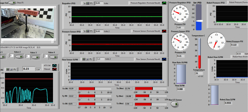
The LabVIEW Interface For Arduino Toolkit can be used to create Arduino sketches in the LabVIEW environment.
Advanced Control with Simulink
Simulink from Mathworks is also a graphical programming language in which code is created by manipulating functional blocks in the development environment. One of the advantages of environments like LabVIEW and Simulink is that a designer can make use of provided robust algorithms, without having to make their controllers from scratch. The following block diagram was made in Simulink and used to implement closed-loop control of a PneuNets Bending Actuator.
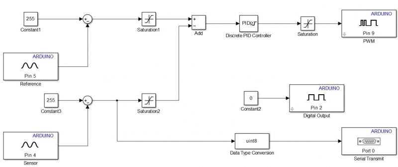
The Arduino Support package for MATLAB allows you to develop software/algorithms using Simulink’s graphical programming language and download this algorithm to an Arduino device. The package has a built-in compiler that converts the block diagram into code that can be embedded and run remotely on the Arduino. This page contains details on how to set up and use the support package.
Using Simulink with Arduino
This page describes the steps required to set up Simulink to work with Arduino. The instructions assume that you have MATLAB installed on your computer.
To use Simulink to create code that can be run on the Arduino, we need to install the Arduino Support Package from Simulink. We can install the support package from directly within the MATLAB environment. To do this, do the following:
- Open up MATLAB.
- Navigate to Resources/Add-Ons and click the drop-down arrow.
- Click “Get Hardware Support Packages”
- When the Support Package Installer box opens up, select “Install from Internet”.
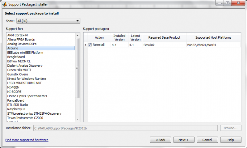
- A box that looks like the following will open up. Select ‘Arduino’ in the box on the left, and check ‘Install’ for the entry that has ‘Simulink’ under the Required Base Product (this should be the only entry).
- Follow through with the installation
Using the Arduino Support Package
- In the MATLAB command prompt, type in simulink and hit ‘enter’.
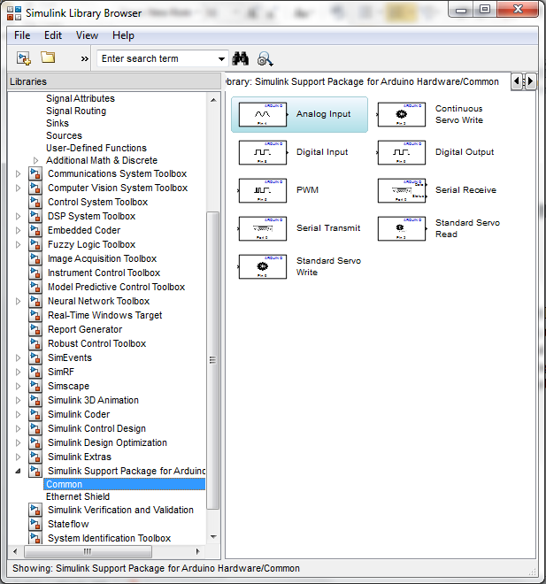
- When the library browser opens up, scroll down and you should see a new library entitled ‘Simulink Support Package for Arduino.’
- You can drag-and-drop these blocks into your model as you would normal Simulink blocks. You can also use blocks from other libraries.
