EGaIn Sensors
These sensors use liquid metal (eutectic Indium Gallium alloy, a.k.a. EGaIn) inside flexible microchannels. When stretched, the geometry of the channels changes resulting in a change of resistance. By measuring the change in resistance it is possible to calculate the strain (or amount of stretching).
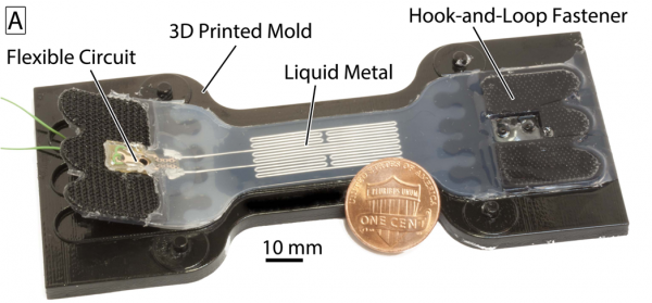
This documentation set contains files and instructions to support the design, fabrication, modeling, and testing of a specific EGaIn Sensor. The main functional component of the sensor is a thin structure made of soft, hyperelastic silicone elastomer containing the microchannels. The thin elastomer is connected to a stiffer elastomer and hook-and-loop fasteners for easy attachment to external devices and components.
The main mode of measurement for these sensors is axial strain. When the sensor is stretched, the elastomer deforms, lengthening in the direction of stretch and contracting transversely. This in turn deforms the channels, changing the shape of the liquid metal “wire” which creates a measurable increase in resistance.

| Some of the information contained in this web site includes intellectual property covered by both issued and pending patent applications. It is intended solely for research, educational and scholarly purposes by not-for-profit research organizations. If you have interest in specific technologies for commercial applications, please contact us here. |
Design
Motivation for Soft Sensors
|
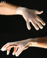
For wearable applications, sensors are needed that are comfortable, conform to the body, and do not alter or restrict the natural movement of the wearer. In addition, the sensors must be able to function at the high strains caused by the natural movement of the body, especially at the joints. Soft sensors are able to meet all of these requirements, as they are highly compliant, lightweight, stretchable, and impact-resistant. Beyond wearable applications, sensors capable of interfacing with soft actuators are necessary for the further development of soft robotics as a field, to enable more robust control of soft robotic devices. |
A glove embedded with soft sensors |
Sensor Components
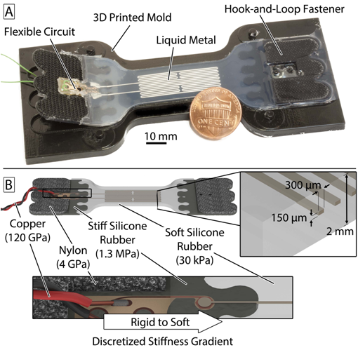
The main functional component of the sensor is a thin structure made of soft, hyperelastic silicone elastomer containing microchannels which are filled with liquid metal alloy. When the sensor is stretched, the elastomer deforms and the geometry of these microchannels is altered. This results in a change in the resistance of the circuit which can be measured. For a more detailed explanation of the sensing principle, read the Modeling section.
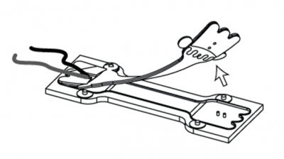
A hook-and-loop fastener (Velcro) is used to attach the sensor to structures that are going to be measured. A section of stiffer elastomer acts as an intermediate between the soft silicone rubber that makes up most of the sensor and the much stiffer fastener material. Two copper wires are inserted into the liquid metal for measuring the properties of the liquid metal “wire”. The version shown in the image below has a flexible circuit for this purpose, but that component is not included in the version described here as it required equipment not available to the average user.
Discretized Stiffness Gradient
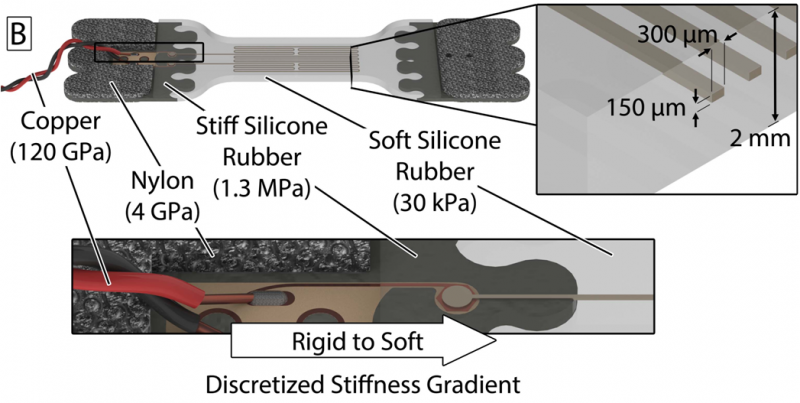
One of the challenges with devices that utilize soft materials is interfacing between the soft materials and hard materials within the device. The connection point between two materials with a large difference in stiffness usually becomes the point of failure of the device, through delamination.
Inspiration can be taken from nature, where these hard/soft interfaces are common. One example is the beak of a squid, which is very hard with a modulus of as high as 9 GPa, but is embedded in and actuated by soft muscular tissue. Analysis of the beak reveals that there is a large stiffness gradient from the beak tip to the base, spanning 2 orders of magnitude (Miserez et al. 2008).
The device design applies this as a “discretized stiffness gradient” in which 4 different materials are arranged in order of stiffness to gradually span the 7 orders of magnitude of difference in stiffness between the 120 GPa copper wire and the 30 kPa soft silicone rubber. By “distributing” this stiffness difference over multiple interfaces, instead of having one interface with a drastic jump in stiffness, the sensors are more robust in design and can withstand higher forces.
Variation: Morphology
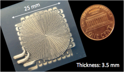
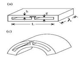
By changing channel geometry, other sensing modes besides strain are possible, including pressure, shear, and curvature (Vogt et al. 2013).
|
 |
|
 |
|
 |
By stacking several different channel shapes, a single device capable of multiple types of sensing is possible (Vogt et al. 2013).
|
|
 |
|
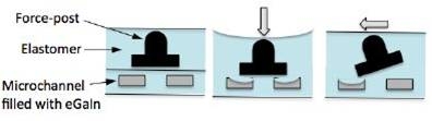
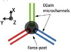
Three U-shaped microchannels at 120o intervals to detect forces in three directions. |
Three microchannels with increased spatial resolution |
Variation: Material
Other conductive materials can be used to fill the channels. One option that is more biocompatible than EGaIn is ionic liquid, though gradual evaporation of water from the device poses a problem as it affects the ion concentration and conductivity of the liquid.
The Lewis group at Harvard has created a method to directly 3D print conductive circuits into a soft elastomer matrix, using a novel carbon grease-based ink. This enables much more rapid fabrication of complex circuits (Muth et al. 2014).
|
|
 |

Fabrication
This section breaks down the necessary steps to mold and assemble the EGaIn sensor described previously. The sensor consists of two halves that are molded separately and then bonded together. The molding and bonding processes are assisted by an oven and spin-coater to speed up the curing and bonding procedures. EGaIn is then injected into the channels inside the sensor and electrical wires are attached. An overview of this process is given below.
Overview of steps to be taken
|
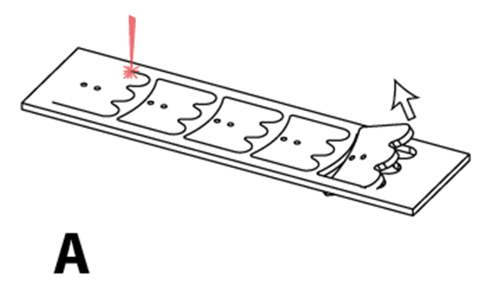
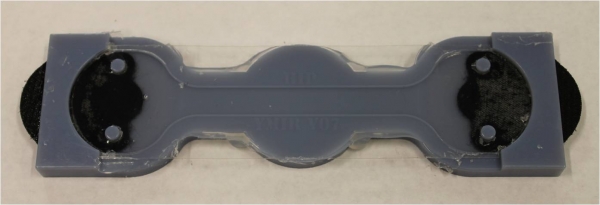
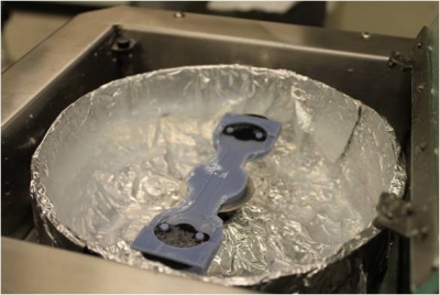
(A) Velcro is laser cut into desired shape.
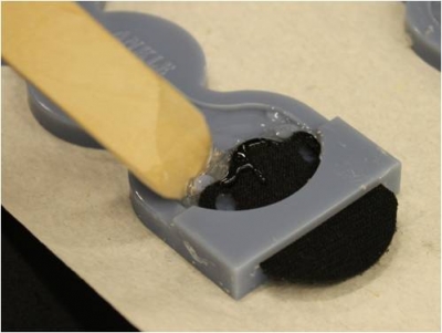
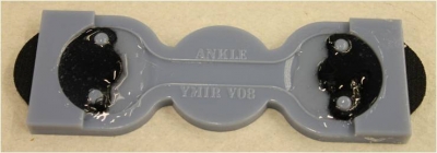
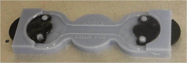
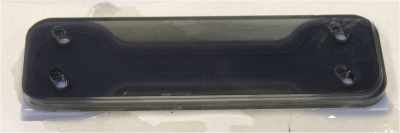
(B) Velcro is placed in the bottom-half mold and encapsulated in stiff silicone rubber.
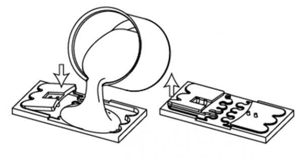
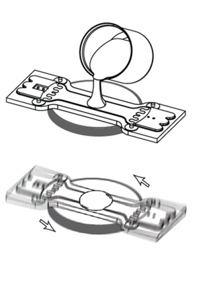
(C) The encapsulated velcro in the bottom-half mold and the top-half mold are cast with soft silicone rubber.
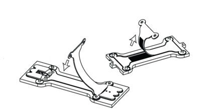
(D) After curing the bottom-half mold, a small amount of soft silicone rubber is spun on to it to act as an adhesive layer for lamination.
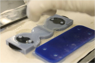
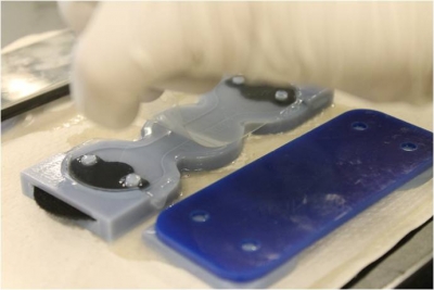
(E) The top-half sensor is demolded and laminated to the bottom-half.
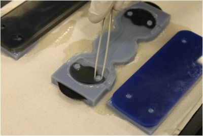
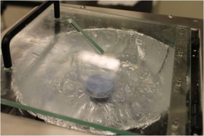
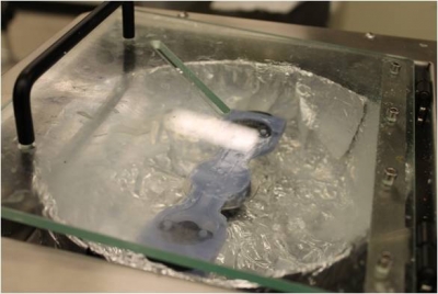
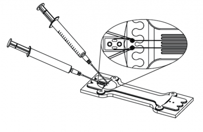
(F) Liquid metal alloy is injected into the microchannels with one needle while a second is used to evacuate the entrapped air.
(G) To complete the sensor, wires are inserted into the soft elastomer and encapsulated with rigid epoxy for strain-relief.
|
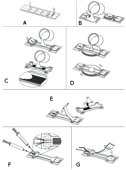 |
Diagram of full sensor
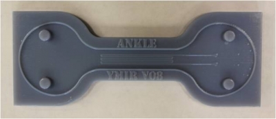
Overview of Mold
|
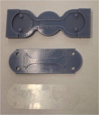
Top mold (mold, acryllic plate and transparency shown) |
|
| Top mold: This half of the mold has the negative impression of channels that will contain EGaIn. Transparency and acryllic plate used to close the mold are shown in the bottom picture. | |
|
Bottom mold:
When molding the soft elastomer, use the transparency and the flat side of the top plate.
When molding the stiff elastomer, use the raised side of the acrylic plate.
|
Bottom mold (mold, top plate and transparency shown) |
Bill of Materials
This section will give a list of items that are used in this project with selected links to suppliers. You can download a more detailed Bill of Materials sheet here.
Note: Many of the items listed are just examples and you can use your own discretion to substitute parts which are easier or cheaper to obtain.
Mold Components
 |
|
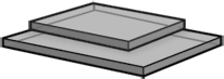
| Top Mold | Acryllic plate and Transparency film |
 |
|
| Bottom mold (mold, top plate and transparency shown) |
Click here to download the .STL files needed to 3D print the molds for this sensor.
Click here to download the .DXF files needed to laser cut the transparencies and plates.
If you would like to modify the molds click here to download the SolidWorks part files.
Polymer Materials
 |
 |
 |
|
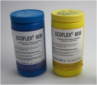
Soft silicone rubber (EcoFlex 0030, Shore OO-30 hardness, E = 30 kPa) |
Stiff silicone rubber (SORTA Clear 40, Shore A-40 hardness, E = 1.3 MPa) |
Mold Release (Ease Release 200 works well) |
Other Materials
 |
 |
 |
|
Velcro material, Loop 3008 type* |
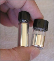
Eutectic indium gallium alloy (EGaIn). Need ~100 uL per sensor though it depends on channel geometry. |
Silpoxy silicone adhesive |
|
|
|
|
|
Transparency film |
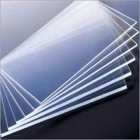
Acrylic (1/4" thick) |
*Type selected because it is very thin (low profile)
Tools & Hardware
 |
 |
 |
|
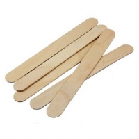
Tongue Depressors |
Tweezers | Weights |
 |
 |
 |
|
2 small syringes (1.5-3 mL) |
2 needles (27 gauge) |
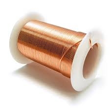
Electrical wire** |
 |
||
|
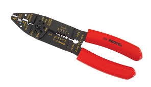
Wire Strippers
|
**Smaller diameter is better. Here we use 36 AWG copper wire.
Equipment
 |
 |
 |
|
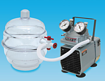
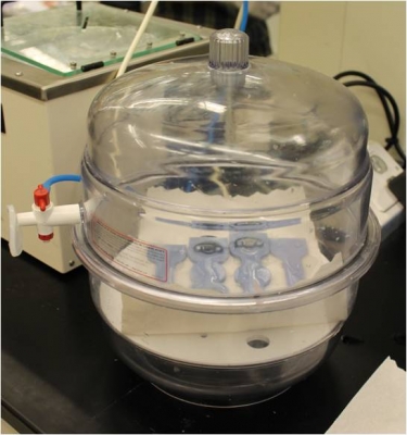
Vacuum chamber |
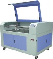
Laser cutter |
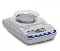
Mass scale |
 |
 |
 |
|
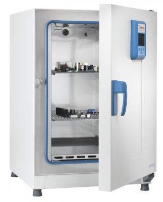
Lab oven |
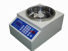
Centrifugal mixer |
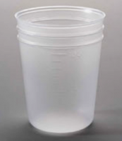
Mixing cups |
 |
 |
 |
|
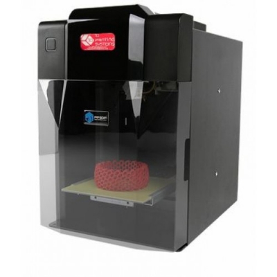
3D Printer*** |
Spin-coater |
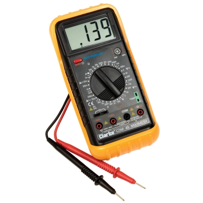
Multimeter |
 |
||
|
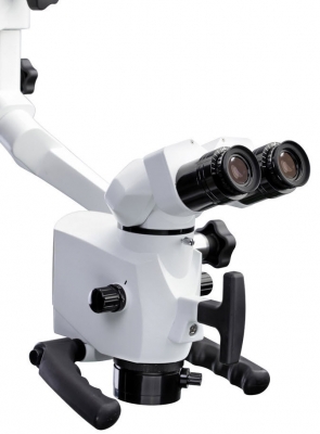
Microscope (optional) |
***Minimum need 10x better than dimensions of your structure. i.e. object spatial res. On micron level, but smallest features are 100 microns. Same for FDM. Aim for few hundred microns wide/tall
| SRT_EGaIn3DPrinterFiles.zip | 1.24 MB | |
| SRT_EGaInLaserCutterfiles.zip | 9 KB | |
| SRT_EGaInMoldModel.zip | 2.1 MB | |
| EGaIn Detailed BOM.xlsx | 13 KB |
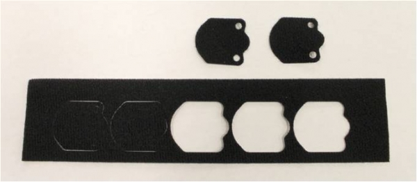
Step 1: Prepare Velcro Fasteners
|
The first step involves laser cutting the shown pattern from Velcro sheets. Laser cut the Velcro with the fuzzy loop side facing upwards, not the hook side. The .DXF files used to create this pattern can be found here.
Note: Make sure to cut 2 pieces for each sensor you want to make.
|
 |
|
 |
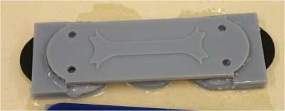
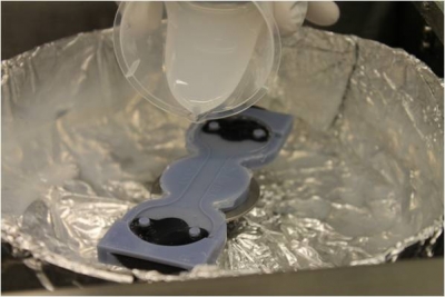
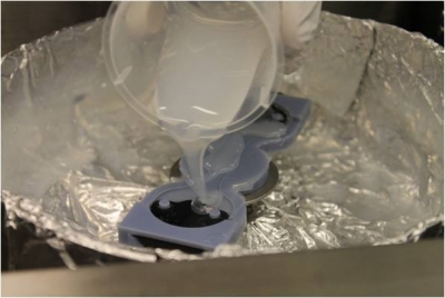
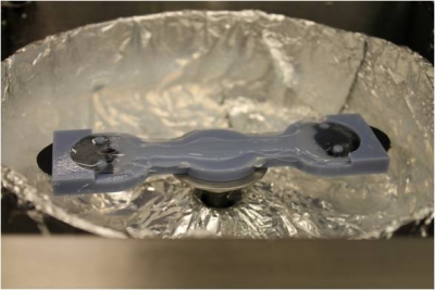
Step 2: Mold Stiff Ends
|
 |
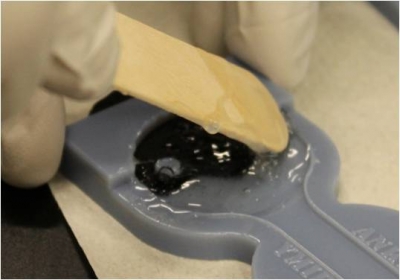
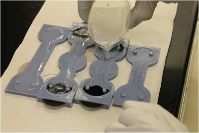
Pour stiff rubber
 |
|
 |
|
 |
|
 |
|
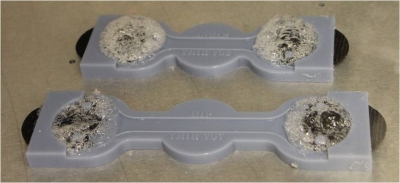
Degas elastomer
 |
|
 |
|
Seal and press mold
 |
|
 |
|
Check for defects
 |
|
 |
|
Step 3: Mold Top and Bottom Layers
|
 |
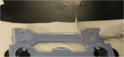
Pour EcoFlex and Degas
 |
|
 |
|
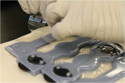
Add Transparency
|
|
 |
 |
 |
 |
 |
Note: There is a transparency for both the top and bottom mold and they both need to be placed down at this time.
|
Cover Mold
 |
 |
|
|
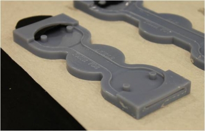
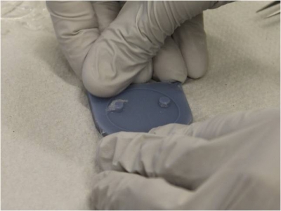
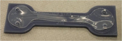
Demolding
 |
|
 |
|
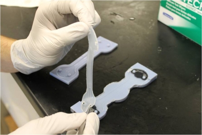
Step 4: Bond Top and Bottom Layers
|
 |
Add Adhesive Layer
 |
|
 |
|
 |
|
 |
|
Set New Layer in Oven
 |
|
 |
 |
Align Layers
 |
|
 |
 |
 |
|
 |
|
 |
|
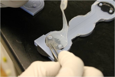
Step 5: Inject EGaIn
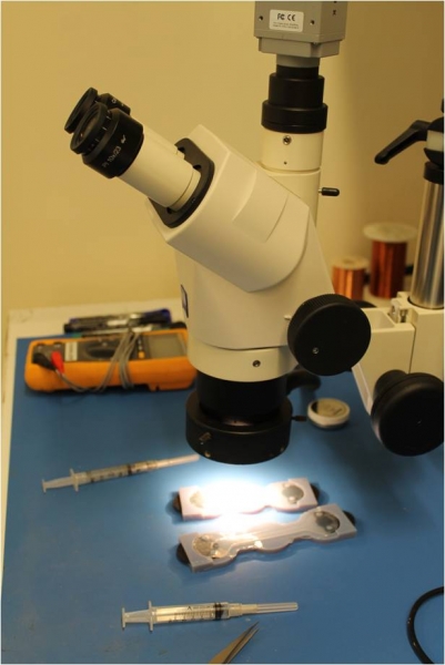
Setup
|
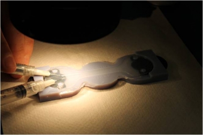
The next step involves injecting the EGaIn into the hollow channels of the sensor. In order to do this, you will need 2 syringes with 27-gauge needles.
|
 |
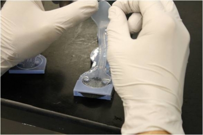
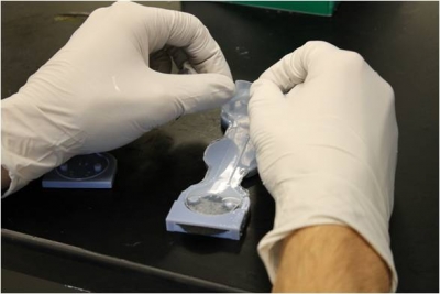
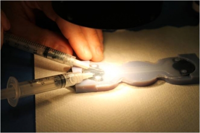
Injecting
 |
|
 |
 |
|
|
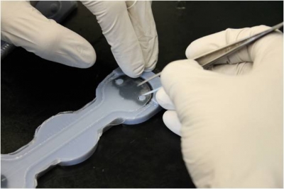
Step 6: Plunge Wires
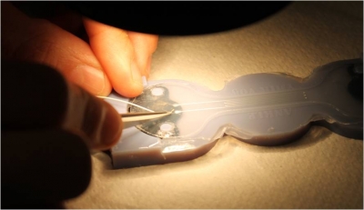
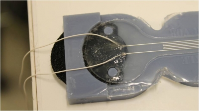
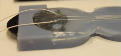
Prepare and Insert Wires
 |
|
Test and Seal
 |
|
 |
|
Step 7: Demold
|
 |
Modeling
Analytical
| The sensors consist of liquid metal channels embedded in elastomer. When the sensor is stretched, the elastomer deforms, lengthening in the direction of stretch and contracting transversely. This in turn deforms the channels, changing the shape of the liquid metal “wire” which creates a measurable increase in resistance. | 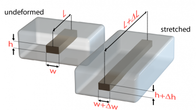 |
The change in resistance can be modeled by the following formula:
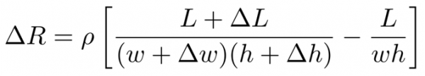
where R is resistance, ρ is resistivity (of the liquid metal), and L, w and h are the length, width and height of the channels. This formula can be further simplified using the fact that the Poisson’s ratio for incompressible materials is ν = 0.5. By defining the geometry changes in terms of strain and this ratio (ϵ = ∆L/L, ∆w = −νϵw, ∆h = −νϵh), the equation simplifies to:
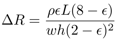
Since ρ is known (29.4 × 10⁻⁸ Ω⋅m for eGaIn) and L, w and h can be measured from the unstretched dimensions of the sensor channels, this equation gives the theoretical relationship between sensor strain and resistance change.
Testing
Connecting the sensor
The sensors can be treated as variable resistors when creating a circuit for the purpose of testing. The resistance across the 2 wires coming out of the sensor will increase as the sensor is stretched (expect ~2.5 Ω when unstretched and up to 15 Ω when stretched by 200%).
By applying a precise, controlled DC current through the sensor, we can measure the voltage drop across the sensor (this reading should be amplified with an operational amplifier) and use that to accurately calculate the resistance across the sensor.
A simple way to log the sensor data is to hook up the sensor to a microcontroller with an analog-to-digital converter, such as an Arduino, and transmit the data to your computer. However, if you do this, make sure your circuit operates within the safe input voltage range of your microcontroller! If you are unfamiliar with microcontrollers, you can refer to this section from the Control Board pages for some basic instructions for working with an Arduino.
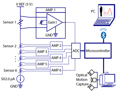
An example setup for a soft sensing suit using EGaIn sensors (Mengüç et al. forthcoming 2014)
Cyclical Testing
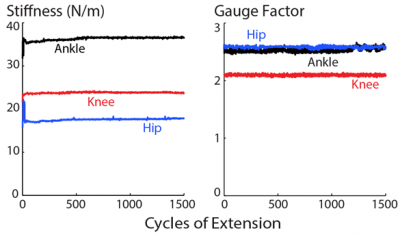
Another important requirement for sensors is reliability: they should behave consistently throughout their lifetime. Mechanical fatigue of the materials in the sensor can alter its behavior over time. To test this, the sensors described in this documentation were mounted in a tensile testing machine and cyclically loaded for 1500 cycles to nearly twice the maximum extension expected for the intended application (joint angle measurement), around 200% strain, and at the maximum extension rate possible on the testing machine (25 mm/s). Each sensor's mechanical (stiffness) and electrical (gauge factor) behaviors were monitored throughout.
As seen in the below graph, the sensors were consistent over the 1500 cycles, both mechanically and electrically. Fitting lines to the data and taking the slope shows that stiffness increased 0.34-2.5% for the different sensors, while gauge factor changed by around 0.05-2% (Mengüç et al. forthcoming 2014).
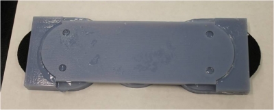
Compression Testing
A drawback of these sensors is that they are cross-sensitive to transversal compression (i.e. if pressure is applied perpendicularly to the flat face of the sensor, as opposed to stretching the sensor longitudinally). Since this also introduces deformation of the liquid metal channels, it also affects the resistance, and this resistance change can be misinterpreted as a change in extension and introduce error into the sensor readings.
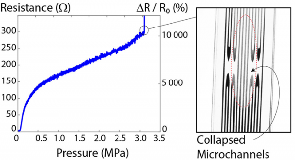
To better understand this behavior, a flat plastic punch with 10 mm diameter was used to compress the center of the sensor in a materials testing machine. A very slow rate of compression was used (0.0167 mm/s) to reduce rate-dependent viscoelastic effects. Plotting the applied pressure (load over the punch area) against the measured changes in resistance shows a nonlinear relationship (Mengüç et al. forthcoming 2014).
Above a certain compressive load (~3 MPa pressure), the microchannels will be squeezed shut, breaking the conductive liquid metal path, and resistance goes to infinity. However, this is temporary - gently massaging the collapsed area will reopen the channels and restore sensor function.
In all applications of these sensors care should be taken to mount them in such a way as to reduce the risk of compression contaminating strain readings. For example, in the case of wearable sensors for joint angle measurement, sensors are placed away from bony landmarks of the body, where impacts or falls could cause the sensor to be compressed against the landmark.
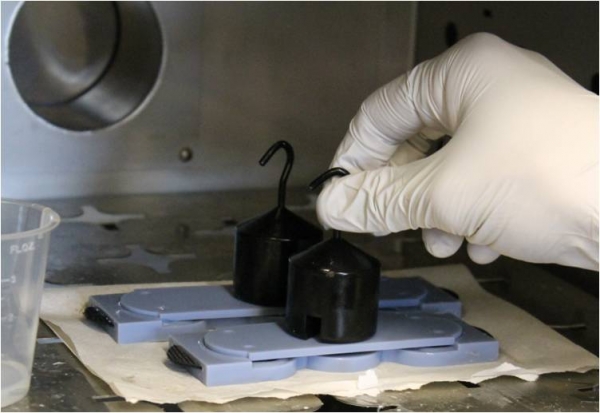
Failure Testing
|
Failure testing is used to determine the durability of sensors, and when and how they break. This information is useful for making sure that there is a sufficient factor of safety for your sensor application. To test the sensors described in this documentation, the sensors were placed under increasing load/strain until failure. There was a wide variation of failure strains even among sensors of identical shape and dimension. For example the 3 ankle sensors tested failed at strains of 247%, 339%, and 396%. This is due to manufacturing variability as these sensors are currently made by hand instead of an automated process (Mengüç et al. forthcoming 2014). |
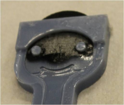
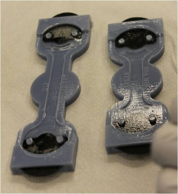
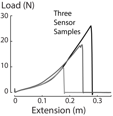 |
| While the sensors took different amounts of load to fail, all of the sensors failed in the same way: fracture at the interface between the stiff silicone rubber and the hook-and-loop fastener. According to the discretized stiffness gradient mentioned in the Design section, this particular interface spans 3 orders of magnitude from 1.3 MPa to 4 GPa, while the other interfaces only span 2 orders. Adding more steps to the discretized gradient to reduce these stiffness gaps may increase the amount of load that these sensors can withstand (Mengüç et al. forthcoming 2014). | 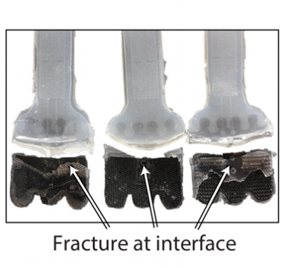 |
Downloads
Files for Fabrication
- Mold 3D Printer Files (.zip)
- Mold Laser Cutter Files (.zip)
- Mold Model .SLDPRT Files (.zip)
- Detailed Bill of Materials (.xlsx)
| Some of the information contained in this web site includes intellectual property covered by both issued and pending patent applications. It is intended solely for research, educational and scholarly purposes by not-for-profit research organizations. If you have interest in specific technologies for commercial applications, please contact us here. |