Fluidic Control Board
The Soft Robotics Toolkit Control Board is an open source hardware platform that can be used to operate and control fluidic soft actuators, such as the PneuNets Bending Actuator or the Fiber-Reinforced Actuators described on this site. The purpose of the control board is to act as a prototyping and testing tool, and to provide students with a hands-on understanding of how to control fluid-operated soft robots. It also enables designers to quickly test the behavior of pneumatic soft actuators.
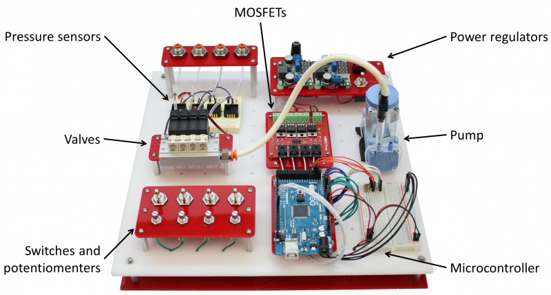
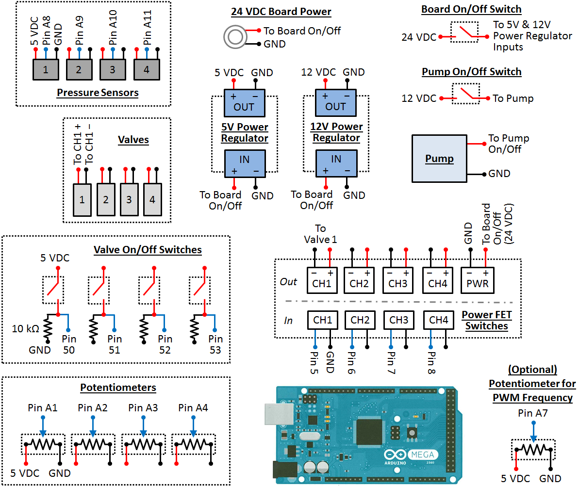
| The board consists of a pump (which provides pressurized fluid to the system) and a set of solenoid valves (which can open and close to direct the flow of fluid in the system). The pressure in the system is regulated by Pulse-Width Modulation (PWM), which involves the controlled timing of the opening and closing of the valves. Pressure sensors provide feedback on the behavior of the system. The board can be controlled manually (by adjusting switches and knobs) or automated via software running on the included Arduino microcontroller. |
|
This section of the website contains the files and instructions required to build your own control board for use with your own fluid-operated soft robots. To build the board all that is needed is some basic electronics skills (such as soldering two wires together). The bill of materials section provides the list of required components. Operating the board is relatively straightforward. We provide some example code that can be used to control the system, and provide guidelines on how to modify this code to suit your projects.
| Control Board PWM Code.txt | 2 KB |
Design
The control board is intended to be as modular and reconfigurable as possible, so that users can modify it to suit their particular design needs. This documentation will cover the fabrication and operation of a control board for pneumatic (air-operated) systems. The same guidelines will apply for a hydraulic (water-operated) control board, however it will need to use different components (discussed below).
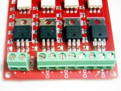
The board consists of:
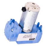
- A miniature diaphragm pump as the air source, which can provide up to 30 psi of pressure.
- Solenoid valves which can direct the flow of air in the system.
- Pressure sensors which can provide feedback on the behavior of the system.
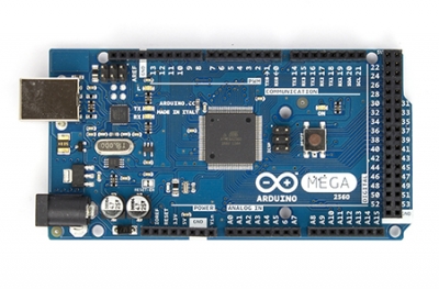
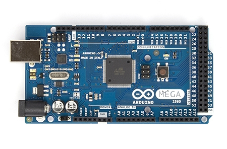
- A microcontroller (Arduino Mega), which enables users to interface with the hardware using their own computer via a USB cable (serial port) connection. Users can control various components or get sensor readings in this way, and write programs that use these elements for more advanced control of soft actuators.
- Switches and MOSFETs that can control the opening and closing of the solenoid valves.
- Rotary potentiometers ("pot") that control the pressure in the system (each controls the pressure in one channel).
- A breadboard to allow components to be added to the system.
- Power jacks.
- Various connectors, fixtures, and tubing.
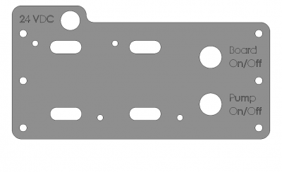
The base structure of the control board is a sheet of acrylic with a laser-cut "pegboard" design (the white board in the above image), which makes it easy to reconfigure, add, or remove board components. Most of the components are mounted to laser-cut acrylic parts (the red pieces in the above image) which help to organize the board and also make reconfiguring the system easier.
On the next page, we discuss some options and alternatives for modifying the board to best suit your needs.
Variations
Variation: Operating Fluid
The choice of operating fluid largely depends on your application. Water and air each have their own advantages and disadvantages as an operating fluid. For example, a pneumatic system can draw air from the environment (so the system doesn't need a reservoir) and any leaks that occur will not cause a mess. However, air is a compressible fluid and this can mean that it takes more energy for the pump to compress the air to reach the desired pressure. Furthermore, for some medical applications, particularly when an actuator will interact with blood, using air presents serious safety concerns.
The opposite is true for hydraulic systems: they require a reservoir and leaks will result in water spillage which may cause problems, but the system may be more energy efficient and water may be a safer choice for some applications.
As mentioned on the previous page, we describe a pneumatic control board here but it is relatively straightforward to use these instructions to build a hydraulic board. The main difference to consider is the selection of components. The following items on the Bill of Materials should be changed if you want to build a hydraulic control board (in most cases the vendors offer hydraulic versions of these parts):
- Pump
- Valves
- Pressure sensors
- In addition, a water reservoir will need to be added.
All other parts of the control board should stay the same, and the general fabrication and operation instructions provided here should apply.
Variation: Alternative Components
Most of the components on the board (and the particular models and brands of each component) can be replaced with alternatives based on cost, availability, and performance. We have found parts and suppliers specified here to be easy to obtain in the United States, but there may be better local options in other parts of the world. The part specification we provide can be useful in finding alternative components. We strongly advise you to get in touch with vendors directly to discuss your particular needs; most vendors can provide design expertise in their area and this can save you a lot of time and money.
Here we discuss some particular alternatives, but this list is by no means exhaustive:
- The MOSFETs can be replaced with motor drivers such as these.
- There is a massive variety of solenoid valves available. Some of these are designed for use with specific manifolds so before you buy any be sure to check if they are only compatible with certain setups. On that note, the use of a manifold can help to keep the board compact and well-organized, by eliminating the need for multiple branchhes of tubing.
- When selecting a pump, the important parameters to consider are power consumption, weight and volume, operating pressure, and flow rate. These will depend on the types of applications you are interested in. For example, we have chosen a pump that is small and light and has relatively low power consumption (compared to less expensive pumps). We chose this pump so that the board could be modified for portable applications. If, however, you plan to always use the board as a static bench-based platform then the weight, size, and power consumption will be less of an issue and you can probably find a cheaper pump that will suit your needs. For the fluidic actuators described on this site we have found that an operating pressure of 30 psi and flow rate of about 1 SLPM is sufficient. Again, these values depend on your applications.
Variation: Pressure Regulation
As mentioned above, the current design uses MOSFETs to control the switching of the solenoid valves. This setup makes it possible to use pulse width modulation (PWM) to control the pressure of the fluid passing through these valves. During PWM, high-frequency pulses are sent to the solenoid valves, opening and closing them rapidly. By varying the length of these pulses, the amount of time the valve is open or closed is adjusted, and therefore the output pressure is adjusted.
The drawback of using PWM on the control board is that it is less straightforward to set up. For beginners with relatively little electronics and programming experience, this is not the easiest method to start with. The other option for pressure control is to use a pressure regulator. While being easier to use, pressure regulators can be expensive and allow for less control of the system. Using a single regulator allows you to vary the pressure of the whole system, but if you want different pressure in different parts of the system (e.g. different pressures for different actuators) then you need a way to control the pressure at each valve. PWM has the advantage that each valve is individually addressable, which solves this problem. However if that isn't a problem for your system, then a pressure regulator might make sense.
Variation: Sensors
Sensors can easily be added to or removed from the board without affecting its performance. The choice of sensors again depends on what types of applications you are interested in.
- A flow sensor can probably be added to monitor flow conditions.
- The breadboard allows easy interfacing of additional sensors. For example, a previous project team added a gyroscope to track the motion of their fiber-reinforced actuator. Other users have embedded flex sensors in their actuators to track bend angle.
- On the other hand, if you wish you could build a control board with no sensors at all.
Assembly
|
This section lists the parts needed to build your own pneumatic control board, and gives an overview of the assembly steps involved. See the previous section for a discussion of alternative components you might want to use, for example if you need to use water instead of air as your operating fluid. The overall assembly process will remain the same. Drawing files (.dxf) of the laser cut acrylic parts can be downloaded by clicking here, and the Arduino code we will use can be downloaded by clicking here. |
 |
Building the board involves some basic soldering. If you have never soldered before there are many useful introductory tutorials online. The video below (taken from this tutorial from SparkFun) gives a good introduction to the basic techniques and equipment for soldering.
| Control Board DXF Files.zip | 83 KB | |
| Control Board PWM Code.txt | 2 KB |
Bill of Materials
This section will give a list of items that are used in this project with selected links to suppliers. You can download a more detailed Bill of Materials sheet here.
Note: Many of the items listed are just examples and you can use your own discretion to substitute parts which are easier or cheaper to obtain.
Major Components
|
|
|
|
Miniature Diaphragm Pneumatic Pump |
Pressure Sensor (x4)
|
|
|
|
|
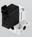
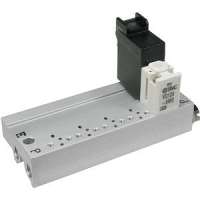
Solenoid Valve (x4) |
Manifold |
|
|
|
Power MOSFETs: 4 Opto-Isolated Power FET Switches
|
Arduino MEGA
|
|
|
|
|
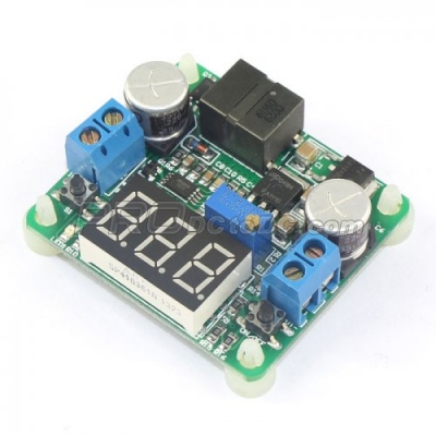
Power Regulator (x2) |
Toggle Switch (x6) |

For part and vendor information not show on this page refer to the Control Board Bill of Materials excel file. This excel can be downloaded here.
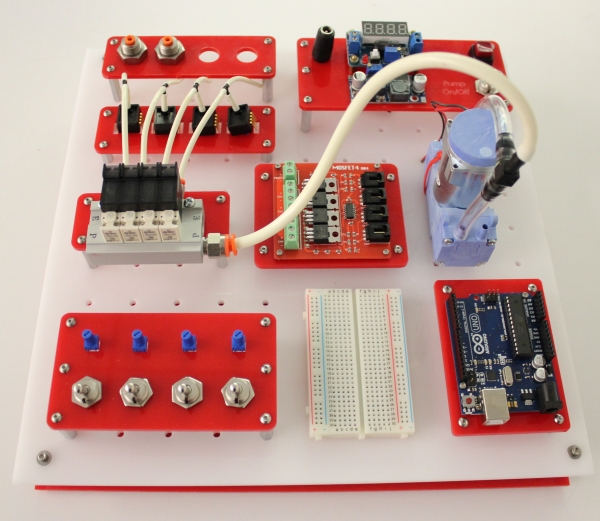
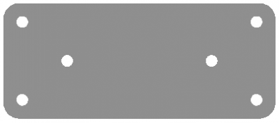
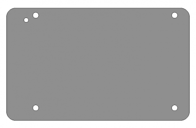
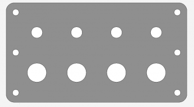
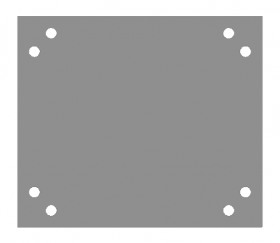
Base
These parts simply hold the above components in place. Use a laser cutter (make sure you are trained first!) to cut these pieces out of acrylic sheets. We use 3mm acrylic for all parts except the base board (6mm acrylic). Cut 2 copies of the base board. Download the .dxf files for cutting here.
|
|
| Output ports | Manifold |
|
|
| Arduino MEGA | Switches |
|
|
| MOSFETs |
Base board (12"x12" / 300mmx300mm) |
|
|
| Power |
| Control Board DXF Files.zip | 83 KB | |
| control_board_v2_bom_8-16edit.xlsx | 33 KB |
Assembling the Board
Mounting
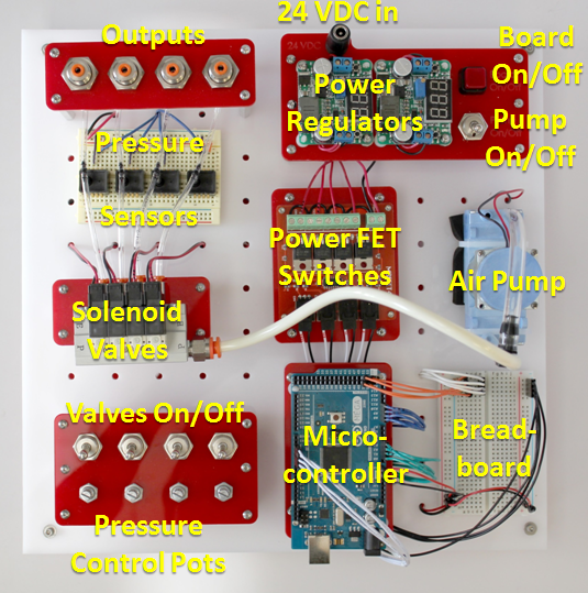
At each corner of the baseboard, install a standoff using a single screw with a plain washer. This elevates the board to make room for the wires and connections underneath.
Solder any necessary wires to all the electronic components (follow the data sheets and the below wiring diagram). Using heat shrink tubing may also be a good idea to prevent shorts. Next, mount all the of the components onto the baseboard, following the image below. Use zip ties, screws, washers, nuts and spacers wherever needed. Connect the air flow between components using appropriate tubing.
Wiring
Now that all the components are in place, they need to be connected to each other, following the wiring diagram below. A good place to start is by connecting all the components to power. Use red and black wires to represent voltage supply and common (ground), respectively. It may be helpful to use a bus to manage the various power wires.
When connecting signal wires, be careful not to mix up the Arduino's digital and analog pins (analog pins are prefaced by 'A'). Use the breadboard as an intermediate between the components and the Arduino to help keep all the wires organized. You can also connect 5 VDC and ground to the Arduino's Vin and GND pins, respectively, so that it remains powered even if the board is not connected to your computer via USB.
Before connecting the control board to power, make sure there are no short-circuits. If the board doesn't work properly at first, use a multi-meter to diagnose the problem and double-check your wiring. After connecting all the power plugs, make sure none of the components are getting too hot!
Using the Control Board

Once you have built the board, you can start using it to control your soft fluidic actuators. This section contains some guidelines on using the board. For basic testing of your actuators (e.g. the type of motion they undergo when inflated, checking for leaks) it is probably sufficient to operate the board manually by using the switches and the potentiometer to vary the pressure and open and close the valves. You can also use the Arduino IDE to write some code that will automate the operation of the control board, for example if you want to test the fatigue strength of your actuator or you want to test out some predefined motion sequences. The Basic Control page discusses how to use the board in these ways.
For more advanced control, you can also use the Arduino IDE to write control software. Alternatively, you can use environments such as LabVIEW or Simulink to create the control or data acquisition software to run on the microcontroller. The Advanced Control page discusses some of these options.
Basic Control
Note: Always check the maximum air supply you provide to the system. Every component has its own specifications and can withstand different maximum pressures.
Basic Arduino control
Once the board has been wired following the assembly instructions, we need to program the Arduino Mega microcontroller. If you haven't done so already, set up your Arduino board using the official setup guide: Windows / Mac
If you were able to get the guide's Blink example to work, upload the sample code to control the board hardware. Those already familiar with Arduino programming can customize the code to fit their own needs.
Basic manual control
- Power the board by plugging in the 24 VDC power adapter.
- Press the "Board On/Off" button. The two power regulators should turn on and display outputs of 5 and 12 volts.
- Slowly turn one of the 4 potentiometer dials that control the valves. The solenoid valves should start actuating (they will make clicking noises) and a corresponding red light on top of the valve should blink. If nothing happens, try flipping the corresponding valve on/off switch. As you turn the dial, the actuation duty cycle (the ratio of the valve's on time to its off time) should vary.
- While a valve is actuating, slowly adjust the potentiometer on the breadboard (the one connected to Arduino pin A7). The frequency at which the valve actuates should change.
- Flip the "Pump On/Off" switch. The pump should turn on.
- While the pump is on, adjust the various potentiometer dials and feel the air coming out of the board outputs. The airflow should vary as you turn the dials.
- Plug in the USB cable to the Arduino board if it isn't already. Open the serial monitor. The pressure readings for each output (in PSI) should be displayed and continuously updating.
| Control Board PWM Code.txt | 2 KB |
Advanced Control
Advanced Control with the Arduino IDE
One of the advantages of using the Arduino microcontroller is the massive amount of support documentation and useful code libraries that are available. If there is a particular control architecture you wish to implement, there is a good chance that someone has published related Arduino code online. For example, see this guide to PID control using the Arduino, and this PID Arduino library.
Advanced Control with LabVIEW
LabVIEW is a development environment from National Instruments that uses a graphical programming language. Software code is created by dragging and dropping functional blocks and creating connections between these blocks. The following "virtual instrument", used in testing the performance of a PneuNets Bending Actuator, was created in LabVIEW.

The LabVIEW Interface For Arduino Toolkit can be used to create Arduino sketches in the LabVIEW environment.
Advanced Control with Simulink
Simulink from Mathworks is also a graphical programming language in which code is created by manipulating functional blocks in the development environment. One of the advantages of environments like LabVIEW and Simulink is that a designer can make use of provided robust algorithms, without having to make their controllers from scratch. The following block diagram was made in Simulink and used to implement closed-loop control of a PneuNets Bending Actuator.

The Arduino Support package for MATLAB allows you to develop software/algorithms using Simulink’s graphical programming language and download this algorithm to an Arduino device. The package has a built-in compiler that converts the block diagram into code that can be embedded and run remotely on the Arduino. This page contains details on how to set up and use the support package.
Using Simulink with Arduino
This page describes the steps required to set up Simulink to work with Arduino. The instructions assume that you have MATLAB installed on your computer.
To use Simulink to create code that can be run on the Arduino, we need to install the Arduino Support Package from Simulink. We can install the support package from directly within the MATLAB environment. To do this, do the following:
- Open up MATLAB.
- Navigate to Resources/Add-Ons and click the drop-down arrow.
- Click “Get Hardware Support Packages”
- When the Support Package Installer box opens up, select “Install from Internet”.
- A box that looks like the following will open up. Select ‘Arduino’ in the box on the left, and check ‘Install’ for the entry that has ‘Simulink’ under the Required Base Product (this should be the only entry).
- Follow through with the installation

Using the Arduino Support Package
- In the MATLAB command prompt, type in simulink and hit ‘enter’.
- When the library browser opens up, scroll down and you should see a new library entitled ‘Simulink Support Package for Arduino.’
- You can drag-and-drop these blocks into your model as you would normal Simulink blocks. You can also use blocks from other libraries.

Case Studies
The control board is designed to be reconfigurable to suit the requirements of your application. Depending on your application, you may need to modify the control board. This may simply involve simply rerouting tubing to change the airflow, or may require you to add new components. This page contains some examples of how others have modified the board for use in their projects.
Evaluation Platform
The platform shown below is used to test and characterize actuators. In addition to the Control Board components, it consists of a National Instruments data acquisition box, a 6-axis force and torque sensor, a high-definition camera with checkered background for calibration, and a LabVIEW interface running on a connected workstation. The camera is used in conjunction with image analysis software such as ImageJ to track actuator motion.

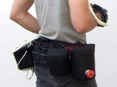
Control belt
The Soft Assist Glove (Polygerinos et al. 2013) is an ongoing project at the Biodesign Lab in Harvard. The aim is to create a wearable, pneumatically actuated glove which can assist users with hand disabilities. As the glove is intended to aid with activities of daily living, the auxiliary components for the glove need to be able to follow the user wherever they go. To achieve this, the control board components were mounted onto a wearable belt. The regulator and relays were replaced by motor drivers which allowed pulse width modulation (PWM) of the valves. The system was powered with a battery, which required the addition of components such as power regulators and fans. More details on the Soft Assist Glove can be found here.

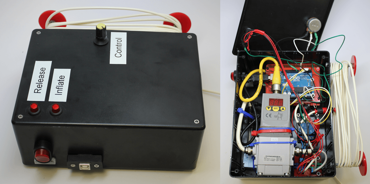
Portable control box
A design team working on an actuated glove for thumb rehabilitation (Maeder-York et al. 2014) designed a portable control box by placing the essential board components (pump, regulator, Arduino, valves, and relays) into a compact electronics enclosure with a simple interface that could be used by patients at home. More details on this project can be found here.